Tigercat 620 SKIDDER SERVICE MANUAL – PDF DOWNLOAD
Original price was: $89.95.$28.95Current price is: $28.95.
Tigercat 620 SKIDDER SERVICE MANUAL – PDF DOWNLOAD
Description
Tigercat 620 SKIDDER SERVICE MANUAL – PDF DOWNLOAD
DESCRIPTION:
Tigercat 620 SKIDDER SERVICE MANUAL – PDF DOWNLOAD
INTRODUCTION :
- An Operator’s manual, Service manual and a Parts catalog are provided by Tigercat to assist the dealer,
customer and operator in becoming familiar with the features of the 620 Skidder. - The operator’s manual will assist the operator with the techniques of proper and safe operation of the
Skidder. The service manual contains safety guidelines, a preventive maintenance schedule and
servicing procedures to ensure optimum machine performance. - Section 1 in both the operator’s manual and the service manual contains safety information that must be
followed. As well, throughout the rest of the manuals WARNING and CAUTION notices are displayed
where necessary, drawing attention to possible hazards when performing certain procedures. - Only trained personnel should be allowed to operate or work on the machine.
- The phrase “and up” appearing in this manual after the serial number implies that the related
information is current for any machine serial number HIGHER than the serial number preceding the “and
up”. - Tigercat reserves the right to make changes to the machine after this manual release date that may not
immediately appear in this manual. - Every effort is made to send out updates on a regular basis. If the machine in question was built after
the release date of this manual and there is a discrepancy, call Tigercat service department. The release
date appears on the first page.
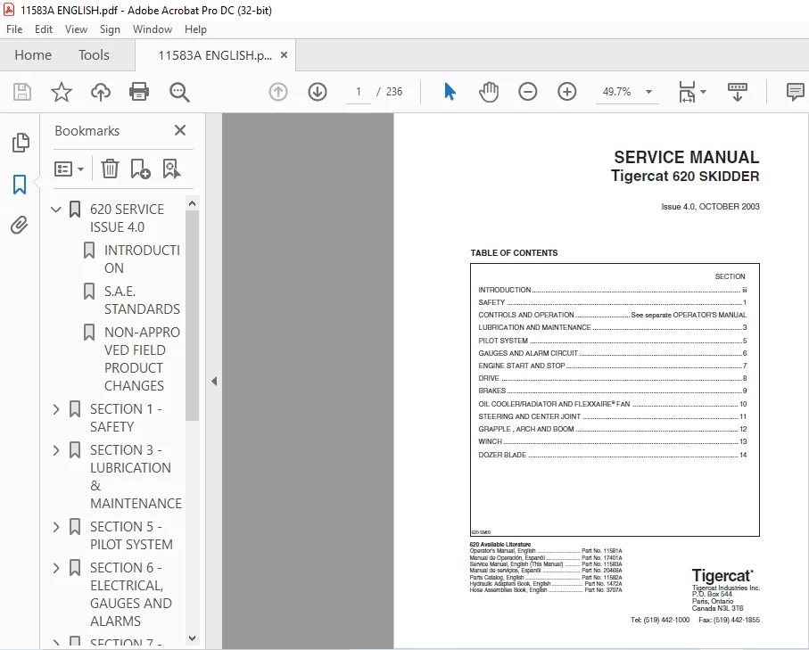
TABLE OF CONTENTS:
Tigercat 620 SKIDDER SERVICE MANUAL – PDF DOWNLOAD
620 SERVICE ISSUE 4.0…………………………………… 1
INTRODUCTION……………………………………….. 3
S.A.E. STANDARDS……………………………………. 4
NON-APPROVED FIELD PRODUCT CHANGES……………………. 5
SECTION 1 – SAFETY……………………………………… 7
ARTICULATION LOCK ………………………………….. 17
battery disconnect switch …………………………… 13
CAB SAFETY CABLE …………………………………… 16
CAB SUPPORT BRACE ………………………………….. 16
cooling system …………………………………….. 15
exhaust fumes ……………………………………… 18
FIRE PREVENTION…………………………………….. 7
FIRE PREVENTION GUIDELINES ………………………. 19
WHAT ELSE TO DO BEFORE YOU EXPERIENCE A FIRE ………. 20
WHAT TO DO AFTER A FIRE …………………………. 21
WHAT TO DO IN CASE OF A MACHINE FIRE ……………… 20
first aid …………………………………………. 10
Fluid leaks ……………………………………….. 15
Hydraulic Pressure hazard …………………………… 15
loose clothing hazard ………………………………. 16
PARKING THE MACHINE ………………………………… 13
protective clothing ………………………………… 9
SAFETY PRECAUTIONS, GENERAL …………………………. 9
SAFETY PRECAUTIONS, OPERATING ……………………….. 12
SAFETY PRECAUTIONS, SERVICING ……………………….. 15
SAFETY SYMBOLS …………………………………….. 8
Signal Words ………………………………………. 8
SECTION 3 – LUBRICATION & MAINTENANCE…………………….. 23
air cleaner maintenance …………………………….. 38
APPROVED HYDRAULIC OILS …………………………….. 29
center joint……………………………………….. 43
lubrication ……………………………………. 43
maintenance ……………………………………. 43
CHARGE PRESSURE FILTER ……………………………… 35
filter and lubrication schedule ……………………… 31
FILTERS……………………………………………. 32
AXLE RETURN FILTERS …………………………….. 37
CHARGE PRESSURE FILTER – DRIVE PUMP ……………… 35
FUEL FILTER/WATER SEPARATOR ……………………… 32
FUEL TANK STRAINER ……………………………… 33
HYDRAULIC OIL DOUBLE FILTERS …………………….. 34
HYDRAULIC TANK BREATHER FILTER …………………… 37
FIRE PREVENTION ……………………………………. 25
GENERAL MAINTENANCE ………………………………… 25
GRAPPLE SNUBBER MAINTENANCE …………………………. 40
HOUR METER ~ MAINTENANCE ……………………………. 24
LUBRICATION AND SERVICE POINTS ………………………. 31
NEW MACHINE MAINTENANCE …………………………….. 24
FIRST 50-100 HOUR INSPECTION AND SERVICE REPORT ……. 24
INITIAL PRE-DELIVERY INSPECTION ………………….. 24
OIL LOST FROM LEAKAGE ………………………………. 24
pressurized water system maintenance …………………. 44
SCHEDULED MAINTENANCE ………………………………. 26
FREQUENTLY …………………………………….. 26
8 HOURS ……………………………………….. 26
125 HOURS ……………………………………… 27
250 HOURS ……………………………………… 27
500 HOURS ……………………………………… 27
1000 HOURS …………………………………….. 28
SEASONAL ………………………………………. 28
SERVICE AND LUBRICATION POINTS ………………………. 31
SPEED CONTROL LEVER ADJUSTMENT ………………………. 54
STARTUP PROCEDURE AFTER MAJOR MAINTENANCE …………….. 52
TILTING THE CAB ……………………………………. 48
TORQUE CHART ………………………………………. 55
TORQUE CHART, GENERAL ………………………………. 56
WHEELS, INSTALLING …………………………………. 24
WINCH LUBRICATION – LANTEC ONLY ……………………… 51
WINCH LUBRICATION – LUFKIN ONLY ……………………… 50
SECTION 5 – PILOT SYSTEM………………………………… 57
CHARGE PRESSURE FILTER ……………………………… 59
CHARGE PUMP ……………………………………….. 58
CIRCUIT DESCRIPTION (6200111 to 6200150) ……………… 60
CIRCUIT DESCRIPTION (6200151 to 6200196) ……………… 62
CIRCUIT DESCRIPTION (6200197 to 6200232) ……………… 64
CIRCUIT DESCRIPTION (6200233 AND UP) …………………. 66
CIRCUIT DIAGRAM (6200111 TO 6200150) …………………. 61
CIRCUIT DIAGRAM (6200151 TO 6200196) …………………. 63
CIRCUIT DIAGRAM (6200197 TO 6200232) …………………. 65
CIRCUIT DIAGRAM (6200233 AND UP) …………………….. 67
PILOT MANIFOLD …………………………………….. 59
PRESSURE SETTINGS ………………………………….. 68
SECTION 6 – ELECTRICAL, GAUGES AND ALARMS…………………. 71
FUSE AND RELAY PANEL (6200111 TO 6200238) …………….. 80
FUSE AND RELAY PANEL (6200239 AND UP) ………………… 81
GAUGES AND ALARMS ………………………………….. 82
SCHEMATIC DIAGRAM (6200111 TO 6200180) ……………….. 72
SCHEMATIC DIAGRAM (6200181 TO 6200238) ……………….. 74
SCHEMATIC DIAGRAM (6200239 AND UP) …………………… 77
SENSOR DETAILS …………………………………….. 82
switch and sensor locations …………………………. 83
troubleshooting and testing …………………………. 82
wire colour code chart ……………………………… 80
SECTION 7 – ENGINE START AND STOP………………………… 85
DRIVE PREVENT VALVE ………………………………… 87
FUEL CONTROL VALVE …………………………………. 87
MAIN PUMP UNLOADING VALVE …………………………… 87
START CIRCUIT DESCRIPTION……………………………. 85
EARLIER DESIGN (6200111 TO 6200238) ………………. 86
LATER DESIGN – WITH LOW OIL PRESSURE SHUT-DOWN……… 85
(6200239 AND UP) ……………………………. 91
START CIRCUIT DIAGRAM……………………………….. 85
SERIAL NUMBERS 6200111 TO 6200180 ………………… 88
SERIAL NUMBERS 6200181 TO 6200238 ………………… 89
SERIAL NUMBERS 6200239 AND UP ……………………. 93
START MOTOR AND SOLENOID ……………………………. 87
START SOLENOID RELAY ……………………………….. 86
TACHOMETER SET-UP ………………………………….. 95
SECTION 8 – DRIVE………………………………………. 97
AXLES ……………………………………………..142
capacities ……………………………………..145
DIFFERENTIAL AND DIFFERENTIAL LOCKS ……………….143
DRAINING THE AXLES ………………………………144
filling the axles ……………………………….144
filling the axles, alternate method ……………….145
Lubrication …………………………………….144
OIL capacities ………………………………….145
OSCILLATION SHIM CHECK AND ADJUSTMENT (FRONT AXLE) ….147
Service brakes (front axle only)………………….. 97
BRAKE BLEEDING ………………………………144
BRAKE LINING INSPECTION ………………………144
SERVICING BRAKES …………………………….143
circuit description ………………………………… 99
DRIVE SYSTEM……………………………………….. 97
CHECK VALVE …………………………………….111
DRIVE CIRCUIT DIAGRAM……………………………. 97
REXROTH PUMP AND MOTORS (6200111 TO 6200150) ……112
REXROTH PUMP AND MOTORS (6200151 TO 6200230) ……113
SAUER PUMP AND REXROTH MOTORS …………………127
DRIVE FOOT CONTROL VALVE …………………………108
DRIVE MOTOR DESCRIPTION ………………………….106
DRIVE MOTOR SCREW ADJUSTMENTS …………………….121
DRIVE PREVENT VALVE ……………………………..109
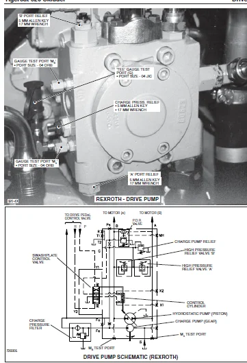
DRIVE PUMP DESCRIPTION – REXROTH ………………….100
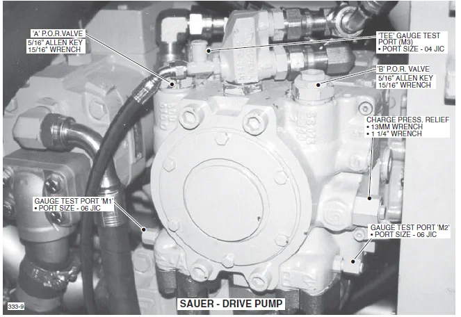
DRIVE PUMP DESCRIPTION – SAUER PUMP ……………….103
DRIVE PUMP PRESSURE SETTINGS ……………………..117
DRIVE SPEED CONTROL VALVE ………………………..110
hydraulic set-up – REXROTH PUMP / REXROTH MOTORS……. 97
Drive Motor pressure Adjustment ……………….119
drive Pump Pressure Adjustment ………………..116
Motor Begin of displacement control Pressure ……120
Motor Minimum displacement Adjustment ………….119
Motor pressure override adjustment (P.O.R.) …….123
hydraulic set-up – SAUER pump/ rexroth motors………. 97
Drive Motor pressure Adjustment ……………….134
drive Pump Pressure Adjustment ………………..131
Motor Begin of displacement control Pressure ……135
Motor Minimum displacement Adjustment ………….134
Motor pressure override adjustment (P.O.R.) …….138
HYDRAULIC OIL HEATING PROCEDURE ………………………111
TEST DRIVE – REXROTH PUMP AND REXROTH MOTORS…………… 98
Begin of Displacement Control Pressure …………….114
DIFFERENTIAL LOCKS ………………………………115
horsepower ……………………………………..115
Motor Pressure Override (POR) …………………….114
Steering Operation ………………………………115
TEST DRIVE – SAUER pump and rexroth motors…………….. 98
Begin of Displacement Control Pressure …………….128
DIFFERENTIAL LOCKS ………………………………129
GROUND SPEED ……………………………………130
horsepower ……………………………………..129
Motor Pressure Override (POR) …………………….128
Steering Operation ………………………………129
TRANSMISSION ……………………………………….141
TRANSMISSION IDENTIFICATION ………………………….130
WHEEL INSTALLATION ………………………………….146
TAPERED ASSEMBLY STUD ……………………………147
SECTION 9 – BRAKES………………………………………149
ACCUMULATOR…………………………………………149
accumulator …………………………………….150
CHARGING AND TESTING DEVICE ………………………151
CHARGING THE ACCUMULATOR …………………………151
CHECKING GAS PRESSURE ……………………………150
BRAKES……………………………………………..149
ACCUMULATOR and SERVICE BRAKES ……………………156
BRAKE PILOT VALVE ……………………………….150
Parking brake …………………………………..158
CHARGING VALVE, ACCUMULATOR ………………………….151
CIRCUIT DIAGRAM …………………………………….153
DIFFERENTIAL LOCKS…………………………………..149
ADJUSTING DIFFERENTIAL LOCK VALVES: ……………….156
CIRCUIT DESCRIPTION ……………………………..156
MAIN PUMP ………………………………………….152
Multifunction Valve………………………………….149
ADJUSTING HIGH PRESS RELIEF AND MAIN PUMP ………….154
DESCRIPTION …………………………………….154
HIGH PRESSURE RELIEF …………………………….154
Parking brake ………………………………………158
SECTION 10 – OIL COOLER/RADIATOR AND FLEXXAIRE® FAN…………159
CIRCUIT DESCRIPTION AND Operation …………………….162
CIRCUIT DIAGRAM …………………………………….163
FLEXXAIRE® FAN MAINTENANCE (OPTIONAL ITEM) …………….164
BLADE LOCK-OUT PROCEDURE …………………………168
CHECKING HUB OIL ………………………………..170
CIRCUIT DIAGRAM …………………………………167
FAN OVERVIEW ……………………………………166
HUB OIL CAPACITY (APPROXIMATE) ……………………170
LUBRICATION AND SERVICE INTERVALS …………………169
MAINTENANCE CHECKLIST ……………………………171
REMOVE DEBRIS USING CLEAN FUNCTION ………………..166
SAFETY …………………………………………164
OIL COOLER/RADIATOR DESCRIPTION ………………………160
RADIATOR/OIL COOLER DESCRIPTION ………………………160
SECTION 11 – STEERING AND CENTER JOINT…………………….173
CENTER JOINT………………………………………..180
checking center joint visually for looseness ……….180
checking the center joint preload …………………182
center joint preload adjustment ……………….183
DIAGRAM ………………………………………..182
grease seals – ORIENTATION ……………………….183
IDENTIFYING EARLIER AND LATER BEARINGS …………….181
lubrication …………………………………….180
maintenance …………………………………….180
IDENTIFYING EARLIER AND LATER BEARINGS ………………..181
PRIORITY VALVE ……………………………………..176
STEER CONTROL VALVE …………………………………174
STEERING……………………………………………173
CIRCUIT DIAGRAM …………………………………179
testing the Steering Operation ……………………….178
SECTION 12 – GRAPPLE, ARCH AND BOOM……………………….185
CIRCUIT DESCRIPTION………………………………….185
ARCH …………………………………………..191
ARCH/BOOM ………………………………………197
grapple open/close ………………………………205
GRAPPLE ROTATE – ESCO GRAPPLE …………………….205
GRAPPLE ROTATE – TIGERCAT GRAPPLE………………….185
WITH DANFOSS MOTOR …………………………..204
WITH WHITE HYDRAULICS MOTOR …………………..204
CIRCUIT DIAGRAMS…………………………………….185
ARCH/boom ………………………………………196
GRAPPLE ………………………………………..203
SINGLE ARCH …………………………………….190
GRAPPLE CONTROL VALVE………………………………..185
dual FUNCTION ARCH SECTION ……………………….194
grapple rotate and open/close SECTIONs …………….201
SINGLE FUNCTION ARCH SECTION ……………………..188
grapple snubber maintenance See SECTION 3………………185
JOYSTICK CONTROL VALVE, arch and grapple ………………187
PORT RELIEF VALVE DESCRIPTION (GRAPPLE VALVE) ………….211
ADJUSTING PROCEDURE ……………………………..210
PRESSURE SETTINGS……………………………………185
DUAL ARCH/BOOM ………………………………….197
GRAPPLE ROTATE – DANFOSS MOTOR …………………..207
GRAPPLE ROTATE – WHITE HYDRAULICS MOTOR …………..206
GRAPPLE OPEN/CLOSE ………………………………208
SINGLE ARCH …………………………………….191
RELIEF VALVES……………………………………….185
ADJUSTING PROCEDURE ……………………………..210
SNUBBER MAINTENANCE – GRAPPLE See SECTION 3…………….185
SECTION 13 – WINCH………………………………………213
CONTROL LEVER valve …………………………………215
GRAPPLE CONTROL VALVE………………………………..213
WINCH SECTION …………………………………..216
LANTEC WINCH………………………………………..213
CIRCUIT DESCRIPTION ……………………………..220
CIRCUIT DIAGRAM (6200111 TO 6200196) ………………221
CIRCUIT DIAGRAM (6200197 AND UP) ………………….223
Winch ………………………………………….220
WINCH MOTOR …………………………………….220
LUFKIN WINCH………………………………………..213
CIRCUIT DESCRIPTION ……………………………..218
CIRCUIT DIAGRAM …………………………………219
Winch ………………………………………….218
PRESSURE SETTINGS……………………………………213
WINCH IN PORT RELIEF ADJUSTMENT …………………..224
WITHOUT WINCH IN PORT RELIEF, NON- ADJUSTABLE ………224
SECTION 14 – DOZER BLADE…………………………………227
CIRCUIT DESCRIPTION …………………………………232
CIRCUIT DIAGRAM …………………………………….233
CONTROL LEVER PILOT VALVE ……………………………229
DOZER CONTROL VALVE …………………………………230
PRESSURE SETTINGS …………………………………..234
IMAGES PREVIEW OF THE MANUAL:
TIGERCAT 620 SKIDDER SERVICE MANUAL – PDF DOWNLOAD:
PLEASE NOTE:
- This is the same manual used by the DEALERSHIPS to SERVICE your vehicle.
- The manual can be all yours – Once payment is complete, you will be taken to the download page from where you can download the manual. All in 2-5 minutes time!!
- Need any other service / repair / parts manual, please feel free to contact us at heydownloadss @gmail.com . We may surprise you with a nice offer
S.V