Tigercat FPT N67 Tier 2 ENGINE Service & Repair Manual – PDF DOWNLOAD
Original price was: $78.95.$27.95Current price is: $27.95.
Tigercat FPT N67 Tier 2 ENGINE Service & Repair Manual – PDF DOWNLOAD
Description
Tigercat FPT N67 Tier 2 ENGINE Service & Repair Manual – PDF DOWNLOAD
TABLE OF CONTENTS:
Tigercat FPT N67 Tier 2 ENGINE Service & Repair Manual – PDF DOWNLOAD
NEF 67 R96 TIGERCAT……………………………………………………………………………………………………….. 0
Contents……………………………………………………………………………………………………………… 3
Technical repair manual…………………………………………………………………………………………….. 5
INTRODUCTION…………………………………………………………………………………………………… 7
SYMBOLS – WARNINGS………………………………………………………………………………………….. 9
SYMBOLS – SERVICE OPERATIONS…………………………………………………………………………………. 10
GENERAL WARNINGS……………………………………………………………………………………………. 11
GENERAL WARNINGS REGARDING THE ELECTRICAL SYSTEM……………………………………………………………….. 12
Grounding and screening……………………………………………………………………………………… 13
Optional electrical and mechanical parts installations………………………………………………………….. 14
Conversions between the main units of measurement of the international system and the most commonly used derived sizes…. 15
Power………………………………………………………………………………………………….. 15
Torque…………………………………………………………………………………………………. 15
Revolutions per time unit………………………………………………………………………………… 15
Pressure……………………………………………………………………………………………….. 15
Temperature…………………………………………………………………………………………….. 15
Update data………………………………………………………………………………………………… 16
General information………………………………………………………………………………………………… 17
General information ……………………………………………………………………………………………. 19
APPROVAL PLATE……………………………………………………………………………………………… 21
APPROVAL PLATE……………………………………………………………………………………………… 22
CORRESPONDENCE BETWEEN TECHNICAL CODES AND COMMERCIAL CODES……………………………………………………… 22
TECHNICAL CODES…………………………………………………………………………………………….. 22
COMMERCIAL CODES……………………………………………………………………………………………. 23
ISOMETRIC VIEW……………………………………………………………………………………………… 24
CHARACTERISTIC CURVES……………………………………………………………………………………….. 26
Characteristic curves for F4HFA613K*E006…………………………………………………………………… 26
ENGINE VIEWS……………………………………………………………………………………………….. 27
GENERAL CHARACTERISTICS……………………………………………………………………………………… 31
Operating diagrams…………………………………………………………………………………………………. 35
Operating diagrams …………………………………………………………………………………………….. 37
SUPPLY SYSTEM………………………………………………………………………………………………. 39
General information……………………………………………………………………………………… 39
ELECTRICAL SYSTEM……………………………………………………………………………………….. 39
Fuel system sensors………………………………………………………………………………….. 40
System operation…………………………………………………………………………………….. 40
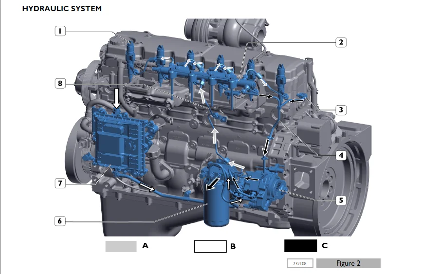
HYDRAULIC SYSTEM………………………………………………………………………………………… 42
Fuel system diagram………………………………………………………………………………….. 43
SUPPLY SYSTEM COMPONENTS…………………………………………………………………………………….. 45
Fuel filter…………………………………………………………………………………………….. 45
Mechanical supply pump…………………………………………………………………………………… 46
Normal operating condition……………………………………………………………………………. 46
Output overpressure condition…………………………………………………………………………. 46
Air bleeding conditions………………………………………………………………………………. 47
High pressure pump BOSCH CP3.3……………………………………………………………………………. 47
High-pressure pump internal structure………………………………………………………………….. 49
LUBRICATION CIRCUIT…………………………………………………………………………………………. 50
General information……………………………………………………………………………………… 50
LUBRICATION CIRCUIT COMPONENTS……………………………………………………………………………. 53
Oil pump……………………………………………………………………………………………. 53
Heat exchanger………………………………………………………………………………………. 54
Oil pressure regulator valve………………………………………………………………………….. 55
Engine oil sump……………………………………………………………………………………… 56
Oil filter………………………………………………………………………………………….. 57
OIL VAPOUR RECIRCULATION SYSTEM………………………………………………………………………………. 58
General information……………………………………………………………………………………… 58
Description…………………………………………………………………………………………. 58
OIL VAPOUR RECIRCULATION SYSTEM COMPONENTS…………………………………………………………………. 59
Blow-by filter………………………………………………………………………………………. 59
COOLING CIRCUIT…………………………………………………………………………………………….. 59
General information……………………………………………………………………………………… 59
COOLING SYSTEM DIAGRAM……………………………………………………………………………….. 60
COOLING CIRCUIT COMPONENTS……………………………………………………………………………….. 61
Water pump………………………………………………………………………………………….. 61
Thermostat………………………………………………………………………………………….. 62
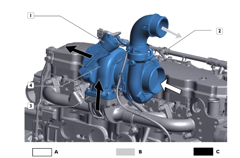
TURBOCHARGING………………………………………………………………………………………………. 64
Description…………………………………………………………………………………………….. 64
………………………………………………………………………………………………….. 64
Turbocharger……………………………………………………………………………………………. 64
Turbocharger actuator……………………………………………………………………………………. 66
Electric/electronic system………………………………………………………………………………………….. 69
ELECTRIC EQUIPMENT……………………………………………………………………………………………… 71
Location of engine electrical components………………………………………………………………………. 73
ECU……………………………………………………………………………………………………….. 74
EDC17CV41 electronic control unit…………………………………………………………………………. 74
EDC system operation…………………………………………………………………………………….. 76
Pin out………………………………………………………………………………………………… 79
Pin Out – Engine side………………………………………………………………………………… 79
Pin Out – Vehicle side……………………………………………………………………………….. 82
ENGINE SIDE WIRING………………………………………………………………………………………….. 85
Cable on engine…………………………………………………………………………………………. 85
Wire diagram……………………………………………………………………………………………. 88
VEHICLE SIDE WIRING…………………………………………………………………………………………. 90
Wire diagram……………………………………………………………………………………………. 90
ELECTRONIC COMPONENTS……………………………………………………………………………………….. 91
Electro-injectors……………………………………………………………………………………….. 91
Beginning of injection……………………………………………………………………………….. 91
End of injection…………………………………………………………………………………….. 91
Engine speed sensor on timing system………………………………………………………………………. 92
………………………………………………………………………………………………….. 92
Engine speed sensor (crankshaft sensor)……………………………………………………………………. 93
………………………………………………………………………………………………….. 93
Air temperature and boost pressure sensor………………………………………………………………….. 94
Engine oil temperature and pressure sensor…………………………………………………………………. 94
Fuel pressure sensor…………………………………………………………………………………….. 95
Coolant temperature sensor……………………………………………………………………………….. 96
Fuel temperature sensor………………………………………………………………………………….. 97
High pressure fuel pump dosing unit……………………………………………………………………….. 99
Preheating resistor (Grid Heater)………………………………………………………………………….100
Scheduled maintenance……………………………………………………………………………………………….103
SCHEDULED MAINTENANCE……………………………………………………………………………………………105
Introduction………………………………………………………………………………………………..107
Checks and scheduled maintenance procedures…………………………………………………………………….107
CHECKS TO PERFORM DURING PERIOD OF USE…………………………………………………………………………108
Check engine oil level……………………………………………………………………………………108
Checking the engine coolant level………………………………………………………………………….109
Engine visual inspection………………………………………………………………………………….109
Check the condition of the auxiliary device belt (part not supplied by FPT)…………………………………….109
Check the condition of the exhaust duct(s)………………………………………………………………….110
Check air filter and support are clean (part not supplied by FPT)……………………………………………..110
PERIODICAL MAINTENANCE……………………………………………………………………………………….111
Draining the water from the fuel prefilter (if present)………………………………………………………111
Change engine oil………………………………………………………………………………………..111
Engine oil filter removal – refitting………………………………………………………………………113
Replace the fuel pre-filter (if present)……………………………………………………………………114
Fuel filter removal-refitting……………………………………………………………………………..114
Visually inspect turbocharger……………………………………………………………………………..115
Removal – Refitting of the auxiliary device belt (part not supplied by FPT)…………………………………….116
Change blow-by filter…………………………………………………………………………………….117
Air filter replacement (part not supplied by FPT)……………………………………………………………118
Radiator cleaning (part not supplied by FPT)………………………………………………………………..118
UNSCHEDULED MAINTENANCE………………………………………………………………………………………118
Tappet clearance adjustment……………………………………………………………………………….118
Replace engine coolant……………………………………………………………………………………120
Removal-refitting of the main engine components………………………………………………………………………..121
Removal – refitting of main components…………………………………………………………………………….123
Removal – Refitting of the auxiliary device belt (part not supplied by FPT)………………………………………..125
Removal – Refitting of the fan control pulley…………………………………………………………………..126
Removal – refitting of the automatic belt tensioner……………………………………………………………..127
Water pump removal-refitting………………………………………………………………………………….129
Engine cable removal-refitting………………………………………………………………………………..131
Turbocharger removal-refitting………………………………………………………………………………..132
Engine oil filter removal – refitting………………………………………………………………………….135
Heat exchanger removal-refitting………………………………………………………………………………136
Oil sump removal-refitting……………………………………………………………………………………137
Removal – refitting of the fuel pipes………………………………………………………………………….139
Fuel filter removal-refitting…………………………………………………………………………………142
Removal – Refitting vehicle fuel filter mount…………………………………………………………………..143
Removal – refitting of the high pressure pump…………………………………………………………………..145
Common rail removal-refitting…………………………………………………………………………………148
Removal – refitting of the EDC 17 control unit………………………………………………………………….150
Change blow-by filter………………………………………………………………………………………..152
Tappet cover replacement……………………………………………………………………………………..153
Removal – refitting the electro-injector wirings………………………………………………………………..155
Removal – refitting of the rocker arm unit……………………………………………………………………..157
Heater Removal and Refitting………………………………………………………………………………….160
Intake manifold removal-refitting……………………………………………………………………………..161
Removal – refitting of the electro-injectors……………………………………………………………………163
Exhaust manifold removal-refitting…………………………………………………………………………….166
Cylinder head removal-refitting……………………………………………………………………………….168
Removal – refitting of the damper flywheel……………………………………………………………………..171
Removal – refitting of the crankshaft drive pulley………………………………………………………………172
Removal – refitting of the crankshaft front cover seal ring………………………………………………………174
Removal – refitting of the engine flywheel……………………………………………………………………..176
Removal – refitting of the crankshaft rear seal ring…………………………………………………………….178
General mechanical overhaul………………………………………………………………………………………….181
General mechanical overhaul ……………………………………………………………………………………..183
General mechanical overhaul of the engine on the bench…………………………………………………………..185
Technical specifications…………………………………………………………………………………………….269
Technical specifications ………………………………………………………………………………………..271
DATA – INSTALLATION CLEARANCES………………………………………………………………………………..273
Assembly clearances and data………………………………………………………………………………273
TIGHTENING TORQUES…………………………………………………………………………………………..277
tightening torques……………………………………………………………………………………….277
Equipment………………………………………………………………………………………………………….283
TOOLS………………………………………………………………………………………………………….285
Safety regulations………………………………………………………………………………………………….295
SAFETY REGULATIONS………………………………………………………………………………………………297
Standard safety precautions…………………………………………………………………………………..299
Accident prevention………………………………………………………………………………………….299
During maintenance…………………………………………………………………………………………..299
Protection of the environment…………………………………………………………………………………300
DESCRIPTION:
Tigercat FPT N67 Tier 2 ENGINE Service & Repair Manual – PDF DOWNLOAD
INTRODUCTION :
This document provides data, specifications, instructions and methods to perform repair interventions on the assembly and its components. Anyhow, this document is addressed to qualified and specialised personnel. Before performing any intervention, check that the document relating to the vehicle model on which the intervention is being performed is available and also make sure that all accident prevention devices, including but not limited to, goggles, helmet, gloves, shoes, as well as work equipment, lifting and transport equipment, etc., are available and efficient, and also make sure that the unit is in safety conditions for intervention.
- Carrying out interventions which fully comply with the indications given here, as well as the use of the specific equipment indicated, ensures repair interventions are carried out correctly, timings are respected and the operator’s safety is safeguarded.
- Each repair intervention must be finalised to the recovery of functionality, efficiency and safety conditions that are provided by FPT. Each intervention on the unit aimed at a modification, alteration or other which has not been authorised by FPT relieves FPT of any liability, and, in particular, where the assembly is covered by a warranty, each intervention will immediately invalidate the warranty.
- FPT declines any liability for repair work. FPT is available to provide any information necessary for the execution of the interventions and to provide instructions for any cases and situations not covered in this publication. The data contained in this issue may not be up-to-date due to possible modifications made by the Manufacturer for technical or commercial reasons, or to adaptations required by laws in force in different countries.
- In the event of discordance between the information in this publication and the actual assembly, please contact the FPT network before performing any interventions. The complete or partial reproduction of the text or illustrations herein is forbidden. Manuals for repairs are split into Sections, each one of which is marked by a numeral; the contents of these sections are indicated in the general table of contents.
- Sections with mechanical contents include technical data, tightening torque collections, tool lists, overhauls at the bench, diagnostics and scheduled maintenance In the electrical/electronic system section there are the descriptions of the electric network and the electronic systems of the assembly, wiring diagrams, electrical characteristics of components and the component codes. The appendix provides a list of the general safety regulations which all operators, whether installers or maintenance technicians, must comply with to prevent any serious injury.
IMAGES PREVIEW OF THE MANUAL:
TIGERCAT FPT N67 TIER 2 ENGINE SERVICE & REPAIR MANUAL – PDF DOWNLOAD:
PLEASE NOTE:
- This is the same manual used by the DEALERSHIPS to SERVICE your vehicle.
- The manual can be all yours – Once payment is complete, you will be taken to the download page from where you can download the manual. All in 2-5 minutes time!!
- Need any other service / repair / parts manual, please feel free to contact us at [email protected] . We may surprise you with a nice offer
S.V
![Tigercat ВАЛОЧНО-ПАКЕТИРУЮЩАЯ МАШИНА 860C 870C L870C РУКОВОДСТВО ПО ОБСЛУЖИВАНИЮ - [Russian]](https://heydownloads.com/wp-content/uploads/2022/01/Tigercat-ВАЛОЧНО-ПАКЕТИРУЮЩАЯ-МАШИНА-860C-870C-L870C-РУКОВОДСТВО-ПО-ОБСЛУЖИВАНИЮ-1-300x215.webp)
![Tigercat 860C 870C L870C ВАЛОЧНО-ПАКЕТИРУЮЩАЯ МАШИНА РУКОВОДСТВО ПО ОБСЛУЖИВАНИЮ - [Russian]](https://heydownloads.com/wp-content/uploads/2022/01/Tigercat-860C-870C-L870C-ВАЛОЧНО-ПАКЕТИРУЮЩАЯ-МАШИНА-РУКОВОДСТВО-ПО-ОБСЛУЖИВАНИЮ-3-300x219.webp)