
Tigercat T250B Track Loader Service Manual 2009 PDF Repair Guide
Original price was: $39.95.$23.95Current price is: $23.95.
Complete Tigercat T250B Track Loader Service Manual dated March 2009, covering serial 250T0501 and up. Full hydraulic, pilot, electrical, anti-stall, track drive, boom, swing, grapple and delimber/slasher service procedures with pressure settings, torque charts and schematics in one downloadable PDF.
Description
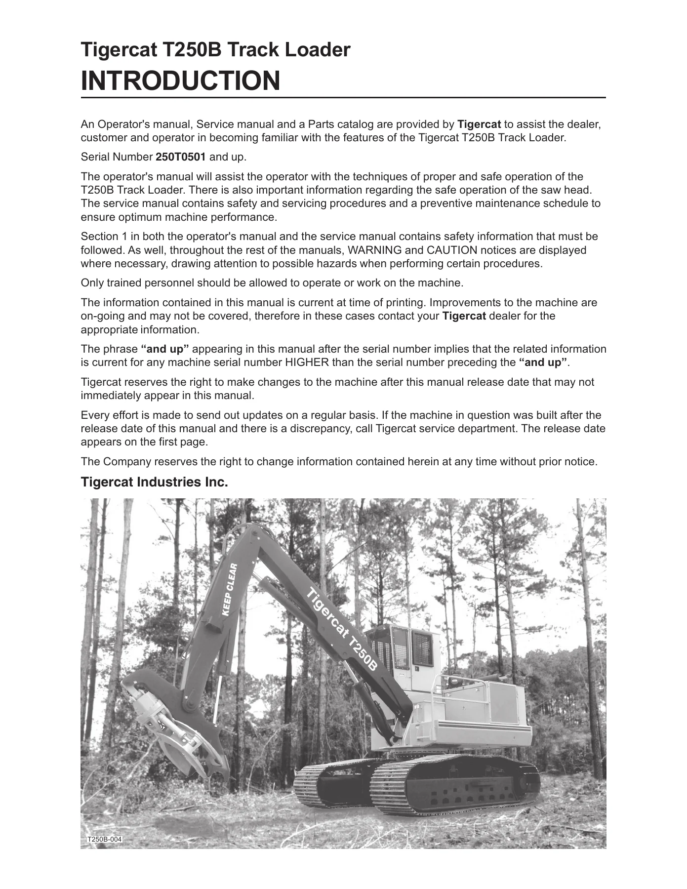
The Tigercat T250B Track Loader Service Manual is the full workshop reference for the T250B track loader, issued by Tigercat Industries Inc. with a March 2009 publication date and covering serial number 250T0501 and up. This Tigercat T250B Track Loader Service Manual 2009 PDF Repair Guide is written for the technician who has to actually diagnose, adjust, repair and maintain the machine rather than for someone reading a sales sheet. Every major system is broken out into its own section, from the load sensing hydraulic circuit through the pilot system, the 24 volt electrical network, the anti-stall engine control, the track drive, boom, swing and grapple, right through to the optional delimber/slasher installation.
File Details
- Manual type: Service Manual
- Brand: Tigercat Industries Inc.
- Model: T250B Track Loader
- Serial number coverage: 250T0501 and up
- Publication date: March 2009
- Language: English
- File format: PDF
- Page count: 176 pages
Chapters Covered
- Introduction and serial number identification
- Non-Approved Field Product Changes — policy, approved options, weight considerations, warranty implications
- Safety — operating safety precautions, servicing safety precautions, fluid injection injury, lightning safety awareness, fire prevention and dry chemical cleanup
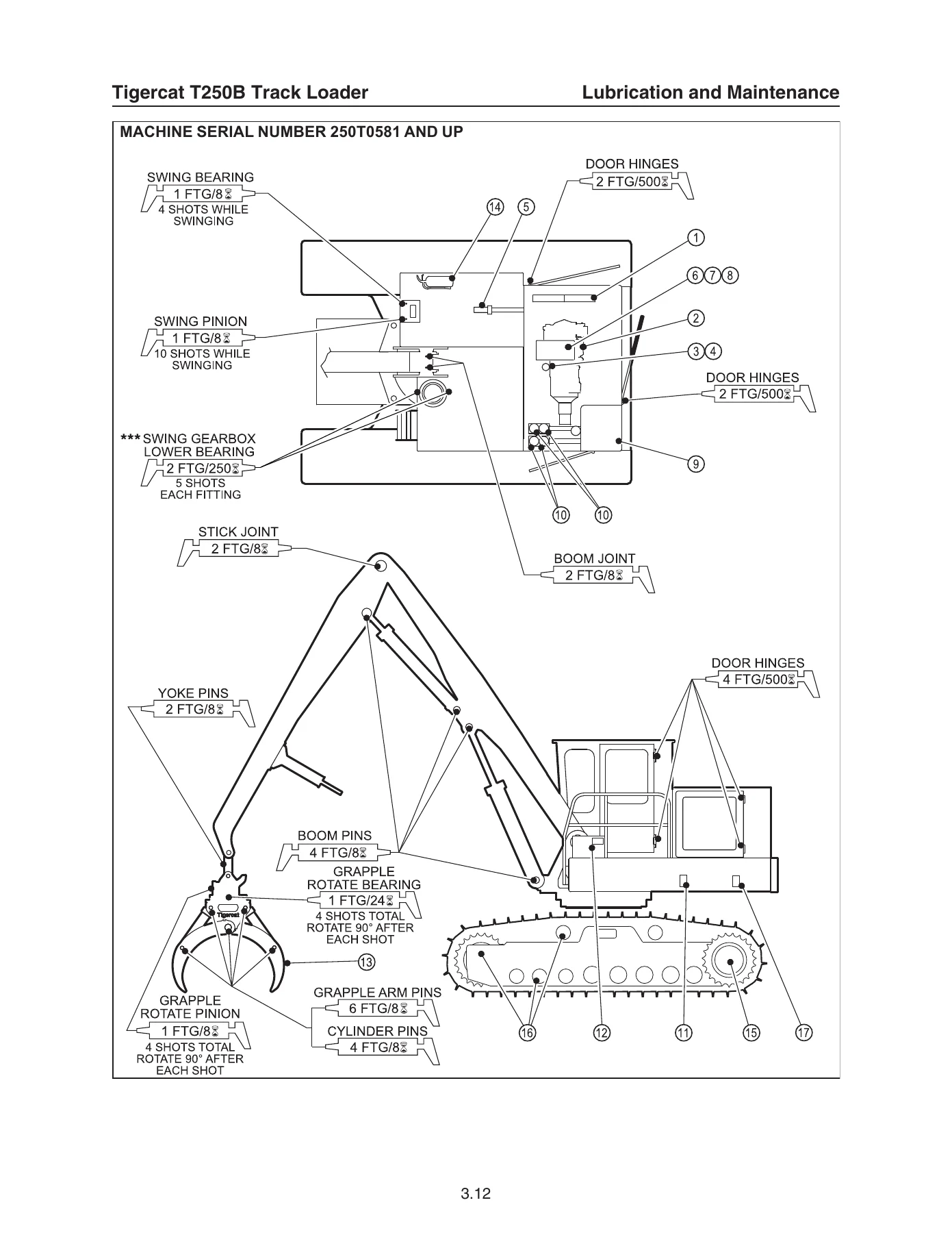
- Lubrication and Maintenance — preventive maintenance schedule, oil sampling program and collection procedures, approved hydraulic oils, lubrication and service points, hydraulic oil return filters, pilot pressure filter, case drain strainer, air cleaner maintenance, air conditioning, hydraulic pressurization system
- Hydraulic System / Load Sense Control — hydraulic oil reservoir, main pump and swing pump, main control valve, load sensing principles, open centre vs closed centre, margin pressure, high pressure limiting control
- Pilot System — pilot manifold, pilot supply valve, pilot pressure filter, joysticks and foot pedals, pilot pressure setting
- Electrical, Gauges and Alarms — PowerView display module, gauges and warning lights, fuse and relay panel, instrument panel wiring
- Engine Start and Stop — start circuit description and start circuit schematics
- Engine Anti-Stall — horsepower limiting control, Plus 1 control module, controller blink codes, fault finding procedures
- Track Drive — foot pedal control valve, track control valves, travel and drive enable solenoid valves, drive motor and gearbox, track speed set-up, straight travel, track sag measurement and adjustment, undercarriage torque values, wear limits
- Boom Functions — boom valve spool sections, pressure compensation, port reliefs, hoist and stick relief valve settings
- Swing — swing pump, swing motor, swing drive gearbox, swing bearing seal and backlash adjustment, swing bearing wear limits
- Grapple — grapple control valves, grapple connections to boom, open/close and rotate pressure settings
- Delimber / Slasher (optional installation) — delimber open/dump valve, saw cut and saw retract circuits, delimber/slasher electrical schematic and relay troubleshooting
- Torque charts — general torque specifications, four-bolt split flange assembly torque, Parker and Eaton Aeroquip assembly torque
- Electrical schematics — four sheets covering the machine harness
What This Workshop Manual Actually Gives You
This Tigercat T250B service manual is structured so that a technician can move from a symptom to a measured result. The load sense hydraulic section explains how the variable displacement main pump reacts to work port pressure, what margin pressure means, and how to read the difference between the PX and PL test ports on the main valve inlet section. Margin pressure is set to 375 psi and the main pump POR to 4500 psi, and the manual walks through the differential gauge connection and the adjusting screw on the main pump controller step by step.
Pressure values appear throughout as checkable figures rather than vague guidance. The hoist and stick port reliefs sit at 4875 psi, the swing high pressure reliefs at 5100 psi in each direction, grapple open at 2500 psi, grapple close at 3500 psi and grapple rotate at 1750 psi. Pilot pressure is regulated at 500 psi and swing pump charge pressure at 350 psi, with the test port locations called out and photographed so there is no guesswork about where the gauge goes.
Hydraulics, Electrical and Undercarriage in Detail
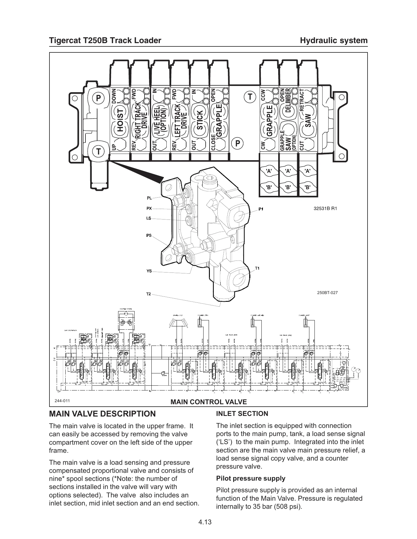
The hydraulic coverage alone makes this Tigercat T250B Track Loader Service Manual 2009 PDF Repair Guide worth having on the laptop. It documents the main control valve as a nine-section plus mid-inlet mono-block unit, identifies the inlet, mid-inlet and end sections, explains the load signal copy valve and counterpressure valve, and describes the difference between the cylinder spools used on the hoist, stick and grapple sections and the motor spools used on track drive, grapple rotate and saws. Filter service is covered in full, including the water absorbing return filter, the return manifold restriction indicator and the correct gasket installation for both square section and O-ring type filter heads.
The electrical side includes the PowerView display module keypad functions, the meaning of the amber warning and red shutdown LEDs, low engine oil pressure and coolant temperature thresholds, and the fuse and relay panel layout with every circuit identified. Four electrical schematic sheets cover the machine harness, the start circuit is drawn out in both at-rest and run conditions, and the anti-stall section includes the Plus 1 control module connector pin assignments together with the red LED blink code table for PWM coil, pilot pressure sender, hydraulic oil temperature sender and J1939 CAN BUS faults.
Undercarriage work is covered with real numbers. The manual sets out the track speed procedure for 12 rpm in low and 28 rpm in high, the begin of regulation pressure check, brake release pressure setting at 500 psi, and the torque-turn method for track shoe bolts at 220 lbf/ft plus one third turn with a checking torque of 450 lbf/ft. Wear limits for grousers, track link height, bushing outside diameter and both roller sizes are tabulated so a worn undercarriage can be assessed rather than guessed at.
Safety, Maintenance and Optional Attachments
Safety content is substantial and practical, covering the servicing safety precautions, the fluid injection injury warning that applies to both diesel fuel and hydraulic systems operating above 3000 psi, pneumatic grease gun hazards, lightning safety awareness for forestry crews, and a detailed fire prevention and dry chemical cleanup section. The preventive maintenance schedule runs from every 8 hours through 125, 250, 500, 1000 and 2000 hour intervals, with the oil sampling program that Tigercat requires during the warranty period laid out alongside it.
For machines fitted with the optional delimber or slasher, the manual includes the delimber open/dump valve with its internal orifice, the pilot operated three-way valve that diverts flow between the top saw and slasher saw circuits, the delimber relay circuit troubleshooting sequence, and the pressure settings for saw cut and saw retract. The grapple section covers both open/close and rotate, including the note that Rotobec HD and Hultdins grapples use a 3000 psi rotate setting instead of the standard 1750 psi.
Why This Tigercat T250B Service Manual Matters
With this Tigercat T250B Track Loader Service Manual 2009 PDF Repair Guide you can set margin pressure correctly, diagnose a sluggish or jerky boom, adjust track speed for straight travel, set swing reliefs, service the hydraulic return filters and pilot filter, trace an anti-stall fault through the blink codes, check the track drive begin of regulation, adjust swing bearing backlash, measure undercarriage wear against the published limits and torque every major fastener to specification. Working from the correct pressures and procedures is the difference between a repair that holds and a repeat failure — and on a forestry loader, guessing at hydraulic settings is expensive.
IMAGES PREVIEW
Delivery is instant. The file is a downloadable PDF that arrives immediately after payment, with no shipping and no waiting for a disc. Keep it on a laptop or tablet in the service truck, print the pages you need for the job, and work from the same document for every T250B service task that comes through the shop.



Reviews
There are no reviews yet.