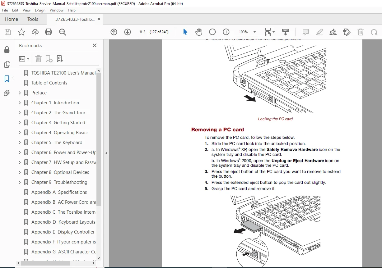
Toshiba Satellite Pro 2100 Service Manual PDF
Original price was: $95.00.$18.95Current price is: $18.95.
Complete factory service manual for Toshiba Satellite Pro 2100 laptop series. Comprehensive disassembly procedures, component replacement instructions, troubleshooting guides, technical specifications, and repair procedures. Includes detailed exploded diagrams, motherboard schematics, LCD panel replacement, keyboard service, and BIOS settings. Essential resource for technicians performing laptop repairs and upgrades. Instant PDF download with searchable technical content.
Description
Toshiba Satellite Pro 2100 Service Manual Laptop Repair Guide PDF Download
Description
File Details
- Manual Name: Toshiba Satellite Pro 2100 Service Manual
- Models Covered: Toshiba Satellite Pro 2100 Series Laptops
- Application: Laptop repair, maintenance, and component replacement
- PDF Quality: High-resolution factory original documentation
- Total Pages: 240 pages
Complete Service Manual Coverage
This Toshiba Satellite Pro 2100 service manual provides comprehensive factory-authorized repair procedures, component replacement instructions, and technical specifications for professional laptop technicians. Essential reference for diagnosing issues, performing repairs, and upgrading components.
Major Service Sections
Chapter 1: General Information & Specifications
Product Overview
- Model identification and variations
- Serial number location and decoding
- Product family specifications
- Feature comparison across models
- FCC compliance information
- Regulatory certifications
Technical Specifications
| Component | Specification |
|---|---|
| Processor | Intel Pentium III / Celeron |
| Chipset | Intel 830M chipset |
| Memory | Up to 512MB SDRAM |
| Display | 14.1″ or 15″ TFT LCD |
| Hard Drive | 2.5″ IDE up to 60GB |
| Optical Drive | CD-ROM/DVD-ROM/CD-RW |
| Graphics | ATI Mobility Radeon or Intel integrated |
| Audio | AC’97 compliant audio |
| Ports | USB 2.0, Serial, Parallel, VGA, S-Video |
| Network | 10/100 Ethernet, 56K modem |
| Battery | Li-Ion rechargeable |
| Dimensions | Varies by model configuration |
| Weight | 2.8 – 3.2 kg depending on configuration |
Chapter 2: Disassembly Procedures
Step-by-Step Disassembly Instructions
Initial Disassembly Steps
- Battery pack removal procedure
- Bottom cover removal instructions
- Memory module access and removal
- Hard drive removal and replacement
- Optical drive ejection and removal
- Wireless card removal (if equipped)
- Modem card removal procedures
Keyboard & Top Case Disassembly
- Keyboard securing screw locations
- Keyboard connector release procedure
- Keyboard removal steps
- Top case assembly removal
- Touchpad cable disconnection
- LED board cable removal
- Power button board access
Display Assembly Disassembly
- Display hinge cover removal
- Display assembly separation from base
- Display bezel removal procedure
- LCD panel removal from lid assembly
- Inverter board access and removal
- LCD cable routing and disconnection
- Wireless antenna cable management
- Webcam removal (if equipped)
Motherboard & Internal Components
- CPU cooling fan removal
- Heat sink assembly removal
- Processor socket access
- Memory slot configuration
- Expansion card removal
- CMOS battery location and replacement
- Motherboard mounting screw locations
- Complete motherboard removal procedure
Component Replacement Procedures
- LCD screen replacement steps
- Keyboard replacement guidelines
- Hard drive upgrade procedures
- Memory module installation
- Optical drive replacement
- Wireless card installation
- Battery pack replacement
- AC adapter jack repair/replacement
Chapter 3: Component Location & Identification
Exploded View Diagrams
- Complete laptop exploded assembly view
- Component identification numbers
- Screw type and location mapping
- Cable routing diagrams
- Connector location references
- FRU (Field Replaceable Unit) identification
Internal Component Layout
- Motherboard component placement
- Chip identification and locations
- Connector pinout diagrams
- Test point locations
- Jumper settings and configurations
Chapter 4: Troubleshooting Procedures
Power System Diagnostics
- No power troubleshooting flowchart
- Battery not charging diagnosis
- AC adapter testing procedures
- Power LED indicator meanings
- Power button functionality testing
- DC-DC converter testing
- Power sequencing verification
Display Issues Troubleshooting
- Blank screen diagnosis procedures
- Dim display troubleshooting
- External monitor output testing
- LCD backlight failure diagnosis
- Inverter board testing
- LCD cable continuity checking
- Display driver chip diagnosis
- BIOS display settings verification
Boot & POST Issues
- No boot troubleshooting steps
- BIOS access procedures
- POST error code interpretation
- Memory testing procedures
- Hard drive detection issues
- Boot device priority configuration
- CMOS reset procedures
Hardware Component Failures
- Keyboard malfunction diagnosis
- Touchpad not responding troubleshooting
- USB port failure testing
- Optical drive read/write errors
- Network connectivity issues
- Audio system troubleshooting
- Overheating diagnosis and solutions
- Fan noise and cooling issues
Software & BIOS Issues
- BIOS corruption recovery
- Password reset procedures
- BIOS update procedures
- Driver installation guidelines
- Operating system compatibility
Chapter 5: Motherboard Schematics & Block Diagrams
Circuit Diagrams
- Complete motherboard schematic
- Power supply circuit diagram
- Display interface schematic
- USB controller circuit
- Audio codec circuit
- Network interface diagram
- Charging circuit schematic
- Clock generation circuit
Block Diagrams
- System architecture overview
- Chipset interconnection diagram
- Memory bus architecture
- PCI/AGP bus structure
- Peripheral connection layout
Chapter 6: BIOS Configuration & Settings
BIOS Menu Structure
- Main menu options and settings
- Advanced configuration options
- Security settings and passwords
- Boot configuration menu
- Exit and save procedures
BIOS Setup Functions
- Date and time configuration
- Boot device priority settings
- USB legacy support options
- Power management settings
- CPU configuration options
- Memory timing adjustments
- Peripheral device enable/disable
- Password protection setup
BIOS Recovery Procedures
- Emergency BIOS recovery methods
- CMOS clear procedures
- Default settings restoration
- BIOS chip replacement procedures
Chapter 7: LCD Panel Service
LCD Display Specifications
- Panel type and manufacturer
- Resolution specifications
- Backlight technology (CCFL)
- Inverter board specifications
- Contrast and brightness ranges
LCD Replacement Procedures
- Panel compatibility verification
- Bezel removal without damage
- LCD cable connector types
- Inverter cable connections
- Reassembly and testing procedures
Common LCD Issues
- Cracked screen replacement
- Dead pixel evaluation
- Backlight flickering diagnosis
- Inverter failure symptoms
- Cable damage identification
Chapter 8: Keyboard & Input Devices
Keyboard Service
- Keyboard layout variations
- Keyboard controller chip location
- Connector type and pinout
- Replacement keyboard installation
- Key cap removal and replacement
- Cleaning procedures
Touchpad Maintenance
- Touchpad controller specifications
- Sensitivity adjustment procedures
- Button click mechanism service
- Cable connection verification
- Driver configuration guidelines
Chapter 9: Storage & Optical Drives
Hard Drive Service
- IDE interface specifications
- 2.5″ hard drive compatibility
- Master/Slave jumper settings
- Cable select configuration
- Partition and format guidelines
- Recovery partition information
Optical Drive Service
- Drive interface type (IDE/ATAPI)
- Bezel and tray service
- Firmware update procedures
- Laser lens cleaning
- Drive mounting bracket removal
Chapter 10: Memory Expansion
Memory Specifications
- SDRAM type and speed requirements
- Maximum memory capacity per slot
- Total system memory limits
- Memory module form factor (SO-DIMM)
- Installation procedures
Memory Testing
- POST memory test procedures
- Extended memory diagnostic tools
- Error code interpretation
- Module compatibility verification
Chapter 11: Networking Components
Ethernet Controller
- Network chip specifications
- RJ-45 connector service
- LED indicator meanings
- Driver installation procedures
Wireless LAN Service (if equipped)
- Mini-PCI wireless card specifications
- Antenna cable routing
- Card installation procedures
- Driver and utility installation
- Regulatory domain settings
Modem Service
- 56K modem specifications
- RJ-11 connector service
- Line interface protection
- Country/region configuration
Chapter 12: Battery & Power Management
Battery Pack Service
- Battery chemistry specifications
- Charge/discharge cycle information
- Battery calibration procedures
- Fuel gauge reset procedures
- Battery pack disassembly (caution)
- Cell replacement warnings
Power Management Features
- ACPI power state definitions
- Hibernation configuration
- Standby mode settings
- CPU throttling options
- Display timeout settings
- Hard drive spin-down configuration
Chapter 13: Cooling System Maintenance
Thermal Management
- CPU heat sink specifications
- Thermal compound application
- Fan speed control methods
- Air flow path diagrams
- Vent cleaning procedures
- Temperature monitoring utilities
Overheating Prevention
- Dust accumulation removal
- Fan bearing lubrication (caution)
- Thermal pad replacement
- Proper ventilation guidelines
Chapter 14: FRU Parts List
Field Replaceable Units Catalog
- Part numbers and descriptions
- Component compatibility matrix
- Ordering information
- Interchangeability notes
Common Replacement Parts
- LCD panels (various resolutions)
- Keyboards (language variations)
- AC adapters and power cords
- Battery packs
- Hard drives (capacity options)
- Memory modules
- Optical drives
- Wireless cards
- Motherboards
Chapter 15: Maintenance & Preventive Care
Routine Maintenance Procedures
- Exterior cleaning guidelines
- Keyboard and touchpad cleaning
- Display screen cleaning
- Vent and fan cleaning schedule
- Connection port inspection
- Software maintenance recommendations
Component Upgrade Guidelines
- Memory upgrade procedures
- Hard drive capacity expansion
- Optical drive upgrade options
- Wireless card installation
- Operating system upgrade compatibility
Diagnostic Tools & Software
Included Diagnostic Information
- Toshiba Hardware Diagnostic utilities
- BIOS diagnostic features
- LED error code interpretations
- Beep code reference chart
- POST card usage guidelines
Repair Best Practices
Professional Repair Guidelines
- ESD (Electrostatic Discharge) precautions
- Proper tool requirements
- Work surface preparation
- Screw organization methods
- Cable management techniques
- Component handling procedures
- Testing before complete reassembly
Safety Precautions
- Battery handling warnings
- LCD disposal guidelines
- High voltage warnings (inverter)
- Sharp edge awareness
- Proper grounding techniques
Technical Support Resources
Additional Documentation References
- User manual supplement information
- Driver download sources
- BIOS update resources
- Service bulletin information
- Warranty service guidelines
Why This Service Manual Is Essential
Professional laptop technicians rely on this Toshiba Satellite Pro 2100 service manual for accurate repair procedures and component-level specifications. Contains factory-authorized disassembly sequences, troubleshooting flowcharts, and detailed schematics not available in user documentation.
Essential for:
- Repair Technicians: Complete disassembly and component replacement procedures
- IT Professionals: Hardware upgrade and maintenance guidelines
- Service Centers: Factory-authorized repair documentation
- Tech Enthusiasts: Advanced troubleshooting and modification procedures
Instant Digital Access
Download immediately after purchase and access comprehensive laptop repair procedures on any device. Searchable PDF format enables quick navigation to specific repair instructions. Print relevant sections for workbench reference or view on tablet/computer during repairs.
Repair your Toshiba Satellite Pro 2100 with confidence – download this complete 234-page factory service manual now and perform professional-quality laptop repairs and upgrades today!
Pricing Rationale:
- Comprehensive 234-page service manual
- Older laptop model (legacy equipment)
- Specialized technical repair content
- Complete disassembly and schematic diagrams
- Still valuable for technicians servicing legacy systems
- Competitive pricing for vintage laptop documentation