
Toyota 8FBMKT20-30 8FBMT25-35 Electric Forklift Repair Manual – CE360-5
Original price was: $39.95.$24.95Current price is: $24.95.
Complete Toyota repair manual for 8FBMKT20, 8FBMKT25, 8FBMKT30, 8FBMT25, 8FBMT30 and 8FBMT35 electric forklifts. Covers battery systems, control system, motors, drive axle, rear axle, brakes, masts, hydraulics, SAS system and full troubleshooting with diagnostic codes. CE360-5.
Description
About This Toyota Electric Forklift Repair Manual
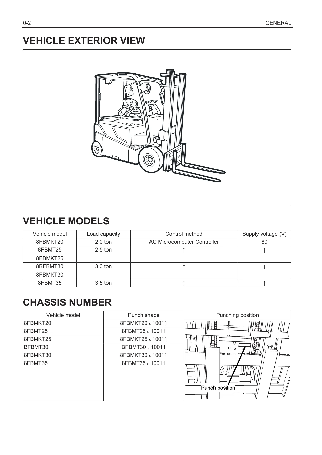
This is the complete Toyota repair manual for the 8FBMKT20, 8FBMKT25, 8FBMKT30, 8FBMT25, 8FBMT30 and 8FBMT35 electric forklift models, document number CE360-5. It covers 2.0, 2.5, 3.0 and 3.5 ton trucks equipped with the AC Microcomputer Controller and 80V supply. The manual is organized into 19 major sections that take a technician from general vehicle information through every major system on the truck, including full disassembly, inspection and reassembly procedures with tightening torques, component weights, and specification tables throughout.
File Details
- Manual type: Repair Manual
- Brand: Toyota
- Models covered: 8FBMKT20, 8FBMKT25, 8FBMKT30, 8FBMT25, 8FBMT30, 8FBMT35
- Document number: CE360-5
- Language: English
- Page count: Approximately 736 pages
- File format: PDF
Chapters Covered
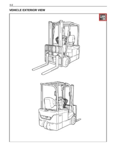
- 0. General — Vehicle exterior view, models, chassis number, how to use the manual, operating tips, suspension rope angles, component weights, towing, electrical inspection, SAS notes, tightening torque tables, lubricants and fluids, periodic maintenance
- 1. Battery — Lead battery, Toyota lithium battery, MIDAC lithium battery, battery compartment, standard service values, multi-display functions, battery management parameters, indicator troubleshooting
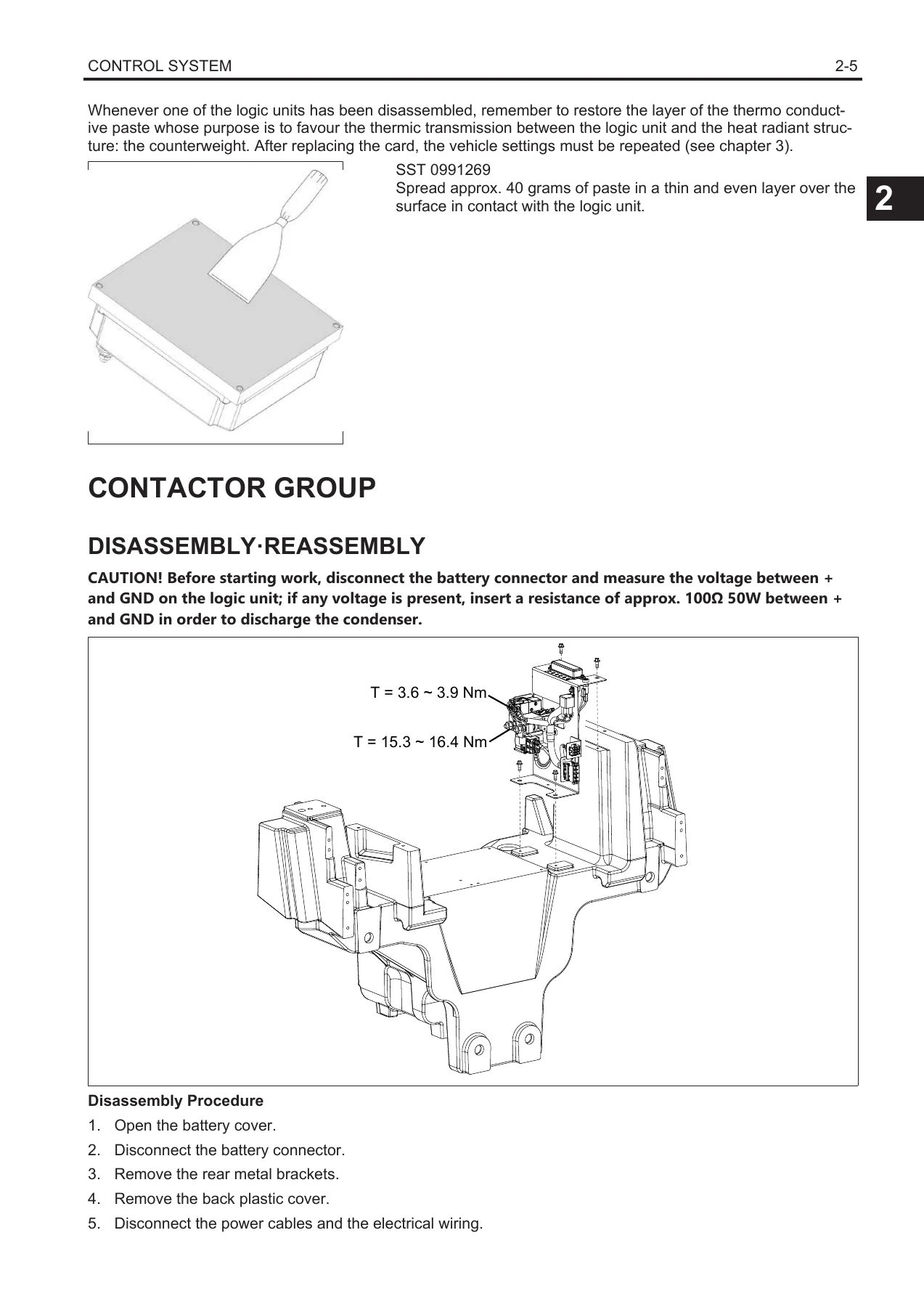
- 2. Control System — General, CAN-BUS connection specifications, logic units, contactor group, MCB card, display, 24-12V fuse card, armrest card, steering potentiometer, tilt angle potentiometer, mast pressure sensor, mast height switch, accelerator potentiometer, minilever potentiometer, joystick potentiometer
- 3. Multi-Function Display — General, menu map, operator menu, administrator menu, mask menu, analyzer, tuning, option set, matching, others menu, forced ignition
- 4. Troubleshooting — Connector check, wire harness inspection, insulation check, motor winding check, temperature sensor check, system configuration, diagnostic codes list, error code procedures
- 5. Motor — Drive motor, temperature sensor, pump motor, encoder replacing
- 6. Drive Unit & Front Axle — General, components, front axle assembly
- 7. Rear Axle — Rear axle assembly, rear axle hub, cast articulated joint, rear axle cylinder
- 8. Power Steering System — General, steering column, orbitrol, priority valve
- 9. Brake — General, brake unit, checking brakes wear, parking brake, negative brake version, brake unit negative brake version
- 10. Frame — Components, battery cover unit, counterweight, driver’s seat, overhead guard, fuses
- 11. Material Handling System — Hydraulic diagram, hydraulic circuit, components, oil tank, oil filter and air breather pipe, hydraulic oil, natural drop test, oil leak test
- 12. Masts — Mast, fork carriage assembly and mast removal, mast group, lifting bracket, chain and chain pulley group, adjusting the mast, standard for oversize roller, chains, fork
- 13. Cylinders — Lifting cylinders, tilting cylinders
- 14. Oil Pump — General, adjusting oil flow rate, components, disassembly and assembly
- 15. Oil Control Valve — Hydraulic diagram, components, specifications, troubleshooting, disassembly and assembly, pressure relief valve adjustment
- 16. SAS System — General, components, repair work, hand grip position correction valve, tilt angle sensor, load sensor, oscillation lock cylinder, adjustment, standard vehicle status, vehicle modification warnings
- 17. Main Options — Converters, height selector, bump sensor, DHU, keypad, flash and rotating lamp, work spotlights, combined lights, floating cabin
- 18. Appendix — Components, wiring diagrams for all models including lithium battery version and floating overhead guard version
The Toyota 8FBMKT20-30 8FBMT25-35 repair manual goes well beyond routine maintenance. It provides the full diagnostic framework for the AC Microcomputer Controller system, including the multi-function display menus used to read fault codes, monitor I/O signals in real time, and perform active tests on steering and swing lock valves. The troubleshooting chapter alone spans over 170 pages, listing every diagnostic code the controllers can generate, the conditions that trigger each code, and the step-by-step checks needed to isolate the fault — from low battery voltage and contactor failures to encoder errors, thermal protection trips and CAN-bus communication loss. For the battery, both lead-acid and lithium options are documented, including battery management parameters, indicator calibration and troubleshooting for the BDI system.
Mechanical coverage is equally detailed. The motor chapter gives disassembly procedures for the drive and pump motors with component weights, torque values and bearing/seal fitting instructions. The drive unit and front axle section covers removal of the complete axle assembly, oil top-up and draining for the negative brake version. The rear axle chapter includes the cast articulated joint, hub bearings, and the oscillation lock cylinder used by the SAS system. Brake coverage documents the wet disk brake unit with seven disks, self-adjust mechanism, parking brake cable adjustment, and the negative brake version with its hydraulic release procedure for towing. Mast sections cover V, FV, FSV, FW and FSW configurations, chain adjustment, roller selection and the shimming procedure needed to prevent uneven lifting from the twin lift cylinders.
Hydraulic and SAS content rounds out the manual. The material handling chapter provides the full hydraulic circuit, oil tank removal, filter service, and the natural drop and oil leak tests used to evaluate cylinder and valve condition. The oil control valve chapter includes a detailed troubleshooting matrix for lifting, lowering and tilting problems, plus the pressure relief valve adjustment procedure. The SAS system chapter explains the active rear stabilizer, active mast function control and active steering synchronizer — with sensor calibration procedures for tilt angle, load sensor, wheel angle and yaw rate that must be performed after any related repair.
What This Manual Enables You to Do
With this Toyota repair manual, a technician or fleet workshop can diagnose and repair the full range of systems on these electric forklifts. That includes reading and clearing diagnostic codes through the multifunction display, calibrating the accelerator, steering and mast sensors after replacement, rebuilding the drive and pump motors, servicing the wet brake units, replacing mast rollers and chains, adjusting the tilt cylinders for even lifting, and troubleshooting the SAS system when the stability controls behave unexpectedly. Every procedure is written with the torque values, clearances and special tools called out so the work can be done to Toyota’s specifications rather than by guesswork.
Correct procedures and specifications matter on electric forklifts because the controllers, sensors and hydraulic valves are closely integrated. A steering potentiometer that is not calibrated correctly, a mast that lifts unevenly because the cylinder rod shims are wrong, or a SAS sensor that is out of range can all cause fault codes that stop the truck from working. This manual gives you the reference values and step-by-step methods to get each system back within specification, whether you are working on a single truck or maintaining a fleet.
IMAGES PREVIEW
Delivered as an instant PDF download after payment, the manual requires no shipping and no waiting. It can be viewed on any device — laptop, tablet or smartphone — and printed pages can be taken straight to the machine. The file is fully text-based and searchable, so you can jump directly to the section or diagnostic code you need rather than paging through hundreds of sheets.
Reviews
There are no reviews yet.