TOYOTA Forklift 7PLL24 Service Manual – PDF DOWNLOAD
$28.95
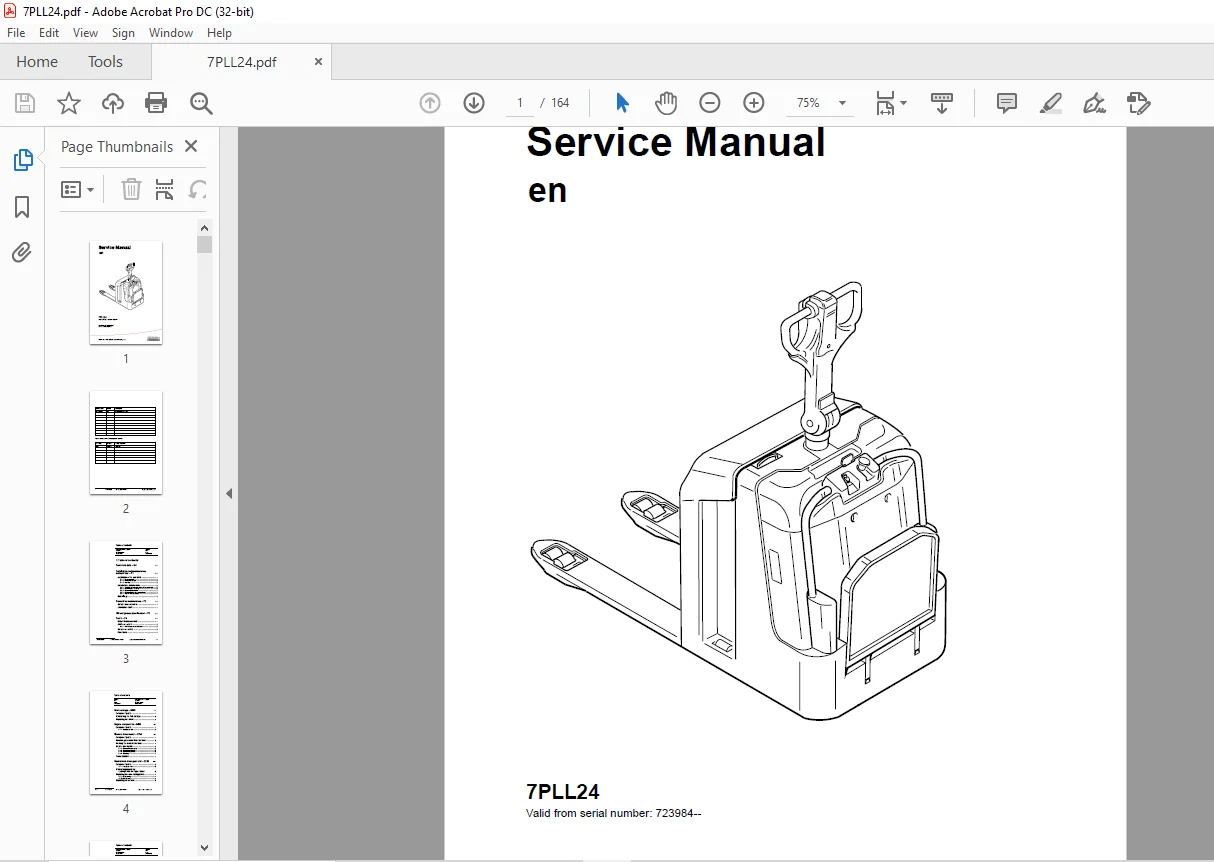
TOYOTA Forklift 7PLL24 Service Manual – PDF DOWNLOAD
Description
TOYOTA Forklift 7PLL24 Service Manual – PDF DOWNLOAD
FILE DETAILS:
TOYOTA Forklift 7PLL24 Service Manual – PDF DOWNLOAD
Language : English
Pages : 164
Downloadable : Yes
File Type : PDF
IMAGES PREVIEW OF THE MANUAL:
TABLE OF CONTENTS:
TOYOTA Forklift 7PLL24 Service Manual – PDF DOWNLOAD
Valid from serial number: 723984–
Order number: 222996-040
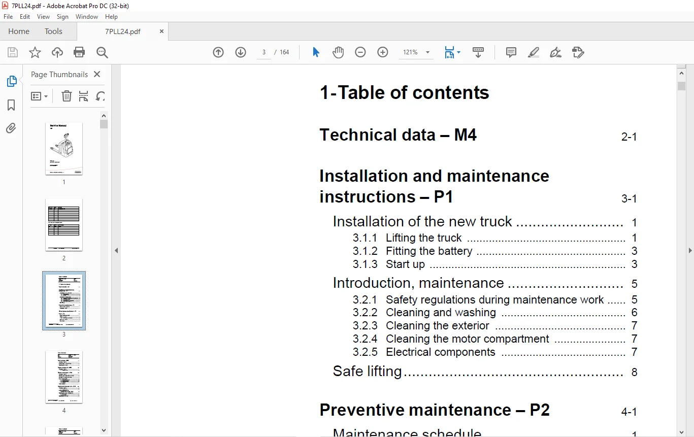
1- Table of contents 3
2- Technical data – M4 11
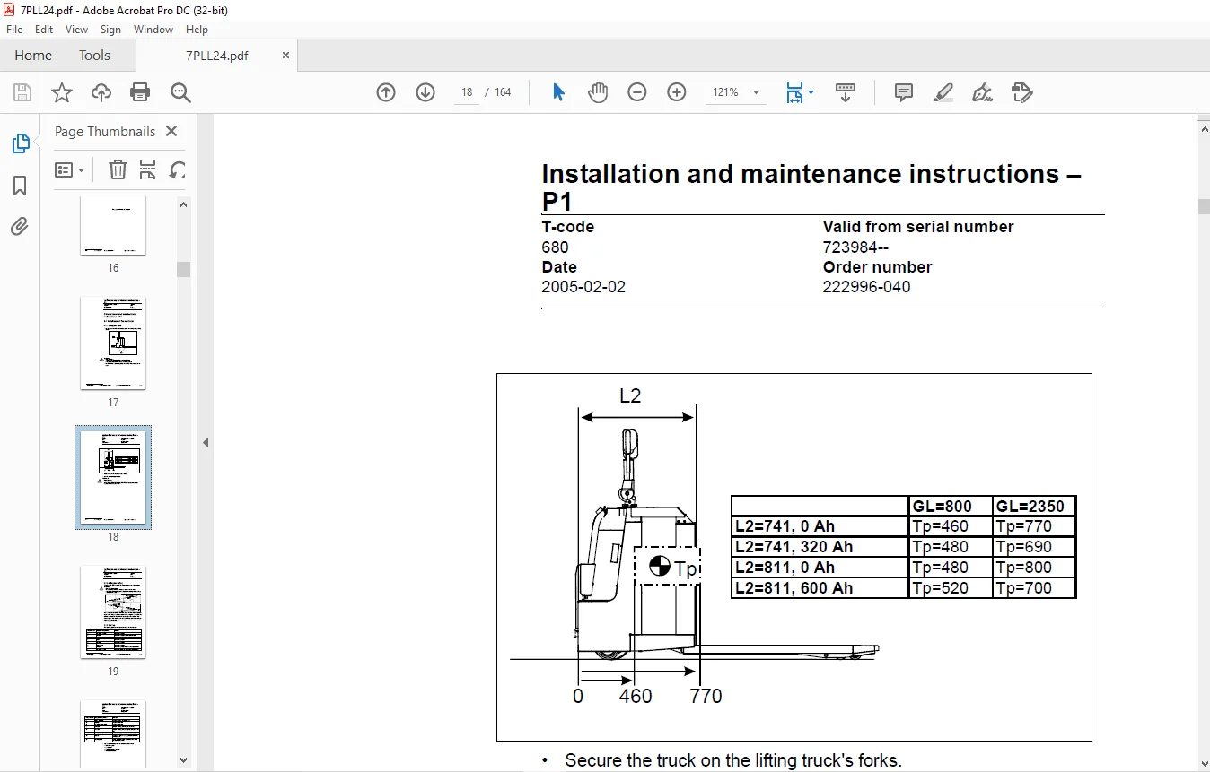
3- Installation and maintenance instructions – P1 17
31 Installation of the new truck 17
311 Lifting the truck 17
312 Fitting the battery 19
313 Start up 19
32 Introduction, maintenance 21
321 Safety regulations during maintenance work 21
322 Cleaning and washing 22
323 Cleaning the exterior 23
324 Cleaning the motor compartment 23
325 Electrical components 23
33 Safe lifting 24
4- Preventive maintenance – P2 25
41 Maintenance schedule 25
42 Lubrication chart 31
5- Oil and grease specification – P3 33
6- Tools – P4 35
61 Super Seal connectors 35
62 AMP connectors 36
621 AMP Connectors, 040 series 37
63 Molex connectors 37
64 Other tools 38
7- Fork carriage – 0380 39
71 Component parts 39
72 Dismantling the fork carriage 41
73 Replacing the rollers 43
8- Engine suspension- 0450 45
81 Component parts 45
811 Component List 46
9- Electric drive motor – 1760 47
91 Component parts 47
92 Removing the motor from the truck 49
93 Refitting the motor in the truck 50
94 Service and repairs 51
941 Dismantling the motor 51
942 Dismantling N-side 52
943 Dismantling D-side 52
944 Cleaning 53
95 Technical data 53
10- Mechanical drive gear unit – 2550 55
101 Component parts 56
1011 Technical data 57
102 Dismantling/Assembly Leakage from the upper cover 57
103 Replacing the drive shaft gasket 58
1031 Dismantling 58
1032 Assembling 59
104 Replacing wheel bolt 60
11- Electromagnetic brake – 3370 61
111 Component parts 61
112 Dismantling 62
1121 Inspection 62
113 Assembling 63
114 Manual release of the brake 63
115 Adjustment 63
1151 Adjusting the play 63
12- Steering system – 4000 65
121 Component parts, mechanical steering 65
122 Component parts, servo steering (Option) 68
1221 Steering axle, servo steering (Option) 69
123 Adjustment, steering 73
1231 Adjusting the steering servo 73
1232 Adjusting the steering chain 73
124 Component parts, tiller arm 74
125 Adjustment, tiller arm 75
1251 Adjusting the brake microswitch 75
126 Tiller arm handle 76
127 Dismantling/Assembly, buttons 78
Change from ignition key to keyboard (2) 78
Change from keyboard to ignition key (2) 78
1271 Replacing the signal button/switch (9, 10) 79
1272 Replacing the lift/lower button (13) 79
1273 Replace the pushbutton (16) 80
13- Electrical systems – 5000 81
131 Electrical parts 81
132 Symbol list and electrical diagram 83
1321 Electrical wiring diagram 1(5) 85
1322 Electrical wiring diagram 2(5) 86
1323 Electrical wiring diagram 3(5) 87
1324 Electrical wiring diagram 4(5) 88
1325 Electrical wiring diagram 5(5) 89
1326 Electrical wiring diagram Servo (Option) 90
133 Functional description 91
1331 Starting the truck 91
1332 Driving without using platform and gates, speed £ 6 km/h 91
1333 Driving from platform without using gates,speed £ 6 km/h 91
1334 Driving from platform and using gates, speed ³ 8 km/h 91
1335 Neutral speed reduction 91
1336 Neutral speed reduction on slopes 92
1337 Braking 92
1338 Lifting the forks 92
1339 Lowering the forks 92
13310 Horn 92
134 Hour meter 93
135 Error codes 93
136 Parameters105
1361 Driver parameters105
1362 Parameter description106
Parameter 1106
Parameter 2106
Parameter 3106
Parameter 4106
Parameter 5106
1363 Service parameters107
1364 Parameter description108
Parameter 10108
Parameter 14109
Parameter 15 – Non-configurable option109
Parameter 16 – Configurable option #1109
Parameter 17 – Configurable option #2109
Parameter 18 – Configurable option #3109
Parameter 19 – Configurable option #4109
Option parameters109
General109
Parameter #15 Non-configurable options109
Changing non-configurable options110
Parameter #16 to 19 configurable optional functions111
Changing configurable optional functions111
Parameter 20116
Parameter 21116
Recommendation on parameter setting for freely ventilated batteries117
Instructions for verifying parameter setting118
Recommendation on parameter setting for valve- controlled batteries (VRLA)119
Instructions for verifying parameter setting120
Parameter 22120
Parameter 25120
Parameter 28120
Parameter 39121
Login method and driver parameter access121
Expanded keypad – General121
Expanded keypad – Programming121
Service indication123
137 Part numbers126
138 Transistor panel126
1381 General126
139 Diagnostic and troubleshooting127
1391 Error codes and troubleshooting127
1392 Resetting errors128
1393 Safety128
1310 Technical specifications – Curtis 1243129
14- Hydraulic, pneumatic – 6000131
141 General131
1411 Hydraulic diagram131
1412 Symbol list132
142 Adjustments133
1421 Adjustment of the pressure limit valve133
143 Cleaning the filter134
15- PowerTrak cylinder – 6680135
151 Component parts135
152 Dismantling the PowerTrak cylinder136
1521 Replacing the gaskets in the PowerTrak cylinder137
153 Dismantling/assembling the ground pressure springs138
1531 Component parts138
1532 Dismantling139
1533 Assembling139
1534 Setting and sealing139
1535 Sealing140
16- Control/computer equipment – 8700141
161 General141
162 Connection141
163 Layout142
1631 Main program screen142
1632 Nodes142
1633 Icons143
1634 Tool buttons and menu bar143
1635 Information window144
1636 Status bar144
164 Connection function144
165 Disconnection function144
166 Downloading program function145
1661 Normal downloading (truck with key)145
1662 Normal downloading (truck with keypad)145
1663 Emergency downloading (truck with keypad)146
1664 Downloading in old versions of logic card146
1665 Emergency downloading (truck with keypad)146
167 Truck report function147
168 Parameters function148
169 Diagnostics function148
1691 Representation of signal colours149
1692 “Tiller arm” tab149
1693 “Drive Controller” tab (transistor regulator – travel)150
1694 “Pump controller” tab (transistor regulator – pump)151
1695 “EPS” steering servo tab152
1610 Other menu functions153
16101 Save to file153
16102 Download from file153
16103 Reset CAN adapter153
16104 Delete error code log153
16105 Reset hour meter153
16106 Read error code log154
16107 Adjust date and time154
16108 Adjusting the hour meter on older cards154
16109 Help154
About the TruckCom application154
161010 Exit154
1611 Specifications154
1612 Installation155
16121 Installation on a PC with Windows® 95/98155
16122 Installation on a PC with Windows XP/ 2000156
16123 Installation on a PC with Windows NT161
16124 In case of communication problems with CAN161
16125 To uninstall161
S.V 26/02/2025
![1994 Toyota Celica 1.8L 4-CYL VIN [A] Service Manual - PDF DOWLOAD](https://heydownloads.com/wp-content/uploads/2022/11/1994-Toyota-Celica-1.8L-4-CYL-VIN-A-Service-Manual-2-300x217.webp)