
Toyota Land Cruiser Heavy Duty Repair Manual Chassis Body PDF Download
Original price was: $47.95.$28.95Current price is: $28.95.
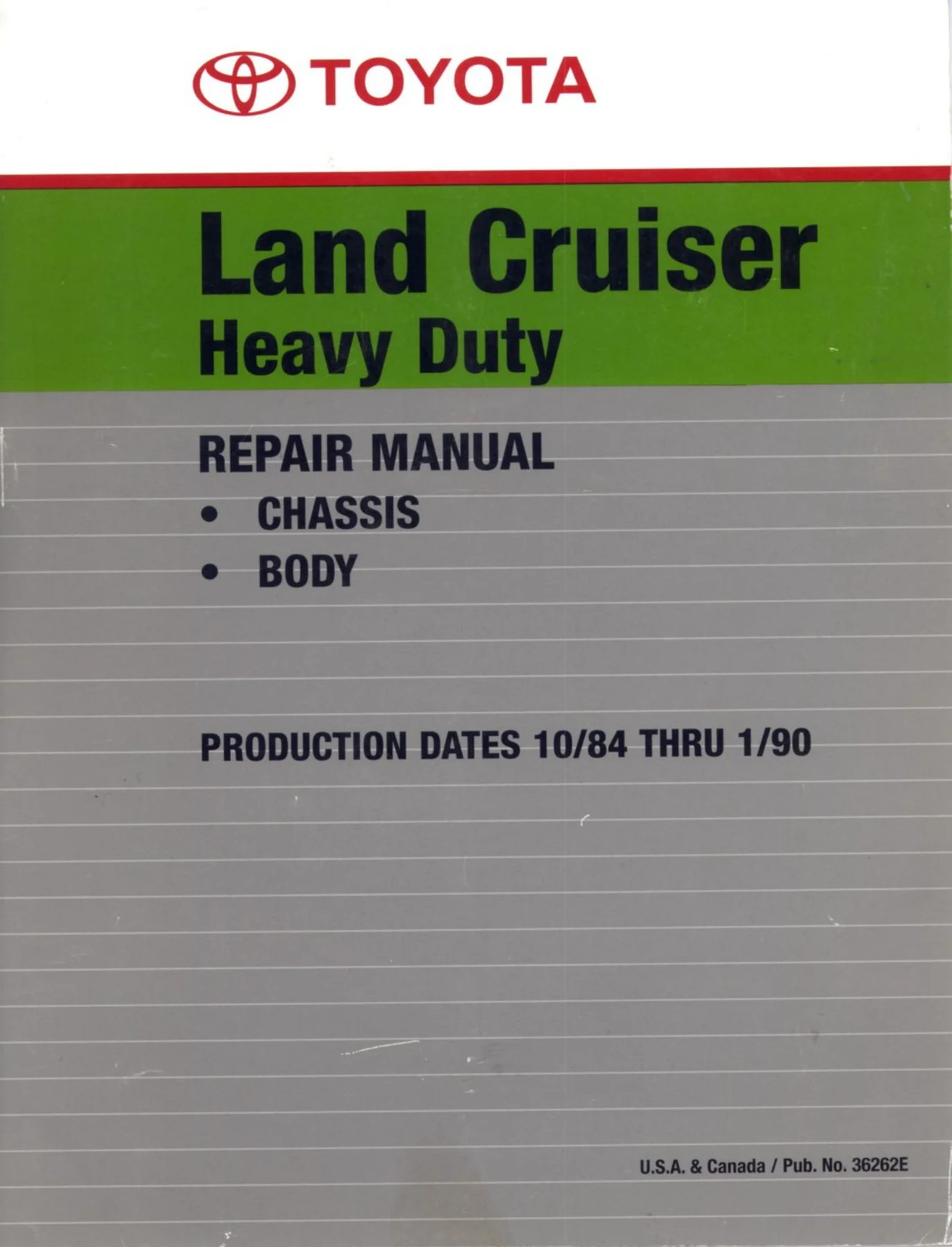
Toyota land cruiser heavy duty repair manual for FJ/BJ/HJ Heavy-Duty series, 720 pages covering chassis, body, brakes, steering, A/C, specifications and wiring. Instant PDF download.
Description
Production dates 10/84 thru 1/90 and the FJ, BJ and HJ Heavy-Duty series are identified on this 720-page Toyota Land Cruiser repair manual for chassis and body. The manual applies to FJ 62, 70, 73, 75 series; BJ 60, 70, 73, 75 series; and HJ 60, 75 series, then covers the vehicle from clutch and transmissions through axles, brakes, steering, body electrical, body, winch, air conditioning, service specifications and wiring diagrams.
Toyota Land Cruiser Heavy Duty repair manual file details
- Manual type: Service / Workshop / Repair
- Brand/model: Toyota Land Cruiser (Heavy-Duty)
- Publication number: 36262E
- Production coverage: 10/84 thru 1/90
- Language: English
- Page count: 720
- File format: PDF
Applicable Heavy-Duty Land Cruiser series
- FJ 62, 70, 73, 75 series
- BJ 60, 70, 73, 75 series
- HJ 60, 75 series
The foreword also points to separate engine repair manuals for the 3F, 3B and 2H engines and to the A440L/A440F automatic-transmission repair manual. Within this volume, the focus is chassis and body service, with the transmission, transfer, propeller-shaft, axle, suspension, braking, steering, electrical, body and climate-control systems arranged as dedicated sections.
How repair information is presented
The introduction explains a step-by-step repair format. Major operations begin with an overview illustration that identifies components and shows how parts fit together; the procedure then states what to do, illustrates where to do it and provides detailed text including specifications and warnings. Troubleshooting tables connect symptoms with possible causes, remedies and page references, while specification values appear in the relevant procedures and again in the dedicated service-specifications section.
Identification pages show the vehicle identification number location on the cowl panel of the engine compartment and engine serial-number locations for the 3F, 3B and 2H engines. Lift and support diagrams cover 60 series, 70 series short, 73 series middle and 75 series long chassis, giving a useful workshop reference before underbody or axle work.
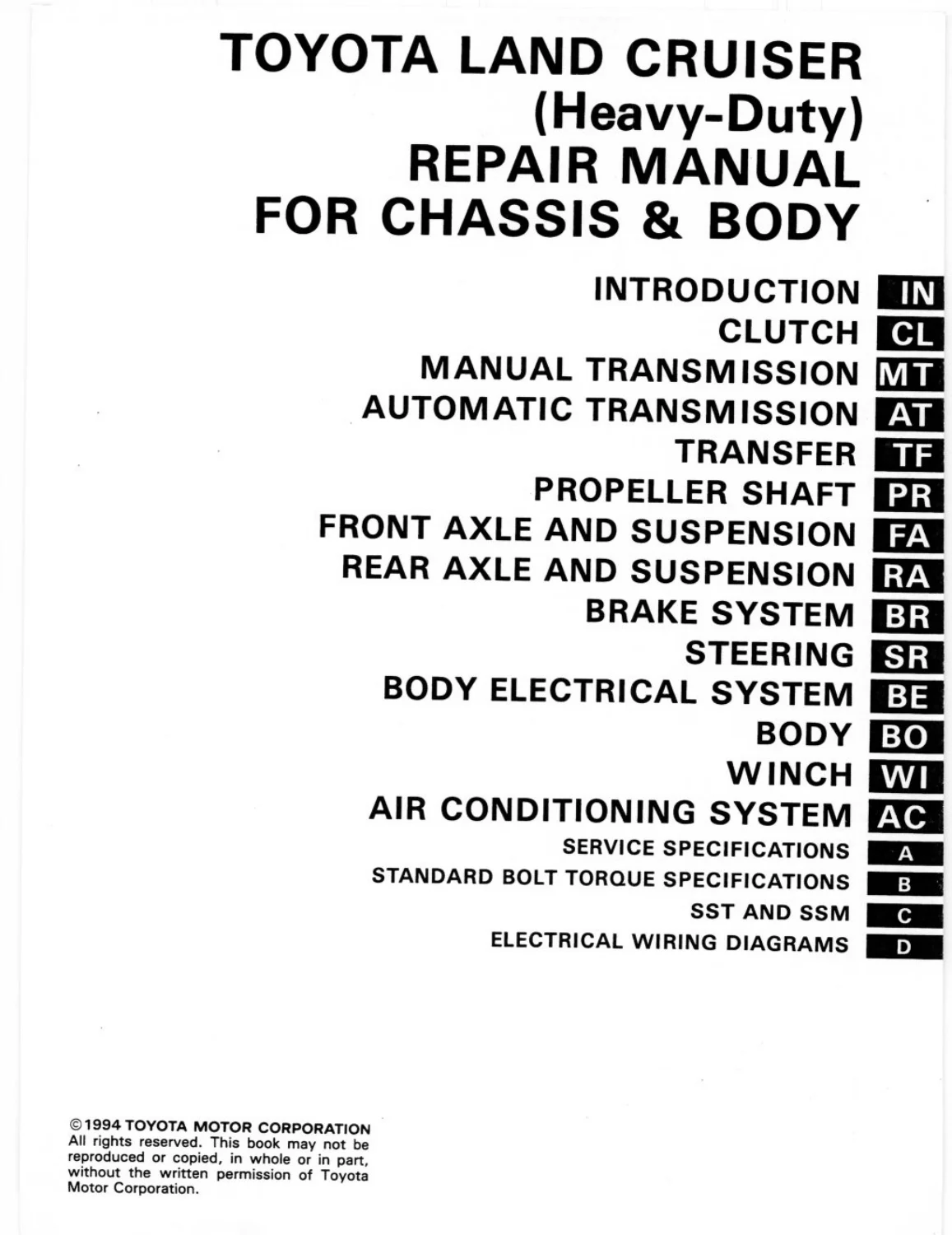
Chassis, body and electrical sections included
- Introduction
- how to use this manual
- identification information
- general repair instructions
- vehicle lift and support location
- abbreviations used
- Clutch
- troubleshooting
- check and adjustment of clutch pedal
- operational test of clutch booster
- bleeding of clutch system
- clutch master cylinder
- clutch booster
- clutch release cylinder
- clutch unit
- Manual Transmission
- manual transmission diagnosis and repair
- component removal/disassembly/inspection/assembly
- Automatic Transmission
- automatic transmission diagnosis
- hydraulic and mechanical checks
- removal and repair procedures
- Transfer
- transfer case service
- inspection and component procedures
- Propeller Shaft
- propeller shaft inspection
- flange connection and service procedures
- Front Axle and Suspension
- front axle
- front hub and bearings
- front suspension service
- Rear Axle and Suspension
- rear axle
- rear hub and bearings
- rear suspension service
- Brake System
- hydraulic brake system
- disc/drum service
- inspection and adjustment
- Steering
- steering system
- gear and linkage service
- inspection and adjustment
- Body Electrical System
- electrical components
- lighting and accessories
- switches and circuits
- Body
- body panels
- doors and fittings
- interior and exterior component service
- Winch
- winch system service
- Air Conditioning System
- air conditioning service
- component inspection and repair
- Service Specifications
- clutch
- transmission
- transfer
- propeller shaft
- axles and suspension
- brakes
- steering
- body electrical
- air conditioning
- Standard Bolt Torque Specifications
- standard torque reference
- SST and SSM
- special service tools
- special service materials
- Electrical Wiring Diagrams
- electrical wiring diagrams
Clutch, transmission and driveline work
The clutch section starts with troubleshooting and pedal checks, then moves through clutch-booster operation, bleeding, master-cylinder service, booster service, release-cylinder work and clutch-unit procedures. The manual-transmission, automatic-transmission and transfer sections provide drivetrain repair coverage, followed by propeller-shaft service. Front and rear axle/suspension chapters continue the mechanical sequence through hubs, bearings and suspension components.
Brake-system and steering chapters add fault finding, adjustment and component repair. The body electrical section is followed by the body chapter itself, with dedicated winch and air-conditioning sections later in the volume. For electrical work, the closing wiring-diagram section provides circuit reference after the mechanical and body service material.
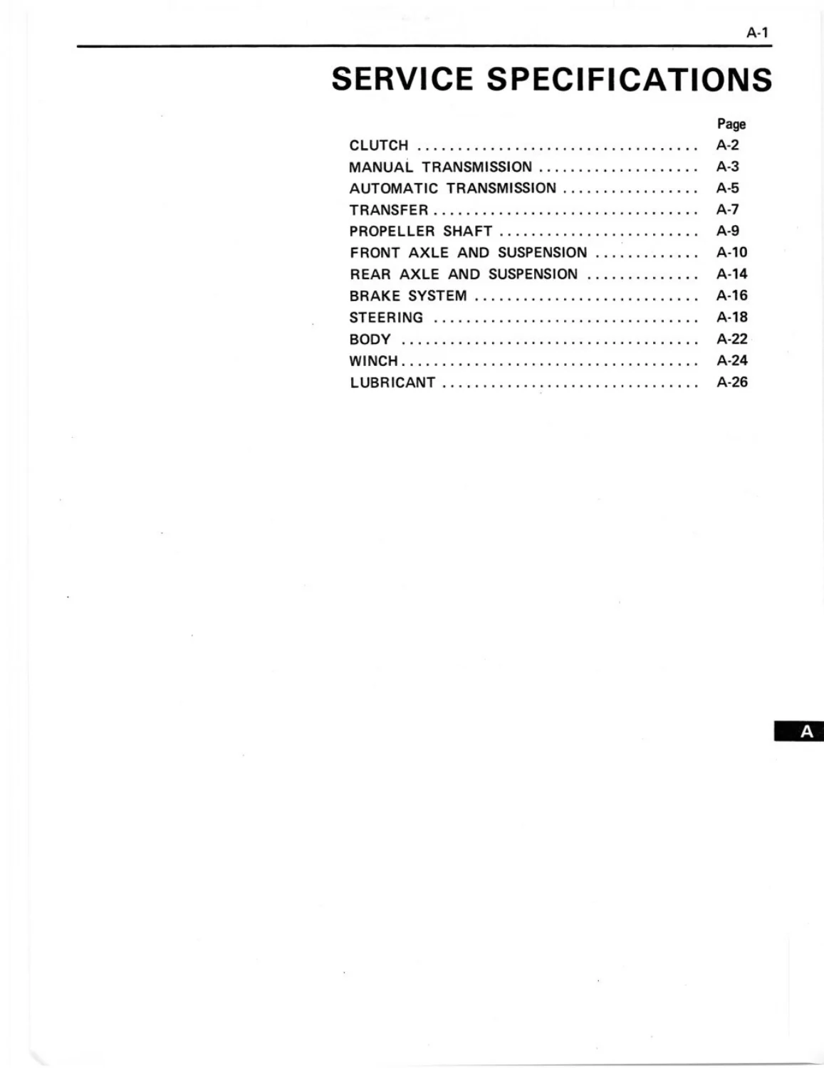
Specifications, standard torque and workshop references
A dedicated Service Specifications section begins near the end of the manual and consolidates values across the systems documented in the book. It is followed by Standard Bolt Torque Specifications and SST/SSM material for special service tools and special service materials. The repair-format example also shows a propeller-shaft flange-nut tightening value of 600–750 kg-cm (44–54 ft-lb, 59–73 N·m), illustrating how tightening data is integrated directly into repair steps.
The clutch troubleshooting pages demonstrate the manual’s diagnostic structure with conditions such as hard shifting, transmission jumping out of gear, clutch slipping, clutch grabbing/chattering, spongy pedal and clutch noise, each tied to likely causes and the relevant repair pages. This symptom-to-remedy organization is useful when the problem is known but the failed component is not yet confirmed.
Workshop instructions extend through inspection, reassembly and system checks
General repair instructions address non-reusable parts, pre-coated fasteners, sealants, electrical precautions and safe support of the vehicle. Those principles carry into the component chapters, where exploded component views identify assembly order and repair text gives removal, inspection, assembly and installation steps. The clutch pages, for example, combine fault diagnosis with pedal adjustment, booster checks, hydraulic bleeding and cylinder service rather than treating each item in isolation.
The same pattern continues through drivetrain, axle, brake and steering sections and into body electrical, body, winch and air-conditioning work. By the time the manual reaches Service Specifications, the technician has both the procedures and a consolidated place to verify service values. The Standard Bolt Torque section and electrical wiring diagrams then provide cross-system references for reassembly and circuit diagnosis.
Keep the correct Heavy-Duty chassis/body information at the workshop
For clutch adjustment, transmission and transfer work, propeller-shaft service, axle and suspension repairs, braking and steering diagnosis, body electrical work, air-conditioning procedures and wiring checks, the value of this manual is the model-specific sequence of illustrations, specifications and repair steps. Using the documented procedure helps keep component order, support points, tightening data and inspection criteria aligned with the Heavy-Duty Land Cruiser series named in the foreword.
After payment completes, the manual is delivered as an instant PDF download with no shipping and no waiting. Read it on a phone, tablet, laptop or workshop PC, and print the pages required for a particular repair, inspection or wiring task so the relevant instructions can stay beside the vehicle.
Reviews
There are no reviews yet.