
★ TRUSTED BY 321,897+ PROFESSIONALS WORLDWIDE
🏢
Trusted Business
Verified & Licensed
🛡️
Virus Free Files
100% Safe Downloads
🔒
Secure Payment
SSL Protected
Instant Delivery
Available Immediately
Sale!

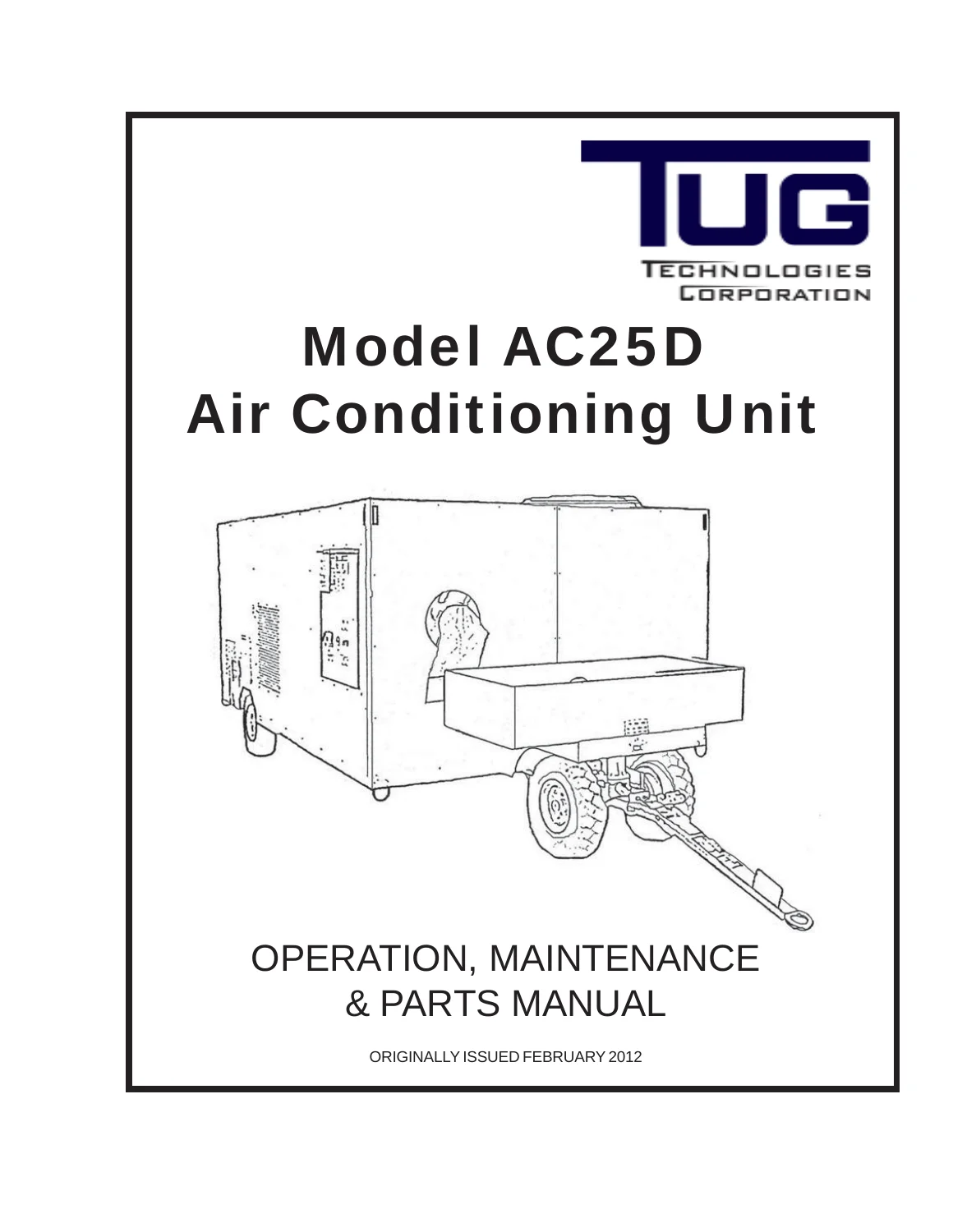
TUG Model AC25D Air Conditioning Unit Operation, Maintenance & Parts Manual

Original price was: $29.95.Current price is: $17.95.

Complete factory manual for the TUG Model AC25D ground support air conditioning unit, covering operation, maintenance, troubleshooting, overhaul data and the full illustrated parts list.

Instant PDF Download
Available immediately
💾
Save to Your Device
Download & keep forever
🛡️
Antivirus Scanned
100% virus-free
🌍
Trusted Worldwide
175,000+ customers

Description

TUG Model AC25D Air Conditioning Unit Operation, Maintenance & Parts Manual

This is the complete TUG Model AC25D Air Conditioning Unit Operation, Maintenance & Parts Manual, originally issued February 2012, covering the diesel-electric ground support cooling cart built by TUG Technologies of Kennesaw, Georgia. The AC25D delivers approximately 25 tons of cooling through a 12-inch flexible duct and is used to supply conditioned air to parked aircraft, powered by a Cummins QSB 4.5 110 HP diesel engine driving a 70 kVA, 3-phase, 480V generator.

  • Manual Type: Operation, Maintenance & Parts Manual
  • Brand/Model: TUG Model AC25D Air Conditioning Unit
  • Language: English (with additional-language technical inserts for select components)
  • Page Count: 858 pages
  • File Format: PDF, instant download
  • Document Number: CD386
  • Issue Date: Originally issued February 2012

Chapters Covered

  • Safety — general, warning statements, cautionary statements
  • Chapter 1: General Information and Operating Instructions
    • Description — system description and theory of operation
    • Operation — preparation for use and A/C operating procedures
    • Specifications — engine, battery, A/C unit, chassis, instrumentation, controls, accessories, fuel tank
    • Shipping — preparation for shipment and receiving
    • Storage — preparation for storage
  • Chapter 2: Maintenance
    • Servicing — cleaning, painting, engine oil/coolant/fuel specifications, consumable materials, periodic maintenance schedule, compressor/condenser section access
    • Troubleshooting — troubleshooting chart, schematics and wiring diagrams
  • Chapter 3: Overhaul — overhaul data for engine, generator and compressor
  • Chapter 4: Illustrated Parts List — using the parts list, ordering spare parts, illustrated parts list by assembly, numerical index, alphabetical index
  • Chapter 5: Appendices — periodic maintenance checklist, additional information & publications

Complete PDF Bookmark Tree

Complete Bookmarks

The complete bookmarks in the “TUG Model AC25D Air Conditioning Unit Operation, Maintenance & Parts Manual” are as follows:

INTRODUCTION – Model AC25D Air Conditioning Unit Manualp. 1
Record of Revisionsp. 3
List of Effective Pagesp. 4
Manual Table of Contentsp. 7
Copyright Noticep. 11
Introductionp. 12
Unit Identificationp. 13
Technical Assistancep. 14
Warranty Informationp. 15
How to Use this Manualp. 17
SAFETYp. 19
A. Generalp. 19
B. Warning Statementsp. 20
C. Cautionary Statementsp. 21
CHAPTER 1: GENERAL INFORMATION AND OPERATING INSTRUCTIONSp. 23
Chapter 1: Table of Contentsp. 23
Section 1: Descriptionp. 25
A. Generalp. 25
B. System Descriptionp. 25
C. Theory of Operationp. 30
Section 2: Operationp. 33
A. Generalp. 33
B. Preparation for Usep. 33
C. Air Conditioner Operating Proceduresp. 35
Section 3: Specificationsp. 37
A. Enginep. 37
B. Batteryp. 37
C. Air Conditioning Unitp. 37
D. Chassisp. 37
E. Instrumentationp. 37
F. Controlsp. 38
G. Accessories (ACU)p. 38
H. Fuel Tankp. 38
Figure 1-1 Electric Control Panelp. 39
Table 1-1 Electric Control Panelp. 40
Section 4: Shippingp. 41
A. Shippingp. 41
B. Preparation for Shipmentp. 41
C. Receivingp. 41
Section 5: Storagep. 43
A. Generalp. 43
B. Preparation for Storagep. 43
CHAPTER 2: MAINTENANCEp. 45
Chapter 2: Table of Contentsp. 45
Section 1: Servicingp. 47
A. Introductionp. 47
B. Generalp. 47
C. Cleaningp. 48
D. Paintingp. 48
E. Engine Oil Specifications & Recommendationsp. 48
F. Coolant Specifications & Recommendationsp. 49
G. Fuel Recommendations/Specificationsp. 50
H. Consumable Materialsp. 50
I. Periodic Maintenance Schedule:p. 51
J. Compressor/Condenser Section Accessp. 54
Section 2: Troubleshootingp. 59
A. Generalp. 59
B. Troubleshooting Chartp. 59
C. Schematics And Wiring Diagramsp. 60
Table 2-1. Troubleshootingp. 61
Figure 2-1 TUG Model AC25D Control Wiring Schematicp. 67
Figure 2-2 TUG Model AC25D Condenser Power Wiring Schematicp. 68
Figure 2-3 TUG Model AC25D Component Locationsp. 69
CHAPTER 3: OVERHAULp. 71
Chapter 3: Table of Contentsp. 71
Section 1: Overhaul Datap. 73
A. Introductionp. 73
B. Enginep. 73
C. Generatorp. 73
D. Compressorp. 73
CHAPTER 4: ILLUSTRATED PARTS LISTp. 75
Chapter 4: Table of Contentsp. 75
Section 1: Descriptionp. 77
A. Introductionp. 77
B. Using the Illustrated Parts Listp. 77
1. Figure and Index Numberp. 77
2. Part Numbersp. 78
3. Description and Quantityp. 78
4. Effectivityp. 79
C. Ordering Spare Partsp. 79
Section 2: Illustrated Parts Listp. 81
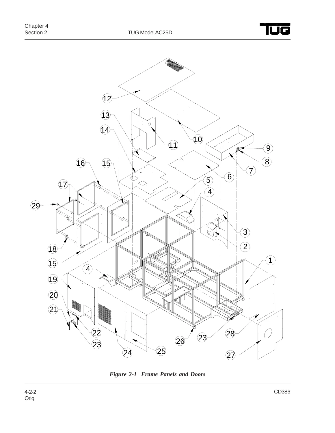
Figure 2-1 Frame Panels and Doorsp. 82
Table 2-1 Frame Panels and Doorsp. 83
Figure 2-2 Fifth Wheel Assemblyp. 84
Table 2-2 Fifth Wheel Assemblyp. 85
Figure 2-3 Rear Axle Installationp. 86
Table 2-3 Rear Axle Installationp. 87
Figure 2-4 Blower Assemblyp. 88
Table 2-4 Blower Assemblyp. 89
Figure 2-5 Distributor Hosep. 90
Table 2-5 Distributor Hosep. 91
Figure 2-6 Compressor Pipingp. 92
Table 2-6 Compressor Pipingp. 93
Figure 2-7 Condenser Unitp. 94
Table 2-7 Condenser Unitp. 95
Figure 2-8 Engine Assembly and Installationp. 96
Table 2-8 Engine Assembly and Installationp. 97
Figure 2-9 Fuel Systemp. 98
Table 2-9 Fuel Systemp. 99
Figure 2-10 Air Intake Assemblyp. 100
Table 2-10 Air Intake Assemblyp. 101
Figure 2-11 Cooling Assemblyp. 102
Table 2-11 Cooling Assemblyp. 103
Figure 2-12 Exhaust Systemp. 104
Table 2-12 Exhaust Systemp. 105
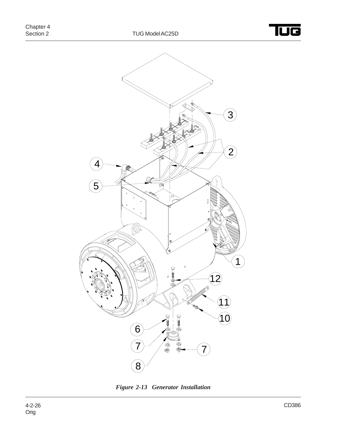
Figure 2-13 Generator Installationp. 106
Table 2-13 Generator Installationp. 107
Figure 2-14 Control Box Assemblyp. 108
Table 2-14 Control Box Assemblyp. 109
Figure 2-15 Control Panel Assemblyp. 110
Table 2-15 Control Panel Assemblyp. 111
Figure 2-16 Fuse Installationp. 112
Table 2-16 Fuse Installationp. 113
Figure 2-17 Battery Assemblyp. 114
Table 2-17 Battery Assemblyp. 115
Section 3: Numerical Indexp. 117
Section 4: Alphabetical Indexp. 125
CHAPTER 5: APPENDICESp. 133
Table of Contentsp. 133
Section 1: Periodic Maintenance Checklistp. 135
A. Daily Checksp. 135
B. 125 to 3000 Hour Checksp. 136
Section 2: Additional Information & Publicationsp. 137
A. Descriptionp. 137
OPERATION AND MAINTENANCE MANUAL FOR CUMMINS QSB4,5L, 110HP TIER III ENGINEp. 139
Table of Contentsp. 141
Important Reference Numbersp. 142
Section Ip. 143
Illustrationp. 149
General Safety Instructionp. 150
General Repair Instructionsp. 152
General Cleaning Instructionsp. 153
Acronyms and Abbreviationsp. 157
Section E – Engine Identificationp. 159
Engine Data Platep. 161
Engine Diagramsp. 164
Section FB – Industrial Featuresp. 171
Section Contentsp. 171
Fan Controlp. 173
Water-In-Fuel Sensorp. 173
Idle Shutdownp. 174
Accelerator Optionsp. 175
Intermediate Speed Control (ISC)p. 175
Switchable (Alternate) Torquep. 177
Multiple Unit Synchronizationp. 177
Hot Shutdown Monitorp. 178
Automatic Boost Powerp. 179
Fuel Consumtion Rate Loggerp. 180
Section 1 – Operation Instructionsp. 183
Section Contentsp. 183
Operating Instructions – Overviewp. 185
Cold Weather Startingp. 189
Starting Procedure After Extended Shutdown or Oil Changep. 189
Operating the Enginep. 189
Engine Operating Rangep. 192
Engine Shutdownp. 192
Electromagnetic Interference (EMI)p. 192
Section 2 – Maintenance Guidelinesp. 195
Section Contentsp. 195
Maintenance Guidelines -Overviewp. 197
Tool Requirementsp. 198
Maintenance Schedulep. 199
Maintenance Record Formp. 201
Section 3 – Maintenance Procedures as Daily Intervalp. 203
Section Contentsp. 203
Daily Maintenance Procedures – Overviewp. 205
Air Tanks and Reservoirsp. 206
Crancase Breather Tubep. 206
Fuel-Water Separatorp. 206
Lubricating Oil Levelp. 207
Untitledp. 207
Section 4 – Maintenance Procedures at 250 hours or 3 monthsp. 209
Section Contentsp. 209
Maintenance Procedures – Overviewp. 211
Air Cleaner Restrictionp. 211
Air Compressorp. 212
Charge-Air Coolerp. 212
Charger-Air Pipingp. 212
Radiator Hosesp. 213
Air Intake Pipingp. 213
Fan, Coolingp. 213
Coolant Levelp. 214
Drive Bellsp. 215
Section 5 – Maintenance Procedures at 500 hours or 6 monthsp. 217
Section Contentsp. 217
Maintenance Procedures – Overviewp. 219
Cooling Systemp. 219
Fuel Filter (Spin-On Type)p. 219
Lubricating Oil and Filtersp. 221
Section 6 – Maintenance Procedures at 1000 Hours or 1 Yearp. 225
Section Contentsp. 225
Maintence Procedures – Overviewp. 227
Cooling Fan Belt Tensionerp. 227
Fan Hub, Belt Drivenp. 228
Section 7 – Maintenance Procedures at 2000 hours or 2 Yearsp. 229
Section Contentsp. 229
Maintenance Procedures – Overviewp. 231
Air Compressor Discharge Linesp. 231
Cooling Systemp. 232
Vibration Damper, Rubberp. 235
Vibration Damper, Viscousp. 236
Section 8 – Maintenance Procedures at 5000 hours or 4 yersp. 237
Section Contentsp. 237
Maintenance Procedures – Overviewp. 239
Overhead Setp. 239
Section A – Adjustment, Repair, and Replacementp. 245
Section Contentsp. 245
Alternatorp. 247
Charge-Air Coolerp. 249
Coolant Thermostatp. 253
Cooling Fan Belt Tensionerp. 257
Drive Belt, Cooling Fanp. 259
Fan Spacer and Pulleyp. 260
Starting Motorp. 261
Section D – System Diagramsp. 267
Section Contentsp. 267
System Diagrams – Overviewp. 269
Flow Digram, Fuel Systemp. 270
Flow Diagram, Lubricating Oil Systemp. 272
Flow Diagram, Cooling Systemp. 277
Flow Diagram, Air Intake Systemp. 278
Flow Diagram, Ehxaust Systemp. 279
Flow Diagram, Compressed Air Systemp. 282
Section M – Component Manufacturersp. 289
Section Contentsp. 289
Component Manufacturers' Addressesp. 291
Section S – Service Assistancep. 295
Section Contentsp. 295
Routine Service and Partsp. 297
Problem Solvingp. 297
Division and Regional Offices – Locationsp. 298
Distributors and Branches – United Statesp. 299
Distributors and Branches – Canadap. 317
Distributors and Branches – Australiap. 320
Distributors and Branches – New Zealandp. 324
Regional Offices – International – Locationsp. 325
Distributors – International Locationsp. 331
Section TS – Troubleshooting Symptomsp. 351
Section Contentsp. 351
Troubleshooting Procedure and Techniquesp. 353
Troubleshooting Symptoms Chartp. 354
Air Compressor Air Pressure Rises Slowlyp. 355
Air Compressor Cycles Frequentlyp. 356
Air Compressor Noise is Excessivep. 357
Air Compressor Pumping Excess Lubricating Oil Into the Air Systemp. 358
Air Compressor Will Not Maintain Adequate Air Pressurep. 359
Air Compressor Will Not Stop Pumpingp. 360
Alternator Not Charging or Insufficient Chargingp. 361
Alternator Overchargingp. 362
Coolant Contaminationp. 363
Coolant Loss – Externalp. 364
Coolant Temperature Above Normal – Gradual Overheatp. 365
Coolant Temperature Above Normal – Sudden Overheatp. 367
Coolant Temperature Below Normalp. 369
Engine Acceleration or Response Poorp. 370
Engine Difficult to Start or Will Not Start (Exhaust Smoke)p. 372
Engine Noise Excessivep. 376
Engine Noise Excessive – Combination Knocksp. 378
Engine Power Output Lowp. 379
Engine Runs Rough at Idlep. 381
Engine Runs Rough or Misfiresp. 382
Engine Shuts Off Unexpectedly or Dies During Decelerationp. 384
Engine Speed Surges at Low or High Idlep. 385
Engine Speed Surges Under Load or in Operating Rangep. 386
Engine Speed Surges in PTO or Cruise Controlp. 388
Engine Starts But Will Not Keep Runningp. 389
Engine Vibration Excessivep. 390
Engine Will Not Crank or Cranks Slowly (Air Starter)p. 391
Engine Will Not Crank or Cranks Slowly (Electric Starter)p. 393
Engine Will Not Reach Rated Speed (RPM)p. 394
Fuel Consumption Excessivep. 396
Fuel in Coolantp. 398
Fuel in the Lubricating Oilp. 399
Intake Manifold Air Temperature Above Specificationp. 400
Intake Manifold Pressire (Boost) is Below Normalp. 402
Lubricating Oil Consumption Excessivep. 403
Lubricating Oil Contaminatedp. 404
Lubricating Oil Lossp. 405
Lubricating Oil Pressure Highp. 407
Lubricating Oil Pressure Lowp. 408
Lubricating Oil Sludge in the Crankcase Excessivep. 410
Smoke, Black – Excessivep. 411
Smoke, White – Excessivep. 412
Turbocharger Leaks Engine Oil or Fuelp. 414
Section V – Maintenance Specificationsp. 415
Section Contentsp. 415
General Enginep. 417
Fuel Systemp. 418
Lubricating Oil Systemp. 419
Cooling Systemp. 420
Air Intake Systemp. 421
Exhaust Systemp. 422
Electrical Systemp. 423
Cummins/Fleetguard Filtyer Specificationsp. 424
Fuel Recommendations and Specificationsp. 425
Lubricating Oil Recommendations and Specificationsp. 426
Coolant Recommendations and Specificationsp. 429
Drive Belt Tensionp. 431
Sealantsp. 432
Capscrew Marking and Torque Valuesp. 433
Section W – Warrantyp. 435
Section Contentsp. 435
All Engines United States and Canada Industrial (Off-Highway). Coveragep. 437
California Emission Control System Waranty, Off Highwayp. 443
Owner's Warranty Responsibilitiesp. 445
Indexp. 447
CUMMINS QSB4,5L, 110HP TIER III ENGINE. PARTS CATALOGp. 453
Table of Contentsp. 456
Rear Gear Housingp. 457
Cylinder Blockp. 458
Crankshaft and Bearingsp. 459
Crankshaft Breatherp. 460
Vibration Damperp. 461
Thermostatp. 462
Alternatorp. 463
Alternator Mountingp. 464
Fan Drivep. 465
Fuel Filterp. 467
Fuel Filter Locationp. 469
Flywheel Housingp. 470
Fuel Pumpp. 471
Fuel System Accessoriesp. 472
Flywheelp. 474
Cabin Heater Plumbingp. 475
Air Manifoldp. 476
Lifting Bracket Mountingp. 477
Engine Oil Coolerp. 478
Oil Level Gaugep. 479
Oil Fill Arrangementp. 480
Oil Panp. 481
Engine Control Modulep. 482
Connecting Rod and Pistonp. 483
Cylinder Headp. 485
Injector Plumbingp. 487
Rocker Leverp. 489
Fan Pilot Spacerp. 490
Starting Motorp. 491
Torque Conv. Oil Coolerp. 493
Turbocharger Plumbingp. 494
Valve Cover Arrangementp. 495
Water Inlet Connectionp. 496
Water Pumpp. 497
Belt Tensionerp. 498
Exhaust Outlet Connectionp. 499
Service Kitsp. 500
Option Indexp. 501
Cummins Customized Parts Catalogp. 504
QUANTUM INDUSTRIAL ENGINE FAULT CODESp. 507
Cummins Engine Fault Codesp. 507
CHARACTERISTICS of MESS ALTE GENERATOR TYPE ECP 34-1S/4p. 533
MECC ALTE SELF-REGULATING GENERATOR ECO-ECP. OPERATING AND MAINTENANCE INSTRUCTIONSp. 539
Indexp. 540
Machine Descriptionp. 540
Introductionp. 542
Machine Indificationp. 542
Inspection on Deliveryp. 542
Safety Requirementsp. 542
Transport and Storagep. 552
Mechanical Couplingp. 556
Electrical Connectionsp. 560
Starting and Stopping Operationsp. 568
Cleaning and Lubricationp. 568
Maintenancep. 570
Defects and Remediesp. 592
Expoded View and Terminologyp. 594
Table 1. Wilding Resistemces at 20°C Ambientp. 597
Table 2. Connections Alternatorsp. 598
Table 3.p. 598
Table 4. Electrical Diagram With S.R.7/2-Gp. 599
Table 5. Electrical Diagram With U.V.R. 6/1-Fp. 599
Table 4A. 12 Wires Electrical Diagram With S.R.7/2-Gp. 600
Table 5A. 12 Wires Electrical Diagram With U.V.R. 6/1-Fp. 600
Table 6. Electrical Diagram With Three Phase Sensingp. 601
Table 7. 12 Wires Electrical Diagram With Three Phase Sensingp. 601
Table 8. 12 Wires Electrical Diagram With S.R.7.2-G (ZIG-ZAG)p. 602
Table 9. 12 Wires Electrical Diagram With U.V.R.6/1-F (ZIG-ZAG)p. 602
Table 10. Automatic/Manual Comand With S.R.7/2-G Regulatorp. 603
Table 11. Automatic/Manual Comand With U.V.R. 6/1-F Regulatorp. 603
Table 12. User Cable Connection 28-31-32-34p. 604
Table 13. Terminal Box 28-31-32p. 604
Table 14. Terminal Box 28-31-32 With Parallel Devicep. 605
Table 15. Terminal Box 34p. 605
Table 16. Terminal Box 34 With Parallel Devicep. 606
Table 17. User Cables Connection 38-40p. 606
Table 18. Terminal Box 38p. 607
Table 19. Terminal Box 38 With Parallel Devicep. 607
Table 20. Terminal Box 40.p. 608
Table 21. Terminal Box 43.p. 608
Table 22. Terminal Box 46.p. 609
Table 23. Periodic Maintenance and Bearing Table.p. 609
Table 24. Terminal Board Tightening Torque TAble.p. 610
Table 25. Air Flow, Noise and Weightp. 611
Table 26. Procedure to Check the Diodes of the Exciter Rotorp. 612
ECP 28. Form B3/B14p. 613
ECO 31N. Form B3/B14p. 613
ECO 32. Form B3/B14p. 613
ECP 28. Form MD35p. 614
ECO 31N. Form MD35p. 614
ECO 32. Form MD35p. 614
ECP 34. Form B3/B14p. 615
ECO 38N. Form B3/B14p. 615
ECO 40. Form B3/B14p. 615
ECP 34. Form MD35p. 616
ECO 38N. Form MD35p. 616
ECO 40. Form MD35p. 616
ECO 43N. Form B3/B14p. 617
ECO 46. Form B3/B14p. 617
ECO 43N. Form MD35p. 618
ECO 46. Form MD35p. 618
DSR Digital Regulatorp. 619
Warrantyp. 623
Mecc Alte Service Networkp. 624
COMMERCIAL AIR-COOLED CONDENSING UNIT 38APS-025. PRODUCT DATAp. 631
Features/Benefitsp. 631
Table of Contentsp. 632
Model Number Nomenclaturep. 634
Capacity Ratingsp. 634
Physical Datap. 635
Options and Accessoriesp. 639
Dimensionsp. 641
Selection Procedurep. 645
Performance Datap. 646
Typical Piping and Wiringp. 702
Electrical Datap. 705
Controlsp. 708
Typical Control Wiring Schematicsp. 711
Application Datap. 713
Guide Specificationsp. 716
CARRIER AIR-COOLED CONDENSING UNIT 38APS-025. CONTROLS, START-UP, OPERATION, SERVICE, AND TROUBLESHOOTING MANUALp. 719
Contentsp. 719
Safety Considerationsp. 719
Generalp. 720
Controlsp. 720
Generalp. 720
Conventions Used in This Manualp. 720
Dispaly Module Usagep. 735
Main Base Board (MBB)p. 736
Current Sensor Board (CSB)p. 736
Energy Management Module (EMM)p. 736
Compressor Expansion Module (CXB)p. 737
AUX Board (AUX)p. 737
Enable/Off/Remote Contact Switchp. 737
Emergency On/Off Switchp. 737
Board Addressesp. 737
Control Module Communicationp. 737
Carrier Comfort Network (CCN) Interfacep. 738
Operation Datap. 738
Sensorsp. 738
Fan Status Inputp. 741
Thermostat Inputp. 741
Pressure Transducer Inputsp. 741
Energy Management Modulep. 741
Controlp. 741
Head Pressure Controlp. 744
Service Testp. 746
Operating Modesp. 746
Operating of Machine Based on Control Methodp. 746
Set Point Adjustmentp. 747
Demand Limitp. 749
Cooling Set Point (4 to 20 mA)p. 750
Digital Scroll Optionp. 750
Pre-Start-Upp. 751
System Checkp. 751
Start-Upp. 751
Preliminary Chargep. 751
Adjust Refrigerant Chargep. 752
Check Compressor Oil Levelp. 765
Final Checksp. 765
Oil Chargep. 765
Actual Start-Upp. 765
Operationp. 766
Operating Limitationp. 766
Operation Sequencep. 766
Sevicep. 767
Electronic Componentsp. 767
Thermistorsp. 767
Pressure Transducersp. 772
Condenser Fansp. 772
Motomaster V Controllerp. 772
Compressorsp. 777
Maintenancep. 777
Recommended Maintenance Schedulep. 777
Microchannel Heat Exchanger (MCHX) Condenser Coil Maintenance and Cleaning Recommendationsp. 778
Troubleshootingp. 778
Complete Unit Stoppage and Restartp. 778
Alarms and Alertsp. 779
Appendix A – Display Tablesp. 785
Appendix B – CCN Tablesp. 797
Start-Up Check List for 38AP Aplit System Condensing Unitp. 805
MURPHY POWER VIEW. MODEL PV-101-C. USER GUIDEp. 811
Table of Contentsp. 813
Warningp. 816
Introductionp. 816
Engine and Transmission Parametersp. 818
Faceplate Featuresp. 818
Navigation and Keypad Functionsp. 820
Basic Navigationp. 820
First Time Start Upp. 824
Main Menu Optionsp. 827
Utilities Manup. 839
OEM Menup. 843
Faults and Warningsp. 849
Troubleshootingp. 853

Together these chapters give a technician everything needed to operate, service, and rebuild the AC25D from the ground up — from daily pre-operation checks through full compressor and generator overhaul.

Air Conditioning & Engine Coverage

The manual documents the AC25D’s Carrier 38AP condensing unit with its dual hermetic scroll compressors, microchannel condenser coils, and full safety circuit (short-cycle, low superheat, loss-of-charge, reverse rotation and high-pressure protection). It details the Murphy Power View (PV101) engine control module, the fuel and cooling system specifications, and the periodic maintenance intervals — daily, 125-hour, 250-hour, 750-hour and 3000-hour checks — needed to keep the unit running reliably in the field.

Illustrated Parts List

The TUG Model AC25D Air Conditioning Unit Operation, Maintenance & Parts Manual includes a fully illustrated parts breakdown across 17 figures — frame panels and doors, fifth wheel assembly, rear axle installation, blower assembly, distributor hose, compressor piping, condenser unit, engine assembly and installation, fuel system, air intake assembly, cooling assembly, exhaust system, generator installation, control box assembly, control panel assembly, fuse installation, and battery assembly — each cross-referenced to part numbers, vendor codes, descriptions, and effectivity.

IMAGES PREVIEW

TUG Model AC25D Air Conditioning Unit Operation, Maintenance & Parts Manual — PDF page 1 preview
TUG Model AC25D Air Conditioning Unit Operation, Maintenance & Parts Manual — PDF page 82 preview
TUG Model AC25D Air Conditioning Unit Operation, Maintenance & Parts Manual — PDF page 106 preview

Why Technicians Rely on This Manual

With this TUG AC25D manual in hand, a technician can diagnose refrigerant and electrical faults using the troubleshooting chart and wiring schematics, perform correct daily-through-3000-hour servicing with the exact fluid types and capacities TUG specifies, and identify and order the correct replacement part for any assembly on the unit. Working from factory-documented procedures and torque, capacity and pressure values — rather than guesswork — protects the compressor, generator and engine from avoidable damage and keeps the ground support cart mission-ready. This TUG Model AC25D Air Conditioning Unit Operation, Maintenance & Parts Manual is delivered as an instant PDF download immediately after purchase — no shipping wait, no physical copy to lose. Read it on a laptop, tablet or phone in the hangar or shop, or print any page you need at the tow bar.

Reviews

There are no reviews yet.

Be the first to review “TUG Model AC25D Air Conditioning Unit Operation, Maintenance & Parts Manual”

What Our Customers Say

★★★★★ Live reviews from customers
Loading customer reviews...
0
    0
    Your Cart
    Your cart is emptyReturn to Shop
    🛒
    Recently Purchased
    🕒 verified order