
Twin Disc Arneson Surface Drive ASD11 Service Manual ASD11B1S ASD11B1L 1022809
Original price was: $29.95.$17.95Current price is: $17.95.
Twin Disc service manual 1022809 Revision B (April 2012) for Arneson Surface Drive models ASD11B1S and ASD11B1L, covering installation, lubrication, corrosion protection, troubleshooting, removal, overhaul, cylinder service, special tools, and assembly drawings.
Description
Twin Disc Arneson Surface Drive ASD11 Service Manual ASD11B1S ASD11B1L 1022809
This Twin Disc Arneson Surface Drive ASD11 Service Manual ASD11B1S ASD11B1L 1022809 is the April 2012 Revision B service publication for the in-line steerable ASD11 family. It is written for the ASD11B1S and ASD11B1L thrust units that support and drive a surface-piercing propeller at variable depth. Use it when you need the published procedures for transom mounting, daily checks, oil service, anode and bonding work, leak diagnosis, thrust-tube or complete-unit removal, shaft and bearing overhaul, aft-seal work, and steering or trim cylinder rebuild.
File Details
- Manual type: Service Manual
- Brand / models: Twin Disc Arneson Surface Drive ASD11B1S and ASD11B1L
- Language: English
- Page count: 185
- File format: PDF
- Document number: 1022809
- Revision / date: Revision B, April 2012
What This ASD11 Manual Covers
The drive is arranged as a thrust socket fixed to the transom and a pivoting thrust tube. Housings (thrust tube, thrust ball, and thrust socket) are nickel-aluminum-bronze. The input shaft runs in a cylindrical roller bearing at the input end and a ball bearing at the output end. The propeller shaft is carried by two tapered roller bearings at the input end and a cylindrical roller bearing at the output end, with clearance set by a single shim pack between the thrust ball and the forward bearing cup. Both shafts are heat-treated stainless steel. A constant-velocity U-joint is spline-connected to both shafts, retained on the input shaft to stop axial float, and free to slip on the propeller-shaft spline.
Two fastener systems appear in the field. BOM 1019701 uses SAE fasteners; BOM 1B00001 uses metric fasteners. Those bills of material require different drive seal kits, drive bearing kits, trim-cylinder seal kits, and steering-cylinder seal kits. Identify the unit from the nameplate (model, BOM, and serial) before ordering parts. The manual also records approximate dry weights of 227 kg (500 lbs) for the ASD11B1S and 235 kg (517 lbs) for the ASD11B1L, including the drive, trim and steering cylinders, trim pump, reservoir, mounting hardware, and hoses.
Ratings, oil, and hardware torque
Maximum intermittent input torque is 3200 foot-pounds at the input flange. Combined drive and reservoir oil capacity is about 18 liters (19 quarts). Specified drive oils are SAE 30W/40W API CF or higher certified to pass Caterpillar TO-4, or SAE 80W/90W hypoid EP API GL-5. Steering and trim hydraulics use Dexron III automatic transmission fluid. Fastener table values in the Twin Disc Arneson Surface Drive ASD11 Service Manual ASD11B1S ASD11B1L 1022809 include aft-cover screws at 2260 N-mm (20 in-lbs), fin screws at 16 N-m (12 ft-lbs), ball screws at 81 N-m (60 ft-lbs), input-flange lock nut at 200 N-m (150 ft-lbs), tapered-bearing lock nut at 140 N-m (100 ft-lbs) minimum, ball-retainer-clip screws at 7350 N-mm (65 in-lbs), propeller jam nut at 610–680 N-m (450–500 ft-lbs), propeller lock nut at 480–540 N-m (350–400 ft-lbs) to the cotter-pin slot, and U-joint screws at 40 N-m (30 ft-lbs). Loctite 242 is specified on several fasteners.
Chapters Covered
- Introduction — general information; safety and general precautions; preventative maintenance overview; ordering parts and obtaining service; source of service information; rebuilding service; warranty reference
- Description and Specifications — general description and nameplate; construction features; drive lubrication features; torque values for fasteners
- Installation — general requirements and rated capacity; thrust unit installation; trim cylinder installation; steering cylinder installation; driveline installation; lubrication; propeller installation for routine maintenance; propeller installation for new applications
- Corrosion Protection — anodes and bonding wires; isolation; anti-fouling; hull monitoring and impressed current systems
- Operation — general operator notes; prior to daily use; surface drive operation and trim
- Preventative Maintenance — general maintenance; overhaul interval; periodic visual inspection; propeller torque maintenance; corrosion protection system maintenance (anodes, bonding, isolation, coating)
- Troubleshooting — troubleshooting chart for propulsion, hydraulics, noise, water in oil, and anode problems
- Removal from Vessel — prior to removal; removal of the thrust tube with the socket left on the transom; removal of the complete unit from the transom
- Disassembly — overview; thrust socket from thrust tube; thrust tube; propeller shaft; thrust socket; U-joint / input shaft
- Cleaning and Inspection — cleaning; inspection of reusable parts
- Assembly — overview; propeller shaft assembly; thrust tube assembly; thrust bearing shimming procedure; aft seal installation; input shaft and socket assembly; thrust socket packing and O-ring replacement; installation of thrust tube into thrust socket; boot installation; fin reattachment; attaching the thrust unit to the transom
- Hydraulic Cylinder Service — steering and trim cylinder service; steering cylinder removal, disassembly, inspection, and assembly; trim cylinder removal, disassembly, inspection, and assembly
- Special Tools — wrench 1009106; lifting fixture T-21172-2; assembly stand T-21549-13 and components; indicator holder; wear-sleeve and seal drivers; bearing-race and cup drivers; drive tightener; cylinder seal and thread protectors
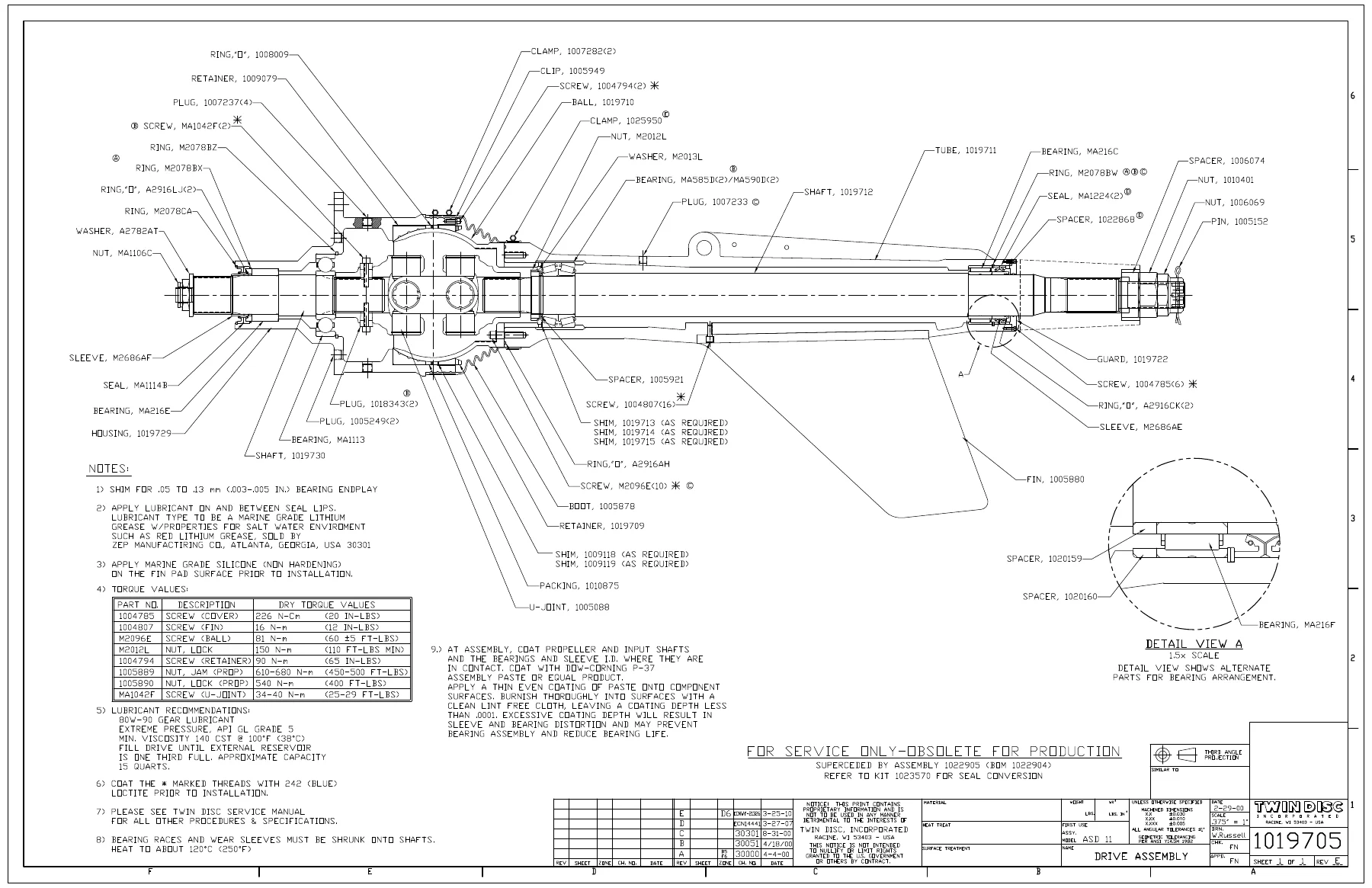
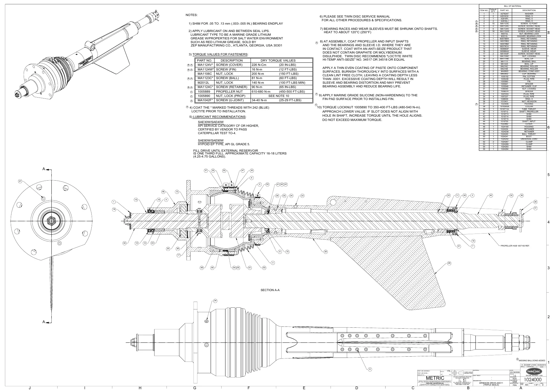
- Engineering Drawings — ASD11B1S double and triple aft-seal assembly drawings; ASD11B1L assembly drawing; SAE and metric installation drawings; Racine- and BCS-sourced steering and trim cylinders; tie bar assembly; double-to-triple aft-seal conversion diagram
Taken together, those sections give a yard or vessel technician the full path from first installation through in-service checks and a complete mechanical rebuild of the ASD11 thrust unit and its hydraulic cylinders, using the published shimming, seal, and torque data rather than guesswork.
Installation and mounting practice
The installation chapter is written for a structurally sound transom and mounting base. Optimum mounting angle is six degrees to the vessel baseline; a wedge may be required when the existing transom angle differs. Inboard and outboard transom faces must be parallel within 6.40 mm (1/4 in.), the outboard face flat within 1.60 mm (1/16 in.), and the inboard face flat within 3.18 mm (1/8 in.) in way of the socket. Clean water flow is required at least 21 cm (8 in.) each side of the propeller tips and 1.83 m (6 ft) forward of the transom. Templates 1019886B and 1020289 are used to locate the drive centerline, Point C, seven mount holes, and two lubrication holes. The through-hole is cut with a 177.8 mm (7.0 in) hole saw. The unit is mounted with a backing plate and 3/4 in. stainless bolts (M22 on BOM 1B00001), nylock nuts, and washers, torqued uniformly to 95–122 N-m (70–90 ft-lbs). The drive must stay supported until the trim cylinder is installed so the ball does not bottom in the socket.
IMAGES PREVIEW
Operation, maintenance, and troubleshooting
Before daily use, confirm drive lubrication and that the steering and trim reservoirs are filled. The lube reservoir is about one-third full when cold with the drive stopped. Under way, trim so the propeller-hub center sits at the waterline; do not trim so high that the engine exceeds its rated speed. Shift the transmission at idle. Complete overhaul is timed with engine overhaul. Daily work includes visual lube and hydraulic-level checks, propeller inspection, leak checks, and cycling the hydraulic system lock to lock. Hydraulic filter replacement and fastener / retaining-ring checks fall at the first 500 hours (not to exceed 12 months) and again at 2000 hours. Drive oil is changed as indicated by analysis. Propeller jam-nut and lock-nut torque is verified after first use or within 10 hours, then on a stepped 250 / 500 / 1000 / 1500-hour schedule until it matches the vessel haul-out interval.
The troubleshooting chart separates true drive faults from engine, transmission, and driveline problems. It covers a propeller that will not turn, trim or steering failure, noise and vibration, milky water-contaminated oil, and anode behavior that is either too fast or too slow. Remedies include driveline alignment, seal and packing replacement, bleeding the power-steering/trim system, tightening the aft retainer ring, and checking bonding resistance and galvanic isolation.
Get the procedures on the bench
With the Twin Disc Arneson Surface Drive ASD11 Service Manual ASD11B1S ASD11B1L 1022809 you can install or reinstall the thrust unit, service oil and hydraulics, protect the bronze housings from galvanic attack, diagnose leaks and vibration, remove the tube or the complete drive, rebuild shafts, bearings, U-joint, aft seals, packing, and both hydraulic cylinders, and assemble to the published shim and torque values using the listed special tools and engineering drawings. Those published clearances, lubricant specs, and fastener values are what keep seals and tapered bearings alive on a surface-piercing drive. After payment you receive the PDF immediately — no shipping wait — to open on any device and print the pages you need in the shop or on the boat.
Reviews
There are no reviews yet.