
UD Trucks GKB CWB GWB Body Installation Manual 2010 – GKB4D CWB4D GWB4D Heavy Truck Body Mounting Guide PDF
Original price was: $55.95.$34.95Current price is: $34.95.
132-page UD Trucks body installation manual for the GKB 4×2, CWB 6×4 and GWB 6×4 heavy truck series. Sub-frame design, chassis frame drilling and riveting rules, PTO and engine control wiring, electrical and air system interfaces, ADR/SSM compliance and painting precautions.
Description
UD Trucks GKB CWB GWB Body Installation Manual 2010 – GKB4D, CWB4D and GWB4D Heavy Truck Body Mounting Guide
This UD Trucks Body Installation Manual is the reference document issued in May 2010 by UD Trucks Corporation for body builders, second-stage manufacturers and modification companies working on the 4×2 GKB-Tractor, 6×4 CWB and 6×4 GWB-Tractor series of heavy-duty trucks. It lays out the basic data, dimensions and precautions required to design, manufacture and mount a quality body and general equipment onto the UD Trucks chassis-cab, and it spells out the design, mounting and modification rules that protect the chassis frame and keep the completed vehicle compliant with Australian Design Rules.
File Details
- Manual Type: Body Installation Manual (Second-Stage-of-Manufacture / Body Builder Guide)
- Brand / Publisher: UD Trucks – UD Trucks Corporation (Japan) and UD Trucks Australia (UDT)
- Covered Series: GKB 4×2 Series, CWB 6×4 Series, GWB 6×4 Series
- Covered Models: GKB4D (GKB4DADH), CWB4D (CWB4DAW), GWB4D (GWB4DLHH, GWB4DAHH); Australian sales models GK400, GW400, GW400 Long and GW470
- Language: English
- Issued Date: May 2010
- Page Count: 132
- File Format: PDF
It is worth being clear about what this document is: it is a body installation manual written for body builders and second-stage manufacturers, not a full workshop service manual. Engine overhaul, transmission repair and general service procedures are not covered here. What is covered is everything the body builder needs to interface a new body, equipment, PTO, tail-lift, crane or electrical load with a UD Trucks GKB, CWB or GWB chassis – cab without damaging the frame or invalidating compliance.
Chapters Covered
- Foreword, List of Abbreviations and Model Coding
- Vehicle Specifications
- Guidelines – Legislation
- Guidelines – Body Installation
- Chassis Frame
- Mechanical Connections Between Vehicles
- Lifting Devices
- Precautions During Electric Welding
- Precautions on Vehicles Equipped with ABS, EBS, ESCOT, AutoShift and EHS
- Relocation of Battery or Relay Box
- Precautions for Body Installation Around the AdBlue Tank
- Remodeling the Exhaust System
- Chassis Layout
- Section Modulus
- Allowance for Rear Axle, Suspension & Tyre Articulation
- PTO
- Engine Control System
- Electrical System
- Air System
- Painting
- Appendix
Vehicle Specifications
Detailed specification tables for the covered variants, including the GKB4DADH air-suspension 4×2 tractor, the CWB4DAW air-suspension 6×4 rigid with its 6500 mm wheelbase and 5500 mm minimum wheelbase warning, and the GWB4DLHH (trunnion) and GWB4DAHH (air) 6×4 tractors on a 3950 mm wheelbase. Frame material, side-rail assembly width (840 mm), tensile strength (539 MPa), yield point (471 MPa), maximum section modulus, tyre and rim sizes, and front and rear spring data are printed for each model. The GE13TB and GE13TD engine designations and the APR90A, RTLO14913A, RTLO18918B and RTLO18918A-AS3 transmission combinations are listed as fitted.
Guidelines – Legislation
The ADR compliance framework is set out for body builders: the responsibilities of the vehicle manufacturer versus the Second-Stage-of-Manufacture (SSM), the SSM and body builder ADR check list, and the ADR summary applicable to the 2008 model year. This section also references Australian Vehicle Standards Rules 1999, the Load Restraint Guide, Concessional Mass Limits, and State and Territory registration authorities, along with the specific ADR clauses that shift to the SSMM once the rear lamps and registration plate are relocated onto a new body.
Guidelines – Body Installation
This is the core of the manual. It covers sub-frame shape and mounting (the flange width rule of 70% to 100% of chassis frame flange width, the prohibition on timber sub-frames, and correct crossmember and bolster practice), front-end sub-frame shaping to avoid stress concentration, positions of front-end reinforcement, mounting brackets versus U-bolts, location plates for fore-and-aft restraint, and the connecting-device rules for the long-wheelbase truck. Full-frame drilling and riveting guidance follows, including maximum hole diameters (17 mm for GKB, CWB and GWB), edge distance rules, prohibitions on drilling flanges and crossmembers, rivet diameter and pitch values, and reinforcement-plate geometry for side member reinforcement and chassis extensions.
Precautions on Electronic Systems (ABS, EBS, ESCOT, AutoShift, EHS)
Dedicated sections explain the do-not-modify rules for the ABS, EBS, ESCOT, AutoShift and EHS (hill start assist) systems, minimum 100 mm clearance distances for radio transmitters, motors and relays, the correct electric welding shutdown sequence (ignition OFF, battery negative disconnected, ECUs isolated), and the inspection steps required after body installation. These are exactly the sections that prevent an installer from destroying an ECU or triggering a fault that puts the truck out of service.
PTO and Engine Control System
Rear engine PTO (allowable maximum output torque 441 Nm, clockwise rotation viewed from the rear) and transmission PTO specifications are given for the CWB4D and GWB4D with RTLO14913A / RTLO18918B / RTLO18918A-AS3 transmissions, and for the GKB4D with the APR90A transmission. Junction A and Junction B connection patterns, End of Line Programming (EOLP) parameters, the external engine control lever unit (Part No. 25960 ND00A), PTO and governor switch options (25165 02Z00, 25165 02Z02), and the retrofit parts list are all documented.
Electrical System
Harness layout drawings for the main harness (cab interior LH and RH), engine harness, chassis harness, tail harness and AutoShift harness, plus the location of rear combination and registration plate lamp extension harnesses and their temporary installation lengths. Additional power source terminals are detailed: the direct-to-battery terminal on the chassis harness RH (CR-14), the in-cab BAT/ACC/IGN/C source terminals in the dash cover (fuse Nos. 7, 46, 44), battery relay box power take-off, and the spare circuit wires (red and yellow, 15A) on the cab and chassis sides. General wiring precautions cover clip spacing at 300 mm, heat source clearance, and waterproofing through grommets.
Air System
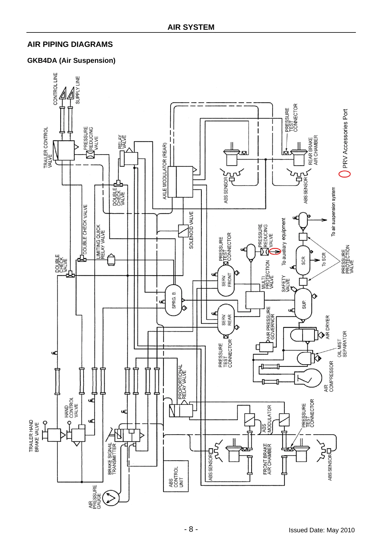
Air system practice for body builders: draining each air circuit before disconnecting anything, the preferential charging requirement of ADR 35/02 clauses 4.7.8 and 4.7.9 (all brake power units preferentially charged to not less than 450 kPa), and the requirement that air taken for air horns, PTOs, cab suspension and similar accessories must come from the delivery side of the Pressure Reducing Valve (PRV). Nylon tube handling, push-on and nut-sleeve connector service, minimum bending radii (60 mm to 150 mm by tube size), and binding-band installation with the correct tightening tool are all covered, along with air piping diagrams for the GKB4DA, CWB4DA and GWB4DL/A models.
Chassis Layout, Section Modulus and Suspension Articulation
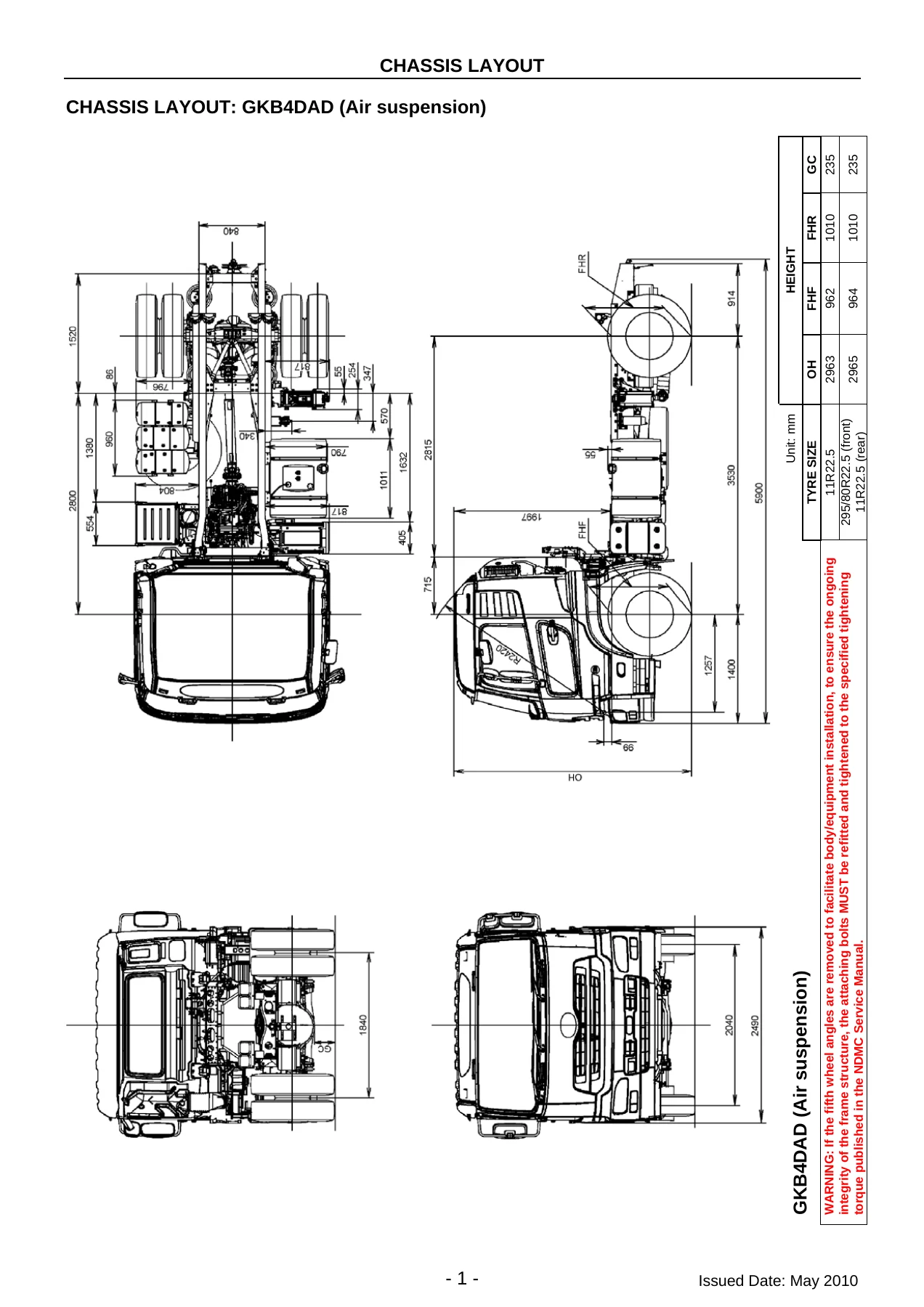
Dimensioned chassis layout drawings for the GKB4DAD (air), CWB4DAW (air), GWB4DLH (trunnion) and GWB4DAH (air) models show wheel centres, crossmember positions, frame height, cab-to-frame data and the tilt-angle geometry. Section modulus diagrams give the A-A cross-sections and the material properties of the main frame. Tyre movement, rear axle movement and articulation allowances are tabulated for the trunnion suspension and for full-floating and semi-floating air suspension, so a body builder can set body clearances correctly and allow for cab tilt and suspension travel.
Painting
Cab painting precautions include the positions of the factory black film on the cab exterior, parts that must be removed before painting, masking of parts that must not be painted, allowable temperature limits of major parts (with the 80 degrees C ceiling for forced drying and the resin and air-spring restrictions), cab painting boundaries and the disc wheel painting prohibition areas.
Appendix – Relocation Kits and Special Applications
Three service-appendix items are documented: relocation of the RHS chassis air tank on the GWB4D for spare wheel and tyre assembly fitment (UD Trucks kit Part No. 99999-ATR01), rear-of-frame air tank relocation on air-rear-suspension GWB4D models used in tipper applications (kit Part No. 99999-ATR02), and the GWB4DA rear chassis dock note for prime mover applications.
Who This UD Trucks Body Installation Manual Is For
If you are a body builder, second-stage manufacturer, modification company, fleet engineer or dealer technician involved in mounting a tray, tipper, tank, van, crane, tail-lift or fifth wheel onto a GKB4D, CWB4D or GWB4D UD Trucks chassis-cab, this is the document that governs how the job should be done. The sub-frame design rules, the chassis frame drilling and riveting limits, the welding prohibitions on the 539 MPa high-tensile frame rails, the PTO and engine control wiring patterns and the electronic system clearances are all written specifically for these trucks – not generic truck-building advice. Getting any of them wrong risks cracking a chassis rail, destroying an ECU, or causing the vehicle to fail ADR compliance at registration.
Why the Correct Procedures and Specs Matter
Heavy truck chassis frames are designed with a known bending and stress profile. Drilling a hole in the wrong place, welding across a flange, over-tightening U-bolts until the flange buckles, or welding too close to a gusset all concentrate stress and shorten the life of the frame. On the electronic side, the ABS, EBS, ESCOT, AutoShift and EHS systems are all microcomputer controlled, and a carelessly grounded welder or an unfused tap into the wrong harness can permanently damage them. This manual shows the correct allowances, clearances, torques and connection patterns so the completed vehicle behaves as intended and remains within its ADR certification.
IMAGES PREVIEW
Instant PDF Delivery of the UD Trucks GKB CWB GWB Body Installation Manual 2010
The complete 132-page UD Trucks GKB CWB GWB Body Installation Manual – 2010 is delivered as a downloadable PDF immediately after checkout. There is no shipping, no waiting for a physical book, and no risk of a missing or damaged copy. Read it on a laptop, tablet or phone at the workshop bench, print the pages you need for the job, and keep the file on hand for the next GKB, CWB or GWB body build. Whether you are checking the sub-frame flange width rule, the correct U-bolt pitch, a PTO junction connection pattern, an air tank relocation kit reference or a tyre articulation clearance, the answer is in the file and available straight away.

Reviews
There are no reviews yet.