
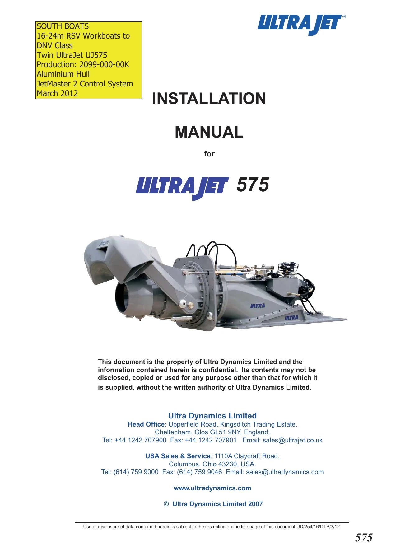
UltraJet UJ575 Waterjet Installation Manual – DNV Class Twin JetMaster 2 PDF
Original price was: $34.95.$21.95Current price is: $21.95.
Complete UltraJet UJ575 waterjet installation manual for 16-24m RSV workboats to DNV class, with Ultra JetMaster 2 control system, driveline, IQAN hardware and Humphree interceptor steering documentation bundled in a 367-page PDF.
Description
UltraJet UJ575 Waterjet Installation Manual – DNV Class Twin Installation
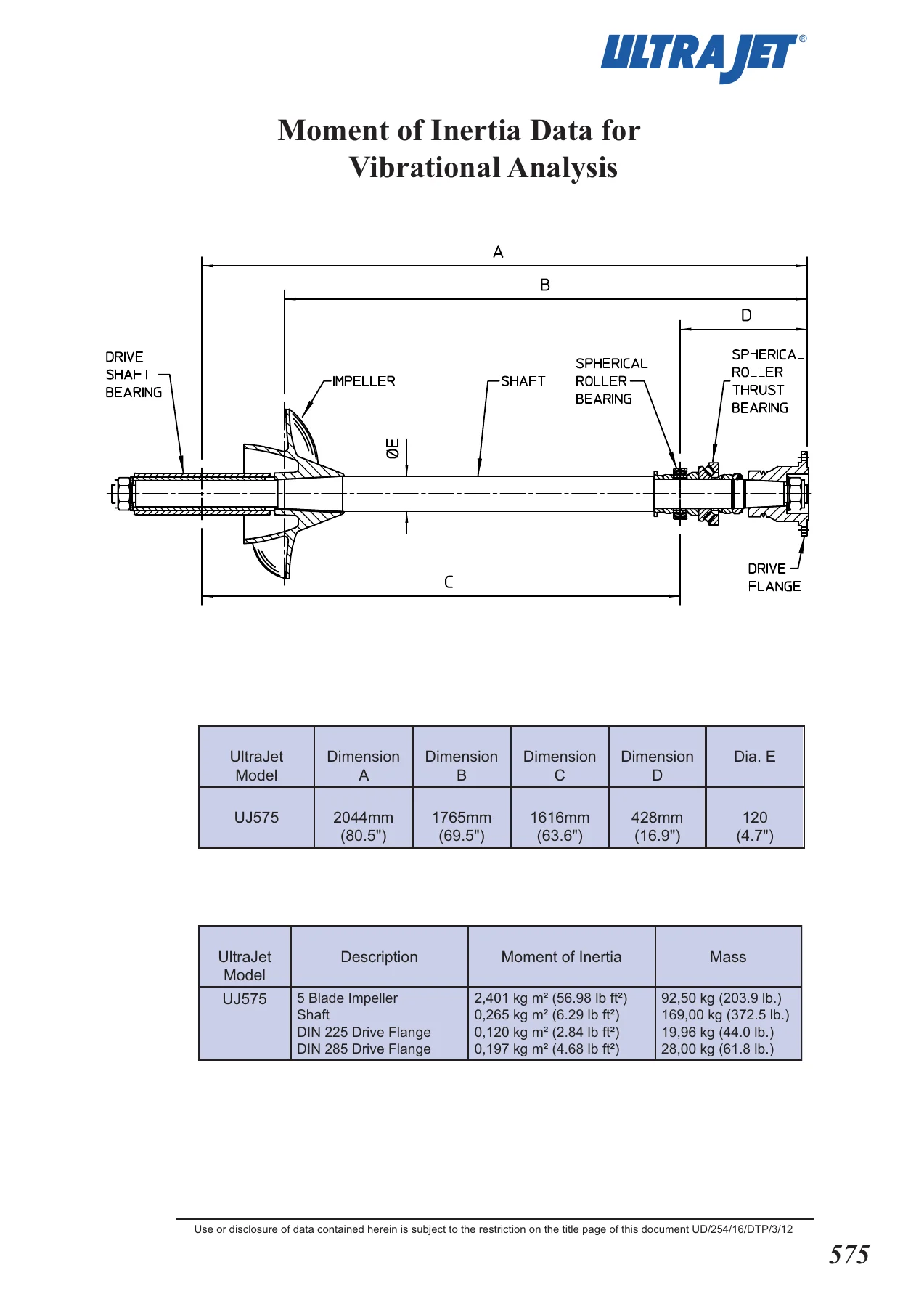
This UltraJet UJ575 Waterjet Installation Manual is the complete installation documentation set issued by Ultra Dynamics Limited for the UJ575 axial-flow waterjet fitted in twin configuration to 16-24m RSV workboats built to DNV class. The document carries production reference 2099-000-00K and is dated March 2012. It is written for boatyards, naval architects, commissioning engineers and marine technicians who need the correct torque values, sealant procedures, wiring schedules and control logic for a classed commercial installation, not for the casual owner. Alongside the UJ575 installation sections, the file bundles the Ultra JetMaster 2 control system documentation, the vessel driveline and bulkhead seal instructions, the Parker IQAN hardware manuals, the Lilaas thruster lever data, and the Humphree interceptor steering system manual that works alongside the jets on this vessel type.
File Details
- Manual type: Installation Manual (with bundled control system, driveline and interceptor documentation)
- Brand: Ultra Dynamics Limited (UltraJet)
- Model: UltraJet 575 (UJ575)
- Application: Twin UltraJet UJ575, 16-24m RSV workboats to DNV class, aluminium hull
- Language: English
- Page count: 367 pages
- File format: PDF
- Production reference: 2099-000-00K
- Issue date: March 2012
Chapters Covered
- Warranty Form
- Section 1 – General Description
- Section 2 – Specification
- Section 3 – Scope of Application
- Section 4 – Performance
- Section 5 – Installation Details (aluminium, GRP and steel hulls)
- Section 6 – Control System (Ultra JetMaster 2)
- Section 7 – Corrosion Protection
- Section 8 – Operation
- Section 9 – Fault Finding Chart
- Section 10 – Servicing & Warranty
- Section 11 – Overhaul
- Section 12 – Schedule of Parts
The UJ575 described in this UltraJet UJ575 installation manual is a single-stage axial-flow pump with a marine-grade aluminium intake section, impeller case, reaction tailpipe, nozzle and deflectors, all finished in a two-pack marine epoxy system. The impeller is stainless steel and is supplied in four or five bladed form to match the selected engine and gearbox power curve. A stainless steel liner inside the impeller case allows for replacement at service intervals. The reverse deflector is a twin-duct design that works with the steering deflector to give the low-speed manoeuvrability expected of a workboat operating around wind farm installations, oil spill response duties and harbour transfers.
Specification and performance data
Section 2 gives the dry unit weight of the UJ575 as 1,450 kg (3,196 lb), rising to 1,685 kg (3,715 lb) with entrained water. Standard nozzle diameter is 320mm (12.6 inches) with other options available. Rotation is clockwise when viewed on the input drive flange. Section 3 sets out the scope of application by hull type – displacement craft up to 596 kW (800 bhp) input, semi-displacement up to 1,082 kW (1,450 bhp) and planing craft up to 1,342 kW (1,800 bhp) – with maximum twin, triple and quad jet displacement figures for each. Section 4 provides the thrust performance curves in kN and lbs together with the power absorption curves for the range of impellers available for direct coupling to the engine flywheel, covering 1,000 to 1,700 rpm.
Installation for aluminium, GRP and steel hulls
Section 5 is the heart of this UltraJet UJ575 installation manual and handles the three hull materials separately. For aluminium hulls, the sequence covers removing the unit from packing, fitting the intake fairing and intake case onto the hull intake block with RTV silicone sealant, torquing the intake fairing nuts to 110-120 Nm (80-88 lbf.ft), drilling and tapping the transom, fitting the M12 transom studs with Loctite 270, torquing the transom flange nuts to 60-65 Nm (44-48 lbf.ft), mounting the cylinder assemblies, fitting the reverse deflector pivot pins to 410-430 Nm (302-317 lbf.ft), and filling the bearing case with the recommended oil. GRP hull installation is cross-referenced to the intake block drawings and follows the same sequence. Steel hulls use an insulating mounting frame, insulating washers, bushes and gaskets to isolate the aluminium jet from the steel structure, with a dedicated installation drawing referenced for the unit mounting.
The manual also includes the intake block interface drawing that boatyards use to build the intake block directly into the hull, with notes on cut-out dimensions, position of the transom from the edge of the intake block, and minimum cut-out detail.
Ultra JetMaster 2 control system
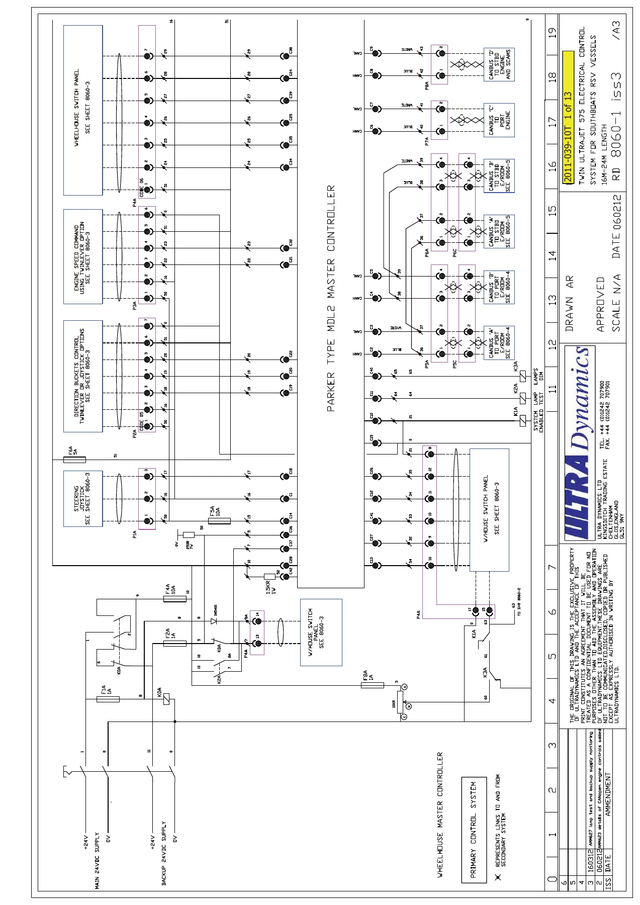
Section 6 documents the Ultra JetMaster 2 control system for twin UltraJet installations. It covers the system concept, redundancy for class (duplicated primary and secondary control systems), the Parker IQAN hardware platform, CANbus architecture and the four separate CAN channels used for jet control, engine control and ship’s SCAMS integration. The wheelhouse equipment, engine room junction boxes, hydraulic system monitoring junction box and aft peak waterjet compartment junction box are described with their connections to the electro-hydraulic proportional valves, positional feedback sensors and bearing temperature sensors. Two user control options are covered – full joystick control and combined twin-lever plus single steering joystick control – with the option to configure either as primary or secondary at build time.
The bundled JetMaster 2 screen documentation walks through every operator screen: the home screen, gearbox and clutch control screen, engine monitoring screen, main cruising screens for both control layouts, operating mode selection (harbour and four wind farm modes with defined engine idle speeds), hydraulic system monitoring, manual mode cylinder control, auto-pilot control and the interceptor steering control screen. Alarm pages, menu functions, calibration screens for feedback transducers and measured value pages are all shown, making this a complete reference for commissioning and fault-finding the control system on the vessel.
Driveline, IQAN hardware and interceptor steering
The file also bundles the Driveline Service of Portland installation and maintenance instructions for the shaft line assemblies, covering the Cardan shaft, pilot rings, watertight bulkhead seal, torque values for the marine gear and waterjet flange bolts, parallel alignment procedure within a quarter degree, and universal joint lubrication intervals. The Parker IQAN-MDL2 display module and IQAN-XA2 expansion module instruction books are reproduced in full, with I/O specifications, wiring examples for voltage, digital, frequency and directional frequency inputs, proportional and on/off output connection, addressing and termination, start-up procedures, diagnostics and environmental ratings. The Lilaas LF90 thruster control lever datasheet and the Humphree interceptor steering system installation manual and operator’s manual are also included, with mechanical installation, servo installation, control panel installation, electrical wiring, calibration and troubleshooting for the interceptor system that works with the waterjet steering on this vessel.
Operation, servicing, overhaul and fault finding
Section 7 covers corrosion protection, including the negative earth bonding system required for warranty validity, anode replacement at 50 percent volume loss and the reasons anodes must never be painted. Section 8 gives operating guidance including the rule that no power to the UltraJet means no control, slow-speed manoeuvring at around 1,000 rpm, clearing a blocked intake grill by briefly selecting reverse on the gearbox or by removing the inspection cover above the waterline, and the caution against full-throttle reverse because of cavitation damage. The fault finding chart in Section 9 matches symptoms – noisy aerated water at the nozzle, loss of thrust, excessive engine speed, water in the bearing housing oil, vibration – to possible causes and the corrective action. Section 10 covers servicing intervals, fluids, paint repair with the original PRC Desoto Titanine system, and the daily, weekly, monthly and annual checks summarised in the twin UltraJet 575 commercial operation check list. Section 11 is a full disassembly and reassembly procedure for the steering assembly, front bearing assembly and complete unit, with tool references, torque values up to 2,000 Nm for the M64 impeller nut and 1,350 Nm for the lock nut, and the sequence for fitting the mechanical seal and bearings.
Why this manual matters for a UJ575 installation
A commercial waterjet installation is unforgiving of guesswork. Get the intake fairing torque wrong, skip the RTV sealant, omit the transom flange insulating washer or leave out the earth bonding and you are looking at a failed class survey, a corroded jet and a warranty claim that will not be honoured. Get the control system wiring or the CANbus termination wrong and the vessel will not commission. The UltraJet UJ575 installation manual removes that risk by giving the actual figures, drawing numbers and procedures that Ultra Dynamics Limited specified for the UJ575, including the sections of the DNV class control system and the interceptor steering interface that are specific to this vessel type.
For a boatyard building a 16-24m RSV workboat, a naval architect confirming the intake block detail, a commissioning engineer setting up the JetMaster 2 screens and calibrating the feedback transducers, or a service technician carrying out an overhaul or diagnosing a thrust loss, this is the reference document that the rest of the installation depends on. It is also the source for the parts schedule when replacements are needed.
IMAGES PREVIEW
Instant PDF delivery
The UltraJet UJ575 installation manual is delivered as an instant download in PDF format. There is no shipping, no waiting for a physical book, and no risk of a lost or damaged paper copy. Open it on a laptop on the slipway, a tablet in the wheelhouse or a phone in the engine room, and print only the pages you need for the job in front of you. The file works on any device that reads PDF, so the drawings, torque tables and wiring schedules are available exactly where the work is being done.
Reviews
There are no reviews yet.