
UniCarriers A1N1 1N1 Series Forklift Service & Repair Manual PDF
Original price was: $44.95.$26.95Current price is: $26.95.
668-page UniCarriers (A)1N1 series forklift service manual covering maintenance, diagnostics, control systems, electrical systems, motors, drive unit, brakes, steering, hydraulics, mast/loading mechanisms, body/frame and options. Includes service data, adjustment values, tightening torques, diagrams and repair procedures.
Description
UniCarriers A1N1 1N1 Series Forklift Service & Repair Manual PDF
The UniCarriers A1N1 1N1 Series Forklift Service & Repair Manual PDF is a comprehensive 668-page service reference covering maintenance, inspection, adjustment, diagnosis, removal, disassembly, repair, reassembly and installation work for the UniCarriers (A)1N1 series. Dated September 2013, the manual is organized by major forklift systems and includes service data, specifications, tightening torques, diagnostic procedures, electrical information, hydraulic information, exploded views and step-by-step service instructions. Model variation information in the manual also identifies related ATLET, NISSAN FORKLIFT and TCM designations associated with the 1N1 family.
File Details
- Manual type: Service Manual
- Brand / series: UniCarriers (A)1N1 series
- Language: English
- Page count: 668 pages
- File format: PDF
- Publication date: September 2013
Model and Application Coverage
This UniCarriers A1N1 1N1 Series forklift service manual covers the 1N1 family across 3-wheel and 4-wheel configurations. The vehicle classification information distinguishes Europe/general-area and North American applications, standard and alternate wheelbases, frame arrangements, and traction-motor variations. The manual lists capacity codes from 1.25 ton through 2.0 ton and identifies model families used under ATLET, NISSAN FORKLIFT and TCM naming.
Visible model references include ET-13/15, ET-15L/18, ET-16L/18L/20L, EF-16L/18L/20L, AS1N1L13/15, A1N1L15/18, AG1N1L16/18/20, JAG1N1L16/18/20, FTB13-E1, FTB15-E1S, FTB15-E1, FTB18-E1, FTB16-E1, FTB18-E1L, FTB20-E1, FB16-E1, FB18-E1 and FB20-E1. Vehicle identification guidance explains model classification numbers, identification plates and VIN arrangements so the technician can match the truck to the applicable procedures and specifications before beginning work.
Chapters Covered
- General Information (GI)
- How to use this manual, identification information and model variation
- General precautions, jacking, towing, lifting and standard-bolt tightening torque
- Maintenance (MA)
- Lubrication chart, grease/oil capacities and maintenance schedule
- Battery, control system, motors, electrical components, drive unit, tires, brakes, steering, hydraulics and loading mechanism maintenance
- Control System (CS)
- Technical description, unit layouts, meter panel, LCD monitor, adjustment and diagnostic modes
- Controller inspection, error codes, unit adjustment, joystick/knob-position options and troubleshooting for driving, loading and power-steering systems
- Battery & Charger (BC)
- Battery specifications, trouble diagnoses, removal, installation and inspection
- Off-forklift battery charging and battery mounting
- Electrical System (EL)
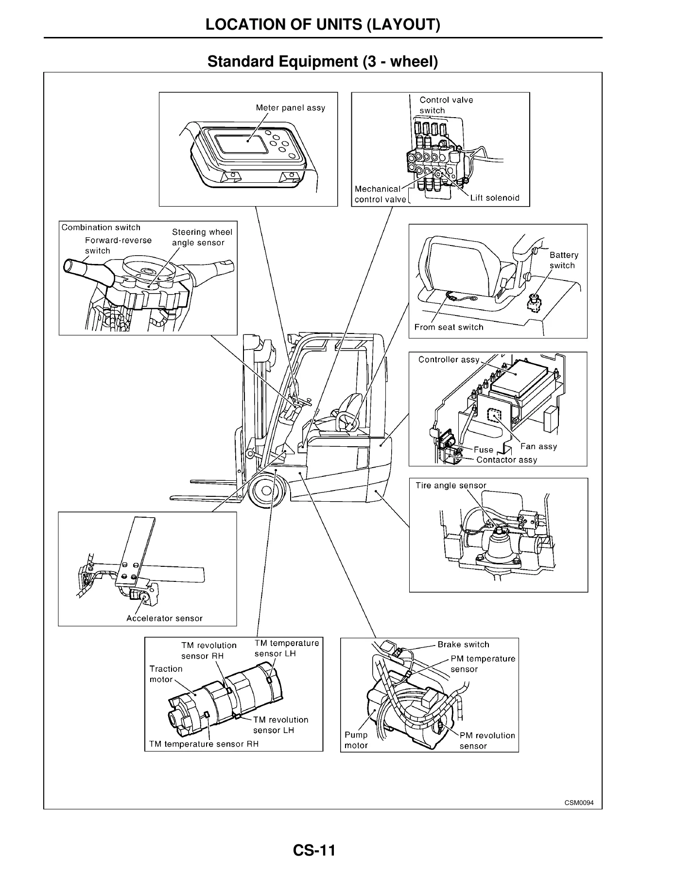
- Electrical-unit locations, harness layouts, fuses and lighting system
- Switches, miscellaneous electrical parts, battery/motor cables, optional-part locations and wiring information
- Motor Mechanism (MM)
- Service data, specifications, tightening torque and trouble diagnoses
- Traction motor, pump motor, motor removal/installation, disassembly, assembly and inspection
- Drive Unit (DU)
- General specifications, torque data, trouble diagnoses and preparation
- Reduction gear assembly, removal, installation, component parts, disassembly, assembly and inspection
- Front Tire & Rear Tire (TR)
- Tire and road-wheel specifications and tightening torque
- Trouble diagnosis, tire/road-wheel assembly, tire replacement and inspection
- Brake System (BR)
- Service data, service-brake and parking-brake diagnosis, construction and service brake
- Master cylinder, reservoir tank, brake piping, air bleeding and parking brake procedures
- Rear Axle (RA)
- Specifications, service data, construction and axle-center procedures
- Steering axle hub, kingpin, 3-wheel and 4-wheel rear-axle service and adjustment
- Steering System (ST)
- Service data, steering column assembly and power-steering valve
- Power-steering cylinders, troubleshooting, inspection, maintenance and piping
- Hydraulic System (HD)
- Service data, hydraulic circuit information, troubleshooting, inspection and adjustment
- Oil pump, tilt cylinder, lift cylinder, full-free cylinder and associated hydraulic service procedures
- Loading Mechanism (LM)
- Fork and lift-chain removal, installation, adjustment and inspection
- Carriage assembly and mast removal, disassembly, inspection, assembly, installation and adjustment
- Body & Frame (BF)
- Body/frame service data, torque specifications and precautions
- Instrument covers, floor board and mat, overhead guard, rearview mirror, seat, top panel, panels and counterweight
- Option (OP)
- Cabin front-window, door and rear-window assemblies
- Cabin electrical-component locations, outline and cabin harness layout
Taken as a whole, the manual moves from identification and routine maintenance into system-level testing, adjustment and component overhaul. It gives technicians the reference points needed to inspect faults methodically, compare measured values with service data, follow tightening requirements, locate electrical and control components, and work through mechanical and hydraulic assemblies in the sequence shown by the manual.
Diagnostics, Electrical and Control-System Work
A substantial portion of the UniCarriers A1N1 1N1 Series Forklift Service & Repair Manual PDF is devoted to control-system diagnosis. The 1N1 and A1N1 control-system material explains the LCD monitor, normal adjustment functions, diagnostic modes, controller construction, terminal layouts, sensor checks and error-code tables. The manual provides self-diagnosis and interactive-diagnosis methods, then links those checks to troubleshooting flows for controller faults, driving problems, loading-system problems, power-steering faults and turn-signal issues.
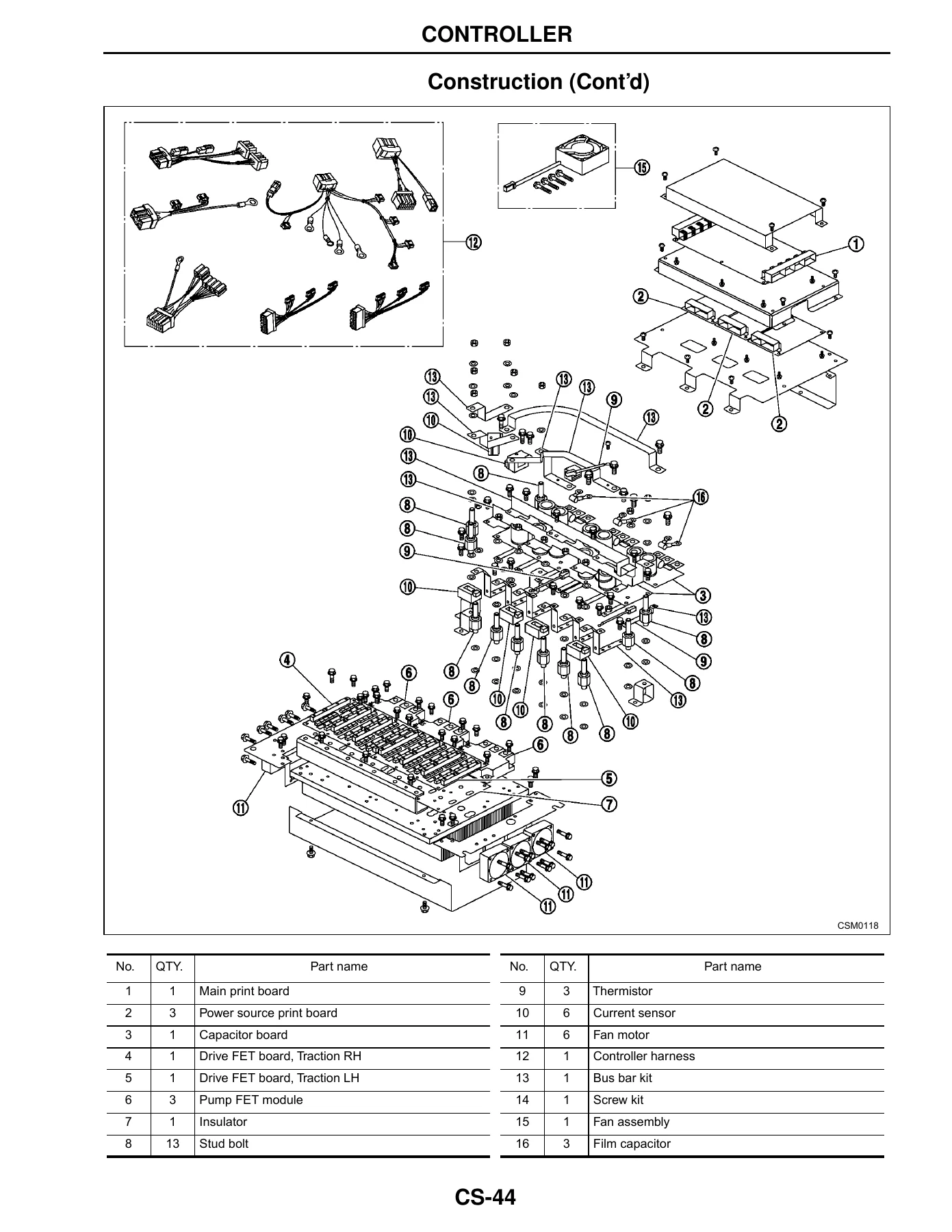
The control information is supported by connector layouts, reference voltages and resistance checks, component illustrations and system diagrams. Examples include accelerator and tire-angle sensor adjustment, steering-wheel angle sensor data, brake-switch adjustment, control-valve switches, lift solenoid checks, joystick controls, contactor and FET inspection, motor temperature and revolution sensors, controller reference data and wiring-related fault tracing. This makes the A1N1 / 1N1 forklift repair manual useful not only for component replacement but also for narrowing down electrical or electronic faults before parts are changed.
Hydraulic, Brake, Mast and Mechanical Service
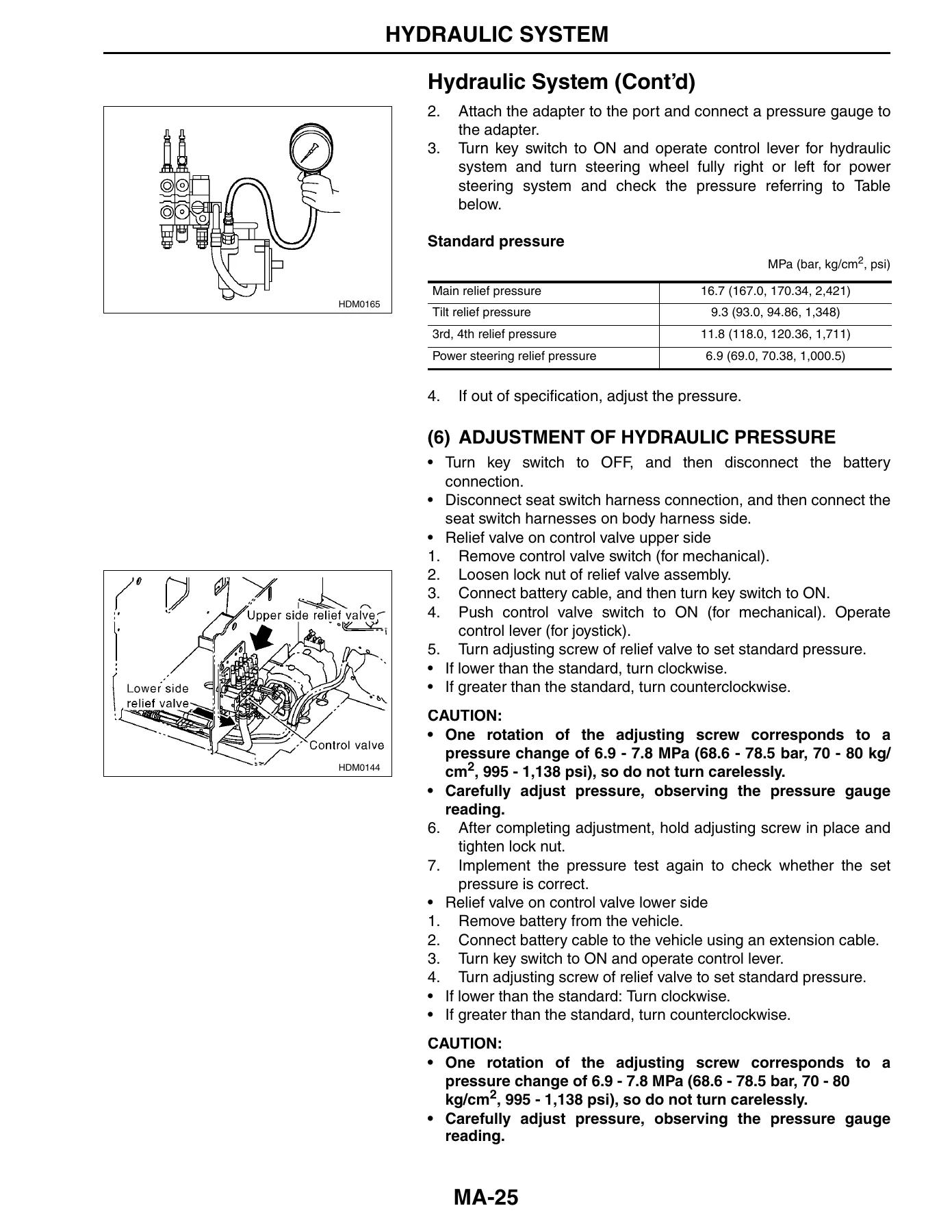
The hydraulic and loading sections provide both service procedures and measured service values. Hydraulic-fluid inspection and replacement, filter service, pressure testing and relief-pressure adjustment are covered, with standard pressures identified for the main, tilt, 3rd/4th and power-steering circuits. The loading-mechanism material covers fork inspection, carriage height, lift-chain tension, carriage and mast rollers, mast clearances, mast-cylinder and tilt-cylinder checks, lubrication points and mast configurations.
Brake coverage includes fluid inspection and replacement, bleeding, brake-disk oil, pedal inspection and adjustment, master-cylinder work, piping and parking-brake service. The drive-unit and motor chapters extend the manual into reduction-gear, traction-motor and pump-motor removal, inspection, disassembly and reassembly. Tire and wheel data, rear-axle service, steering components and body/frame work round out the mechanical coverage, including tightening torques and illustrated component locations.
Maintenance Data and Service References
The maintenance section provides lubrication charts, grease and oil capacities, inspection schedules and routine checks across the drive, electrical, brake, steering, hydraulic, mast and body systems. The first scheduled maintenance is identified at 1 month or 200 hours, whichever comes first, with periodic servicing then organized by months or operating hours. The manual also gives fluid types and capacities for 1N1 and A1N1 configurations, plus service limits, adjustment values and tightening torques throughout the relevant chapters.
Illustrated exploded views are used to show part names, tightening points, lubrication points, replacement symbols and adjustment references. Special service tools are identified where the procedure calls for them. This combination of diagrams, service data and ordered procedures helps keep repairs tied to the values and assembly sequence specified in the manual rather than relying on memory or approximate settings.
Get the UniCarriers A1N1 / 1N1 Service Manual Instantly
Use this UniCarriers A1N1 1N1 Series Forklift Service & Repair Manual PDF when carrying out scheduled maintenance, electrical and control-system diagnosis, hydraulic testing and adjustment, brake work, steering repairs, motor and drive-unit service, mast and carriage inspection, or component removal and reassembly. Having the correct procedures, service data, adjustment values, torque references, diagrams and fault-finding information in one manual helps you work systematically and verify each stage of the repair against the documented specifications.
Your purchase is delivered as an instant PDF download after payment. There is no physical book and no shipping delay. Open the manual on a computer, tablet or phone, keep it available in the workshop, and print the pages you need for a particular maintenance or repair job.
Reviews
There are no reviews yet.