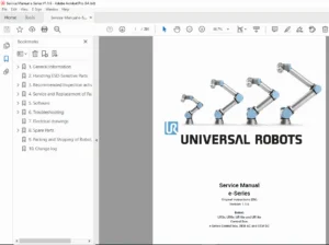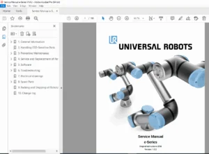
Universal Robots e-Series Service Manual PDF – DOWNLOAD
Original price was: $65.00.$15.95Current price is: $15.95.
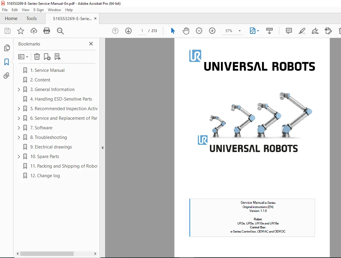
Official Universal Robots service manual for e-Series collaborative robots including UR3e, UR5e, UR10e, and UR16e models with e-Series Control Box (standard, OEM AC, and OEM DC). This comprehensive 213-page technical manual (Version 1.1.8, September 2020) covers inspection procedures, preventive maintenance, joint replacement, control box service, teach pendant repair, calibration procedures, zeroing protocols, and troubleshooting for qualified service technicians maintaining UR cobots in industrial automation applications.
Description
Universal Robots e-Series Service Manual UR3e UR5e UR10e UR16e Cobot Repair – PDF DOWNLOAD
DESCRIPTION
This is the official Universal Robots e-Series Service Manual (Version 1.1.8, September 2020) covering all e-Series collaborative robot models: UR3e, UR5e, UR10e, and UR16e, along with e-Series Control Box configurations (standard, OEM AC, and OEM DC). This comprehensive 213-page technical manual provides complete service information for qualified technicians and service personnel to inspect, maintain, troubleshoot, calibrate, and repair Universal Robots collaborative robots (cobots) used in manufacturing automation, assembly operations, and industrial applications worldwide.
Product Overview
Universal Robots e-Series Collaborative Robots:
The e-Series represents Universal Robots’ advanced line of collaborative robots designed for safe human-robot interaction in industrial environments. These cobots feature enhanced precision, built-in force/torque sensing, improved safety features, and intuitive programming for flexible automation applications. The e-Series includes four payload capacity models to suit various automation needs.
Key Applications:
- Manufacturing automation
- Machine tending
- Pick and place operations
- Assembly automation
- Packaging and palletizing
- Quality inspection
- Screw driving
- Gluing and dispensing
- Welding automation
- Material handling
- CNC machine loading
- Laboratory automation
- Testing and inspection
- Collaborative assembly
Models Covered
e-Series Robot Arms:
UR3e:
- Payload: 3 kg (6.6 lbs)
- Reach: 500 mm (19.7 inches)
- Compact tabletop model
- Precision assembly applications
- Small parts handling
UR5e:
- Payload: 5 kg (11 lbs)
- Reach: 850 mm (33.5 inches)
- Most versatile model
- General purpose automation
- Mid-range applications
UR10e:
- Payload: 10 kg (22 lbs)
- Reach: 1300 mm (51.2 inches)
- Heavy payload handling
- Palletizing applications
- Large workspace
UR16e:
- Payload: 16 kg (35.3 lbs)
- Reach: 900 mm (35.4 inches)
- Heaviest payload capacity
- Heavy part handling
- High torque applications
Control Box Models:
- e-Series Control Box (Standard)
- OEM AC Control Box (AC power input)
- OEM DC Control Box (DC power input)
Key Features and Technologies
Collaborative Robot Features:
- Force/torque sensing (all six joints)
- 17 safety functions
- Hand-guiding capability
- Protective stop functionality
- Safety-rated monitored stop
- Speed and separation monitoring
- Power and force limiting
- Tool flange I/O
- ISO/TS 15066 compliant
e-Series Enhancements:
- Improved repeatability (±0.03 mm)
- Enhanced joint encoders
- Better cable management
- Built-in force control
- Improved safety features
- Faster communication
- Enhanced durability
- Simplified maintenance
Control System:
- e-Series Control Box
- Teach pendant with touchscreen
- PolyScope graphical programming
- URCaps software platform
- Network connectivity
- Remote monitoring
- Safety controller
- I/O expansion
Technical Specifications
Robot Arm Specifications:
- 6 rotary joints (6 degrees of freedom)
- Repeatability: ±0.03 mm (UR3e/UR5e), ±0.05 mm (UR10e/UR16e)
- IP rating: IP54
- Operating temperature: 0-50°C
- Joint speed ranges
- Collision detection
- Tool communication interface
Control Box:
- Power requirements (model-specific)
- Communication interfaces
- Safety I/O
- Digital I/O
- Analog I/O
- Ethernet connectivity
- USB ports
- Power supply specifications
Teach Pendant:
- Touchscreen display
- 3-position enabling device
- Emergency stop
- Program control
- USB port
- Wrist-mounted or handheld
Comprehensive Manual Contents
DOCUMENT INFORMATION:
- Title: Service Manual e-Series
- Version: 1.1.8
- Author: UR (Universal Robots)
- Producer: madbuild
- Creation Date: September 29, 2020
- Pages: 213 pages
- Copyright: © 2009-2020 Universal Robots A/S
- Language: English (Original Instructions)
COMPLETE TABLE OF CONTENTS
SECTION 1: SERVICE MANUAL (Page 1)
- Document information
- Copyright notice
- Universal Robots trademark
- Revision information
SECTION 2: CONTENT (Pages 2-3)
- Complete table of contents
- Section navigation
- Page references
SECTION 3: GENERAL INFORMATION (Pages 1-2)
3.1 Purpose:
- Manual objectives
- Target audience
- Scope of coverage
- Service requirements
3.2 Company Details:
- Universal Robots A/S
- Contact information
- Support resources
- Regional offices
3.3 Disclaimer:
- Liability limitations
- Property rights
- Reproduction restrictions
- Change notices
- Commitment limitations
3.4 Safety Message Types:
- DANGER – Indicates imminent hazard
- WARNING – Indicates potential hazard
- CAUTION – Indicates possible damage
- NOTE – Important information
- Symbol definitions
- Safety signal words
SECTION 4: HANDLING ESD-SENSITIVE PARTS (Page 3)
Electrostatic Discharge Protection:
- ESD hazards to electronic components
- ESD-sensitive component identification
- Grounding requirements
- ESD Protection Methods:
- Conductive wrist straps
- ESD mats
- Grounded work surfaces
- Static-dissipative packaging
- Component handling procedures
- Storage requirements
- Testing and verification
- ESD awareness training
SECTION 5: RECOMMENDED INSPECTION ACTIVITIES (Pages 5-12)
5.1 Robot Arm Inspection:
5.1.1 Inspection Plan (Page 5):
- Inspection frequency
- Scheduled maintenance intervals
- Operating hour-based inspection
- Usage-dependent schedules
- Inspection checklists
5.1.2 Visual Inspection (Page 5):
- External condition assessment
- Cable condition inspection
- Connector inspection
- Joint seal integrity
- Physical damage detection
- Wear indicators
- Contamination check
- Label legibility
5.1.3 Functional Inspection (Page 6):
- Power-up sequence verification
- Joint movement testing
- All six joints operational check
- Range of motion verification
- Smooth operation assessment
- Abnormal noise detection
- Vibration check
- Temperature monitoring
- Safety function testing
- Emergency stop verification
- Protective stop testing
- Force limit verification
5.1.4 Cleaning Your Robot (Page 7):
- Approved cleaning agents
- Cleaning procedures
- Surface cleaning
- Connector cleaning
- Joint cleaning
- Cable maintenance
- Protective coating
- Contamination removal
5.2 Control Box and Teach Pendant (Pages 7-12):
5.2.1 Inspection Plan (Page 7):
- Control box inspection schedule
- Teach pendant inspection
- Cable inspection frequency
- Connector maintenance
5.2.2 Functional and Safety Inspection (Pages 8-11):
- Power-up testing
- Display functionality
- User interface testing
- Communication verification
- Safety circuit testing
- Emergency stop testing
- Enabling device testing
- I/O functionality
- Network connectivity
- Teach pendant buttons
- Touchscreen calibration
- LED indicators
- Safety system verification
5.2.3 Visual Inspection (Page 11):
- Control box exterior
- Ventilation inspection
- Cable condition
- Connector integrity
- Teach pendant condition
- Screen inspection
- Housing integrity
5.2.4 Cleaning (Page 12):
- Control box cleaning
- Teach pendant cleaning
- Screen cleaning
- Connector maintenance
- Ventilation cleaning
SECTION 6: SERVICE AND REPLACEMENT OF PARTS (Pages 13-51)
6.1 Pre-Use Assessment (Page 13):
6.1.1 Recommended Tools (Page 13):
- Torque wrenches (specific values)
- Hex keys (metric sizes)
- Screwdrivers
- Multimeter
- Cable strippers
- Crimping tools
- ESD equipment
- Lifting equipment
- Measurement tools
6.2 Robot Arm Service (Pages 14-36):
6.2.1 Movement Without Drive Power (Page 15):
- Gravity mode operation
- Manual joint movement
- Safety precautions
- Brake release procedures
- Movement limitations
6.2.2 General Guidance to Separate Joint from Counterpart (Page 16):
- Joint separation procedures
- Connection identification
- Disconnection sequence
- Cable management
- Connector protection
6.2.3 Joint Connection Types (Page 17):
- Screw Connection – Traditional bolt mounting
- Bracket Connection – Quick-release bracket system
- Connection identification
- Application of each type
6.2.4 Torque Values (Page 18): Complete torque specifications:
- Joint mounting bolts
- Tool flange screws
- Bracket fasteners
- Cable connectors
- Torque sequence
- Re-torque requirements
6.2.5 Power and Communication Connector Types on Joint (Page 18):
- Main power connector
- Communication connector
- Tool connector
- Sensor connectors
- Pinout diagrams
- Connector specifications
6.2.6 Connector Location on Joints (Page 19): Detailed diagrams showing:
- Base joint connectors
- Shoulder joint connectors
- Elbow joint connectors
- Wrist 1 joint connectors
- Wrist 2 joint connectors
- Wrist 3 joint connectors
- Access procedures
6.2.7 Screw Connection (Pages 22-24):
- Screw connection disassembly
- Joint separation procedures
- Cable disconnection
- Bolt removal sequence
- Reassembly procedures
- Torque application
- Verification testing
6.2.8 Bracket Connection (Pages 25-28):
- Bracket connection system overview
- Release mechanism operation
- Disconnection procedures
- Joint separation
- Installation procedures
- Alignment procedures
- Locking verification
6.2.9 Tool Flange (Page 29):
- Tool flange specifications
- Mounting pattern (ISO 9409-1-50-4-M6)
- Electrical connections
- Tool communication
- Payload configuration
- Center of gravity setup
- Tool installation
6.2.10 Joint Verification (Pages 30-31):
- Post-replacement testing
- Movement verification
- Encoder verification
- Communication testing
- Current consumption
- Temperature monitoring
- Safety function verification
6.2.11 Zeroing of Joints (Pages 32-34):
- Joint zeroing requirement
- Zeroing procedure
- Calibration pin usage
- Reference position
- Software procedure
- Zeroing verification
- Accuracy confirmation
6.2.12 Dual Robot Calibration (Page 35):
- Dual robot setup
- Synchronized calibration
- Coordinate system alignment
- Verification procedures
6.2.13 Program Correction by Key Waypoints (Page 35):
- Waypoint correction after service
- Path adjustment
- Position compensation
- Program update procedures
6.3 Robot Cable (Pages 36-37):
6.3.1 Replacing Robot Cable (Page 37):
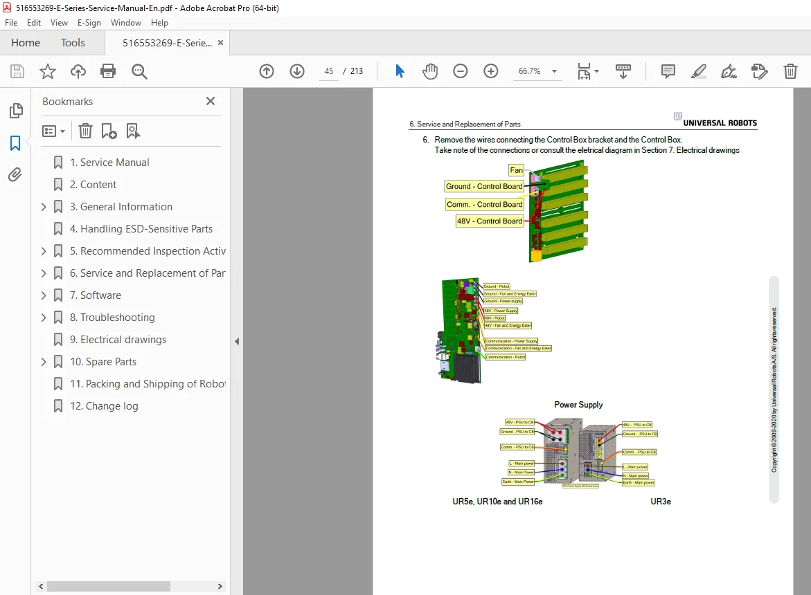
- Cable removal procedures
- Routing guidelines
- Cable protection
- Connector installation
- Cable management
- Strain relief
- Testing procedures
6.4 Control Box Service (Pages 37-51):
6.4.1 Dismantling the Control Box (Pages 37-41):
- Safety precautions
- Power disconnection
- Cover removal
- Component access
- Internal layout
- Board locations
- Cable routing
- Component identification
6.4.2 Dismantling OEM AC and DC Control Box (Page 42):
- OEM variant differences
- AC power module
- DC power module
- Special considerations
- Component access
6.4.3 Assembling Control Box (Pages 42-49):
- Component installation
- Cable routing
- Connector assembly
- Cover installation
- Seal verification
- Torque specifications
- Final inspection
6.4.4 Replacement of Teach Pendant (Page 50):
- Teach pendant removal
- Cable disconnection
- New pendant installation
- Configuration transfer
- Function testing
- Calibration verification
6.4.5 Replacement of Extension Cable (Page 51):
- Extension cable types
- Removal procedures
- Installation procedures
- Cable routing
- Connector protection
- Testing and verification
ADDITIONAL SECTIONS (Based on typical UR service manual structure)
SECTION 7: TROUBLESHOOTING
- Diagnostic procedures
- Error messages
- LED indicator meanings
- Fault isolation
- Component testing
- System diagnostics
SECTION 8: TECHNICAL SPECIFICATIONS
- Complete robot specifications
- Control box specifications
- Environmental specifications
- Safety ratings
- Performance data
SECTION 9: SAFETY INFORMATION
- Safety standards compliance
- ISO 10218-1 and 10218-2
- ISO/TS 15066 collaborative robots
- Risk assessment
- Safety configuration
SECTION 10: SPARE PARTS
- Parts catalog
- Part numbers
- Ordering information
- Recommended spares
Who Needs This Manual?
This Universal Robots e-Series service manual is essential for:
- Universal Robots certified service technicians
- Industrial automation service companies
- Manufacturing facility maintenance teams
- Robotics integrators
- OEM partners
- End-user technical staff (authorized)
- Anyone performing authorized service on UR e-Series cobots
Prerequisites:
✓ Universal Robots service training certification
✓ Collaborative robot safety training
✓ ISO 10218 and ISO/TS 15066 knowledge
✓ Mechanical and electrical troubleshooting skills
✓ Understanding of industrial robot systems
✓ ESD handling procedures
✓ Risk assessment capability
✓ PolyScope software familiarity
FILE DETAILS
| Detail | Specification |
|---|---|
| Manual Title | Service Manual e-Series – Original Instructions (EN) |
| Version | 1.1.8 |
| Robot Models | UR3e, UR5e, UR10e, UR16e |
| Control Box | e-Series Control Box, OEM AC, OEM DC |
| Author | UR (Universal Robots) |
| Producer | madbuild |
| Creation Date | September 29, 2020 |
| Manufacturer | Universal Robots A/S, Denmark |
| Pages | 213 pages |
| PDF Quality | Professional technical manual with detailed diagrams |
| File Size | 21.4 MB |
| Page Size | A4 (595.28 x 841.89 pts) |
| Language | English |
| Copyright | © 2009-2020 Universal Robots A/S |
| PDF Version | 1.4 |