
Valmet IQ Scanner Technical Manual DC113596-02 – WW1500 to WW10500 Scanner Service PDF
Original price was: $29.95.$17.95Current price is: $17.95.
Valmet IQ Scanner Technical Manual DC113596-02 covering WW1500-WW10500 scanners: mechanical structure, electrics, pneumatics, cooling circuit, start-up, alignment, periodic maintenance and component repair.
Description
Valmet IQ Scanner Technical Manual DC113596-02 – Full Hardware and Service Reference
The Valmet IQ Scanner Technical Manual DC113596-02 is the technical reference for the Valmet IQ Scanner measuring frame, the free-standing beam structure that traverses sensor platforms on both sides of the paper web and keeps them aligned for on-line measurement. It is written for Valmet and authorized service personnel who install, align, maintain and repair the scanner, and it documents the machine from the mounting feet and rails up through the drive train, shrouds, cable tracks, electric cabinets, instrument air network and sensor cooling circuit.
Coverage in this Valmet IQ Scanner technical manual spans the complete width range of the product family, from the Valmet IQ Scanner WW1500 through the Valmet IQ Scanner WW10500. It is not a condensed overview: it carries the chapter-level detail a technician needs at the machine, including the removal and refitting sequences for shrouds and carriages, alignment of the sensor platforms, calibration of the position encoder, settings for the web edge detectors and the drive inverter parameter tables in the appendix.
File Details
- Manual type: Technical manual (hardware and software description, installation, maintenance and repair)
- Brand: Valmet
- Equipment covered: Valmet IQ Scanner WW1500 to WW10500
- Document number: DC113596-02
- Revision status: Second revision – first revision 31.10.2016, second revision 15.8.2017 (typical air consumptions)
- Date: August 2017
- Language: English
- Page count: 136 pages
- File format: PDF
Chapters Covered in This Valmet IQ Scanner Technical Manual
- 1 Safety – supply voltage and frequency checks, protective covers, hot air from air heaters, rotating support rolls, locked end doors, moving platform crushing hazards, personal safety gear
- 2 Introduction – product numbers for every scanner width, general description of the measuring frame
- 3 Mechanical Structure – scanner frame, shroud and sealing belt, scanner purge air, drive shaft/clutch/gear motor, tending wheel assembly, drive belt and timing belt, platforms, cable tracks, carriage, electric equipment, platform controller, main cross connection board, pneumatic system and instrument air network, purge air equipment and air dryer, sensor cooling equipment, scanner options
- 4 Transportation
- 5 Storage
- 6 Start-up Procedures – mounting the measuring beam, alignment of platforms, power supply/grounding/optic cable connection, pneumatic connections, external water supply connection, scanner purge air connection, settings of web edge detectors, settings of motor drive parameters, calibration of position encoder, settings of the supporting rolls, settings of the support bars, installing the guide rail stopper
- 7 Periodic Maintenance – drive shaft and gear motor, clutch of drive shaft, timing belt pulleys, platforms and rolls, bearings of the platform, cable track/hoses/cables, electric equipment, instrument air equipment, purge air equipment, cooling equipment
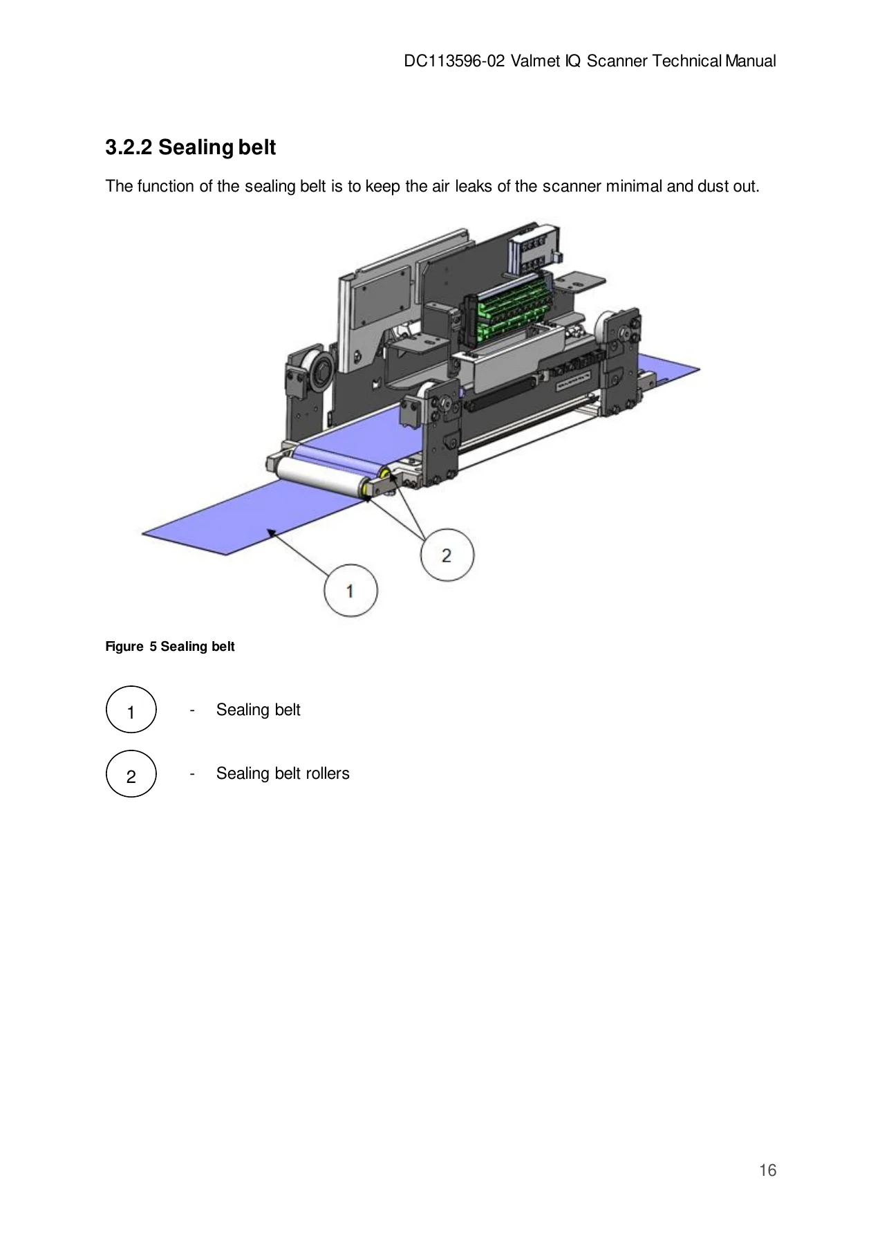
- 8 Repair of the Components – gear motor and drive belt, lower drive shaft assembly, upper drive shaft assembly, tending wheel assembly, timing belt (changing and adjusting), carriages (sealing belt rollers, rail wiper, guide rollers), replacing the sealing belt, pneumatic equipment (purge air equipment, replacing filter elements), cooling equipment, electric equipment (position encoder, drive motor’s drive, coolant pump motor’s drive), replacing the cable track
- 9 Appendix – drive inverter modified parameters, cooling system inverter modified parameters, pressure switch, main switch locking
IMAGES PREVIEW
What This Valmet IQ Scanner Service Manual Gives a Technician
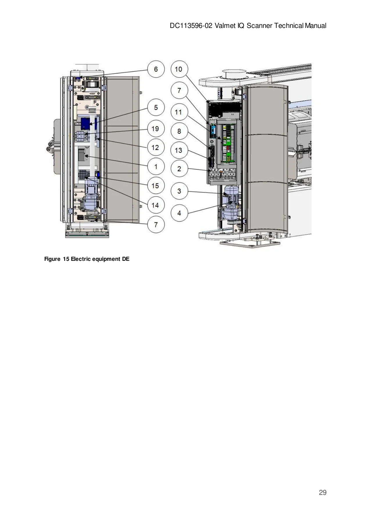
The value of the Valmet IQ Scanner Technical Manual DC113596-02 lies in how tightly it ties the scanner’s subsystems together. The mechanical chapter explains not only what each assembly is, but how the gear motor torque reaches the timing belts through the drive belt and drive shaft so that the upper and lower platforms move simultaneously, how the clutch lets the upper platform be released for service, and how the position encoder at the bottom of the drive shaft supplies platform position information. The electric chapter maps the drive-end cabinet component by component, from the motor drive and circuit breakers through the power supplies, magnetic valve of the clutch, ethernet switches, MIU assembly and industrial PC, and then lists what sits on the carriages themselves.
Because the platform controller chapter names the functions the controller actually performs – gear motor control through the motor drive, position measurement, edge detector monitoring, beam temperature measurement, control button and indicator light handling, cooling water tank level monitoring, clutch control, platform alignment switch state, purge air control, sensor cooling water temperature control and sensor bus communication – the manual doubles as a fault-finding map. When a symptom appears, the technician can work back to the I/O card or the assembly responsible rather than guessing.
The appendix tables are part of the same logic. The drive inverter modified parameters and the cooling system inverter modified parameters are listed with setting values, units and default settings, and the pressure switch appendix explains the display, output indicators, key functions and recommended purge air settings of 15 kPa with limits of plus or minus 5 kPa. Anyone replacing a drive or a cooling system inverter needs exactly this information to restore the machine to its as-delivered behaviour.
Start-Up, Alignment and Calibration Content
The start-up chapter is the part most often needed on site. It walks through mounting the measuring beam on its feet, checking foot alignment and elevation, and confirming that the bridge bearing is installed at the tend end so the beam can slide as it expands. From there it covers height adjustment, securing with lock nuts, removal of the transportation supports before alignment, use of a plumb line to bring the beam vertical, and connection of the external supplies: pressurized air, electricity, cooling air, and external water circulation. Filling the cooling water tank with 14 litres of water plus 0.07 litres of inhibitor, checking that the platform shut-off valves are closed and the venting valve is open, then closing the vent after roughly five minutes of pump running, is spelled out step by step.
Platform alignment is treated separately, with the measurement gap checked from all four corners of the platforms using Allen keys or precisely machined metal pieces, adjustment by set screws, and MD-direction alignment using the long slots in the base plate. The web edge detector settings give the nominal photoelectric sensor faceplate distance, the paper sheet clearance, the Teach-in tuning procedure and the meaning of the green and yellow LEDs. Position encoder calibration is described both for moving the encoder’s rotation point out of the scanning area and for converting pulses to millimetres using the Pos 1 and Pos 2 reference points.
Periodic Maintenance and Repair Depth
Maintenance in this Valmet IQ Scanner technical manual is organised as a schedule rather than a list of tasks. It covers running the platform to home position and locking out the safety switch before opening the scanner, cleaning sensors, checking rail wipers and rollers, inspecting cable tracks and hoses, checking filters, the water circulation, the drive belt and the timing belt, and checking bearing locking screws. At six-month intervals the schedule adds replacement of the porous plastic in the moisture indicator, rail wiper replacement, greasing of carriage bearing rollers and drive device bearings, inspection of the separation clutch, and checking the sealing belt rollers and timing belt pulleys. At yearly intervals it adds filter element replacement, drive shaft bearing lubrication, timing belt change and adjustment, and cooling water replacement with inhibitor added and the tank washed.
The repair chapter is written as procedure, not theory. Replacing the gear motor and drive belt, the lower and upper drive shaft assemblies, the tending wheel assembly, the timing belt, the sealing belt rollers, rail wiper and guide rollers, the sealing belt, purge air filters, the water pump, the mud separator filters, the position encoder, the drive motor’s drive, the coolant pump motor’s drive and the cable track are all covered with the sequence of screws to release, the components to disconnect, the tightening order and, where the manual states them, the tightening torques.
Buy This Valmet IQ Scanner Technical Manual DC113596-02
With this manual on hand, a maintenance team can mount and align a Valmet IQ Scanner measuring beam, bring the drive and cooling inverters back to their documented parameter sets, tune the edge detectors, calibrate the position encoder, adjust the timing belt to its correct vibration frequency, service the purge air system and replace worn carriage and sealing belt components without waiting on a description of the job from someone else. Working from the documented sequences and settings is what keeps platform alignment, measurement gap and scanner air pressure inside the tolerances the sensors depend on – and what keeps the scanner out of unplanned downtime.
Delivery is instant. The PDF is available to download immediately after payment, with no shipping and no waiting for a physical copy. Read it on a laptop, tablet or phone, print the pages you need for the job at hand, and keep the full Valmet IQ Scanner Technical Manual DC113596-02 on file as the scanner’s permanent service reference.
Reviews
There are no reviews yet.