Videojet 6210 PegasusHS Thermal Transfer Printer Service Manual PDF
Original price was: $65.00.$18.95Current price is: $18.95.
Official service manual for Videojet 6210 (PegasusHS) high-resolution thermal transfer printer manufactured by ICE (Interactive Coding Equipment). This comprehensive 133-page technical manual covers installation, configuration, maintenance, troubleshooting, and repair procedures for this industrial coding printer.
Includes CLARiTY controller operation, printhead service, cassette maintenance, wiring schematics, illustrated parts list, system diagnostics, and complete specifications for intermittent and continuous printing modes.
Description
Videojet 6210 PegasusHS Thermal Transfer Printer Service Manual PDF DOWNLOAD
DESCRIPTION
This is the official Videojet 6210 Service Manual (Part Number 361854-21, Revision AA, November 2006) for the PegasusHS thermal transfer printer, manufactured by ICE (Interactive Coding Equipment) and marketed under the Videojet brand. This comprehensive 133-page technical manual provides complete service information for this high-resolution industrial coding and marking system.
Product Overview
Videojet 6210 (PegasusHS) Thermal Transfer Printer:
The Videojet 6210 is a high-resolution thermal transfer printer designed for industrial coding and marking applications. It uses advanced thermal transfer technology with a unique electronic ribbon drive system, offering superior reliability and ease of operation compared to earlier systems.
Key Applications:
- Flexible packaging films
- Self-adhesive labels
- Horizontal Form/Fill/Seal (HFFS) machines
- Vertical Form/Fill/Seal (VFFS) machines
- Flow-wrap machines
- Bagging machines
- Self-adhesive label applicators
Printing Capabilities:
- Barcodes (1D and 2D)
- Date and batch codes
- Text and alphanumeric characters
- Graphics and logos
- High-resolution images
Technical Specifications
Printing Technology:
- Type: High-resolution thermal transfer
- Resolution: 300 dpi (12 dots/mm)
- Printhead: Miniature heating elements under glass coating
- Print Media: Thermal transfer ribbon with ink-bonded carrier
Printing Modes:
- Intermittent Mode – Prints on stationary substrate (start/stop action)
- Continuous Mode – Prints on moving substrate with speed matching
Physical Specifications:
- Configuration: Available in left-handed or right-handed versions
- Mounting: Can be mounted in any orientation
- Dimensions: Detailed dimensions provided for 30mm RH printer
- Weight: Suitable for industrial mounting applications
Power Requirements:
- Input Voltage: 90-264 VAC
- Power Consumption: 320 VA
- Frequency: 47-63 Hz
- Electrical Safety: Tested and certified for compliance
Compressed Air Requirements:
- Pressure: 87 psi (6 bar) maximum
- Quality: Dry, uncontaminated air
- Fitting: 6mm pipe fitting
- Tubing: 4mm air tubing included
Print Trigger:
- PLC signal
- 24V DC, PNP registration photocell
- 24V DC, PNP proximity switch (detecting cam timing point)
Speed Monitoring:
- Encoder kit (P/N 403358) for continuous motion applications
- Speed matching capability for moving substrates
System Components
Standard Equipment:
- Printer Unit – Main printing mechanism
- Cassette – Ribbon cassette assembly
- CLARiTY Controller – Advanced touchscreen control system
- Air Regulator – Precision air pressure control
- Power Cable – AC power connection
- I/O Low Profile Cable Assembly – Input/output connections
- CLARiTY Configuration Manager CD – Setup software
- 4mm Air Tubing – Pneumatic connections
- CLARiTY Controller Bracket – Mounting hardware
- QA Documentation – Quality assurance and CE certificate
Comprehensive Manual Contents
CHAPTER 1: SAFETY
Safety Conventions:
- Warning notices – Personal injury prevention
- Caution notices – Equipment damage prevention
- Symbol explanations
Safety Guidelines:
- Electrical code compliance
- Warning label requirements
- Proper printer placement
- Using printer accessories safely
- Equipment maintenance safety
- High-voltage precautions
- Hot surface warnings (thermal printhead)
Important Warnings: ⚠ Read safety chapter before installation/operation
⚠ Only qualified personnel should service equipment
⚠ Use only approved accessories and supplies
⚠ Follow electrical safety codes
⚠ Do not remove warning labels
CHAPTER 2: INTRODUCTION
Equipment Description:
- Intended use of the product
- Thermal transfer technology explanation
- Replacement for hot stamp or rotary printers
- Application suitability
About This Manual:
- Target audience: Trained service personnel
- Manual organization
- Related documents reference
- Supplement to formal training
Related Documentation:
- Videojet 6210 Operator Manual (P/N 361853)
- Mandatory reading before service manual
Theory of Printing:
Thermal Transfer Process:
- Printhead heating elements (300 dpi)
- Carrier ribbon with bonded ink
- Printhead pressure against ribbon
- Heat transfer of ink to substrate
- Programmable print elements
Intermittent Motion Printing:
- Stationary substrate printing
- Printhead traverses across ribbon
- Printhead presses against flat platen pad
- Applications: VFFS, bagging, label applicators
Continuous Motion Printing:
- Moving substrate printing
- Encoder-monitored speed
- Ribbon speed matching
- Printhead presses against rotating print roller
- Applications: VFFS, HFFS, flow-wrap machines
CHAPTER 3: TECHNICAL DESCRIPTION
Unpacking the Printer:
- Complete parts list verification
- Damage inspection procedures
- Contact information for missing parts
Installing the Printer:
- Service requirements checklist
- Power specifications
- Compressed air requirements
- Print signal requirements
- Encoder requirements for continuous mode
Mounting Considerations:
Printer Mounting:
- Any orientation capability
- Operator access requirements
- Physical space constraints
- Print position requirements
- Mounting hole locations
- Cable and air line clearances
CLARiTY Controller Mounting:
- Controller placement guidelines
- Bracket installation
- Cable routing
Air Regulator Installation:
- Regulator positioning
- Tubing connections
- Pressure adjustment
Encoder Installation:
- Encoder mounting (continuous mode)
- Speed monitoring setup
- Signal connections
Installing Ribbon in Cassette:
- Step-by-step cassette loading
- Ribbon threading procedures
- Proper ribbon tension
- Ribbon supply and take-up spools
Adjusting Air Pressure:
- Pressure gauge settings
- Optimal pressure for different applications
- Pressure testing procedures
Working with Printer Connections:
Product Sensors/Print Signals:
- PLC signal connections
- Photocell connections
- Proximity switch connections
- Signal specifications
Encoder Connections:
- Encoder wiring
- Signal types
- Cable specifications
Interlocks and Annunciation:
- Safety interlock connections
- Status indication outputs
- Alarm outputs
Data Communication:
- Serial communication setup
- Network connections
- Protocol specifications
Cable Connections:
- Complete wiring guide
- Connector pin assignments
- Cable routing best practices
Switching Power On:
- Initial power-up sequence
- LED indicators during startup
- System initialization
Configuring the Printer:
CLARiTY Configuration Manager:
- Software overview
- System requirements
- Installation procedures
- Connecting to printer
- Parameter editing
- Saving configurations
- Archiving parameters
- Loading saved archives
Working with Inputs and Outputs:
- Input configuration
- Output configuration
- I/O testing procedures
Default Options Configuration:
- Factory default settings
- Custom configuration options
- Configuration backup/restore
CHAPTER 4: CLARiTY OPERATING SYSTEM
Getting Started with CLARiTY:
- Touchscreen navigation
- Menu structure
- User interface overview
Using the Tools Page:
- Setup page navigation
- Diagnostics access
- System information
Working with Setup Page:
- Printer configuration parameters
- Print mode selection
- Speed settings
- Temperature settings
- Print density adjustment
- Registration settings
Working with Diagnostics:
- Comprehensive diagnostic tools
- Sensor testing
- Motor testing
- Encoder verification
- Printhead testing
- I/O testing
- Communication diagnostics
- System status monitoring
Working with Passwords:
- Password protection setup
- Access level configuration
- Security settings
- Password management
CHAPTER 5: MAINTENANCE
Maintaining the Power Supply:
- Power supply inspection
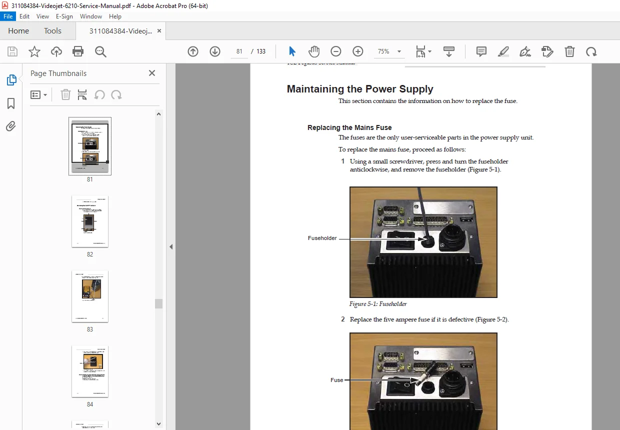
- Mains fuse replacement
- Fuse specifications
- Safety precautions
Maintaining the CLARiTY Controller:
Power Supply Unit Replacement:
- Removal procedures
- Installation procedures
- Testing procedures
CLARiTY Processor PCB and LCD Touchscreen Replacement:
- Disassembly procedures
- Component removal
- LCD touchscreen replacement
- Processor board replacement
- Cable reconnection
- Reassembly and testing
Maintaining the Printer:
Compact Flash Card Replacement:
- Card location
- Removal procedure
- Installation procedure
- Data backup/restore
Main PCB Replacement:
- Safety precautions
- PCB removal steps
- New PCB installation
- Configuration restoration
- Testing procedures
Peel Roller Replacement:
- Roller wear inspection
- Removal procedure
- New roller installation
- Alignment verification
Printhead Replacement:
- Printhead removal procedure
- Cleaning procedures
- New printhead installation
- Alignment procedures
- Testing procedures
Setting Printhead Resistance:
- Resistance measurement
- Adjustment procedures
- Optimal resistance values
- Verification testing
Maintaining the Cassette:
- Cassette inspection
- Cleaning procedures
- Ribbon guide maintenance
- Cassette component replacement
- Cassette testing
Updating CLARiTY Operating Software:
- Software update procedures
- Backup before update
- Update file loading
- Installation process
- Verification procedures
CHAPTER 6: SYSTEM EVENTS
- Event log interpretation
- Error message meanings
- Warning indicators
- System status messages
- Event history tracking
CHAPTER 7: TROUBLESHOOTING
- Systematic troubleshooting approach
- Common problems and solutions
- Print quality issues
- Paper feed problems
- Communication errors
- Sensor malfunctions
- Motor problems
- Temperature issues
- Ribbon feed problems
- Registration errors
- Diagnostic tree procedures
CHAPTER 8: ILLUSTRATED PARTS LIST (IPL)
How to Read the IPL:
- Understanding illustrations
- Alphabet callout system
- Number reference system
- Parts table interpretation
Controller Assembly:
- Exploded view diagrams
- Part numbers and descriptions
- Quantity information
Printer Assembly:
- Complete printer breakdown
- Component identification
- Assembly relationships
Printhead Assembly:
- Detailed printhead components
- Heating element specifications
- Connector details
Cassette Assembly:
- Ribbon cassette components
- Supply and take-up mechanisms
- Guide roller details
Accessories:
- Optional components
- Mounting brackets
- Encoder kits
- Cables and connectors
Printer Ribbons:
- Compatible ribbon types
- Ribbon specifications
- Part numbers
- Ordering information
CHAPTER 9: DRAWINGS
Printer Dimensions:
- Detailed dimensional drawings
- 30mm RH printer dimensions
- Mounting hole locations
- Clearance requirements
- Cable exit points
Electrical Wiring Schematics:
- Complete wiring diagrams
- Power supply schematics
- Control circuit diagrams
- I/O wiring
- Sensor connections
- Motor connections
- Communication wiring
- Grounding diagrams
Regulatory Compliance
United States:
- FCC Part 15 compliance (Class A digital device)
- TUV Rheinland certified
- Safety and emissions testing
Canada:
- Radio Interference Regulations compliance
- CSA certification
- TUV Rheinland certified
European Union:
- CE mark compliance
- EN55022:1998
- EN55024:1998
- EN61000-6-2:2001
- FCC CFR 47 Parts 15.107 and 15.109
Service and Support
ICE Service Program – Total Source Commitment:
- Applications support
- Installation services
- Maintenance training
- Customer response center
- Technical support
- Field service
- Extended hours phone assistance
- Parts and supplies
- Repair service
Customer Training:
- Recommended training courses
- Hands-on service training
- Certification programs
- Training contact: 01159 640144
Contact Information: Interactive Coding Equipment (ICE)
Olympic House, Willow Drive
Sherwood Park, Nottingham
NG15 0DP, United Kingdom
Phone: 01159 640144
Fax: 01159 639317
Who Needs This Manual?
This Videojet thermal printer technical documentation is essential for:
- Authorized ICE/Videojet service technicians
- Packaging equipment maintenance personnel
- Industrial printer repair specialists
- Manufacturing plant maintenance teams
- Technical training centers
- Anyone requiring component-level service on Videojet 6210 printers
Prerequisites:
✓ Completion of ICE/Videojet training courses (highly recommended)
✓ Understanding of thermal transfer printing technology
✓ Electrical troubleshooting skills
✓ Mechanical aptitude
✓ Reading of Operator Manual (P/N 361853) mandatory
✓ Knowledge of packaging machinery
FILE DETAILS
| Detail | Specification |
|---|---|
| Manual Name | PegasusHS Service Manual |
| Product Name | Videojet 6210 Thermal Transfer Printer |
| Manufacturer | ICE (Interactive Coding Equipment) / Clearmark Solutions LLP |
| Brand | Videojet |
| Part Number | 361854-21 |
| Revision | AA |
| Publication Date | November 2006 |
| Last Modified | February 24, 2015 |
| Author ID | 941285 |
| Pages | 133 pages |
| PDF Quality | High-quality professional manual with detailed diagrams and schematics |
| File Size | 15.9 MB |
| Page Size | A4 (595 x 842 pts) |
| Language | English |
| Copyright | 2006 Clearmark Solutions LLP (ICE) |
| Creator | FrameMaker 7.1 |