
★ TRUSTED BY 321,897+ PROFESSIONALS WORLDWIDE
🏢
Trusted Business
Verified & Licensed
🛡️
Virus Free Files
100% Safe Downloads
🔒
Secure Payment
SSL Protected
Instant Delivery
Available Immediately
Sale!

Vogele MT 3000-2 Series 0761 Spare Parts Catalogue 2021 PDF

Original price was: $29.95.Current price is: $17.95.

Joseph Vögele AG spare parts catalogue for series 0761 MT 3000-2 family machines, issued 17.05.2021. Multilingual exploded drawings and part lists covering chassis, operator stand, engine group, hydraulics, 24 V electrics, crawler drive, conveyor, cleaner, lubrication, service kits and accessories.

Instant PDF Download
Available immediately
💾
Save to Your Device
Download & keep forever
🛡️
Antivirus Scanned
100% virus-free
🌍
Trusted Worldwide
175,000+ customers

Description

Vogele MT 3000-2 Series 0761 Spare Parts Catalogue 2021 PDF

This Vogele MT 3000-2 Series 0761 Spare Parts Catalogue 2021 PDF is the Joseph Vögele AG Ersatzteilkatalog issued 17 May 2021 for series 0761 machines identified on the plates as 0761 (MT 3000-2). The document is written so a parts counter, workshop buyer or field technician can match a drawing position to a Teile-Nr. / Part No., a validity band, a quantity and a four-language designation. Drawings and lists run in German, English, Spanish and French. Publisher data printed in the catalogue is JOSEPH VÖGELE AG, Joseph-Vögele-Str. 1, 67075 Ludwigshafen, Germany.

File Details

  • Manual type: Spare parts catalogue / Ersatzteilkatalog
  • Brand / model family: Vögele MT 3000-2, series 0761
  • Languages: German, English, Spanish, French
  • Page count: 759
  • File format: PDF
  • Date of issue: 17.05.2021
  • Catalogue list part shown on the opening parts page: 2141225

Machines Named in the Drawings

The cover and group plates centre on MT 3000-2, but individual Bildtafeln also call out configuration names printed on the same series 0761 sheets. Those names include MT 3000-2, MT 3000-2 OFFSET, MT 3000-3, MT 3000-3 OFFSET, MT 3000-2i, MT 3000-2i OFFSET, MT 3000-3i and MT 3000-3i OFFSET. Engine-station plates further split some assemblies as MT 3000-2 / TIER 3, MT 3000-2 OFFSET / TIER 3, MT 3000-3 / TIER 3 and MT 3000-3 OFFSET / TIER 3. The catalogue itself warns that it contains the full possible supply scope for the machine type, so more parts may be drawn than are fitted on one particular unit. Identification is by the serial number on the type plate and chassis, not by guessing from the drawing set alone.

How the Catalogue Is Meant to Be Used

Every exploded view carries position balloons that point into the facing Ersatzteilliste. Columns on those lists are Position, Teile-Nr. / Part No., Gültig für / Valid for, Menge / Quantity, Einheit / Unit, and the four-language Benennung / Designation block. Validity bands such as 10-9999, 33-9999, 96-9999, 155-9999, 165-9999, 170-374 and 170-9999 appear throughout; they are the catalogue’s own way of tying a part number to a machine range. Cross-references on the drawings send the reader to another group number when a sub-assembly is broken out elsewhere, for example a boxed arrow to group 03.05.01 in the introductory example, or arrows on later plates to 04.01.01, 06.03.04, 08.01.02, 08.02.00, 08.04.00, 10.02.00, 10.02.15, 10.05.04, 13.01.01 and 41.30.00.

The opening pages also print the house abbreviations used on later plates: AB extending screed, SB fixed-width screed, AT extending unit, VB bolt-on extension, P pressure bar, T tamper, V vibrators, HE hydraulic bolt-on extensions, MA tightening torque, VSS wear parts. Travel or working direction is marked with an arrow on each Bildtafel. Selected fasteners carry printed MA values on the drawing itself, for example MA 16 Nm on the 24 V power-supply plate, MA 520 Nm Loctite X on the left crawler track, MA 190 Nm Loctite X on the push-roller, MA 20 Nm and MA 30 Nm on the cleaner unit, MA 0,9 Nm and MA 7 Nm on the hydraulic tank, and console values such as MA 10 ±0,5 Nm, MA 1,2 ±0,1 Nm and MA 3,5 ±0,1 Nm.

Chapters Covered

  • 01.00.00 Chassis / safety device — operating and warning labels left, right, front, rear, LRC, HRC, DEF and 230 V plates
  • 02.00.00 Operator’s stand — including operator console, electrics (group 02.02.00)
  • 04.00.00 Engine / motor group — engine station (04.01.00), diesel engine, coupling, mounts, support bracket, fan, cooler, hood parts
  • 05.00.00 Hydraulic oil feed — hydraulic tank and related filter / filler hardware
  • 06.00.00 Electrical system — 24 V power supply, batteries, cable runs and referenced wiring groups
  • 08.00.00 Advance drive — crawler track left side and linked drive groups
  • 09.00.00 Steering system — direction indicator and related hopper-side hardware
  • 10.00.00 Conveyor unit — push-roller and the long material-transport section that occupies a large share of the book
  • 13.00.00 Cleaner unit — wash / cleaner pump, tank and pipework
  • 18.00.00 Lubrication unit — grease lines, distributors and pump hardware
  • 41.00.00 Service sets — 50-hour service kit and related packaged service items
  • 42.00.00 Tools / accessories — loose accessories plus communication package / headset

Complete PDF Bookmark Tree

Complete Bookmarks

The complete bookmarks in the “Vogele MT 3000-2 Series 0761 Spare Parts Catalogue 2021 PDF” are as follows:

0761 (MT 3000-2)p. 12
LISTA DE RECAMBIOS (SN )p. 14
01.00.00 / 00 CHASIS / SISTEMAS DE SEGURIDADp. 14
– INSTRUC. MANEJO Y AVISOp. 14
– INSTRUC. MANEJO Y AVISOp. 16
– INSTRUC.MANEJO Y AVISO DELANTEp. 18
– INSTRUC.MANEJO Y AVISO ATRÁSp. 20
– INSTRUC. MANEJO Y AVISO LRCp. 22
– INSTRUC. MANEJO Y AVISO HRCp. 24
– INSTRUC.MANEJO Y AVISOp. 26
– INSTRUC. MANEJO Y AVISO DEFp. 28
– INSTRUC.MANEJO Y AVISOp. 30
– INSTRUC.MANEJO Y AVISOp. 32
– INSTRUC.MANEJO Y AVISO IZQ.USAp. 34
– INSTRUC.MANEJO Y AVISO DCHA USAp. 36
– INSTRUC.MANEJO Y AVISO DELANTEp. 38
– INSTRUC.MANEJO Y AVISO ATRÁSp. 40
– INDICACIONES DE AVISOp. 42
– SIGNOS DE MAQUINARIAp. 44
– SIGNOS DE MAQUINARIA "I"p. 46
– SIGNOS DE MAQUINARIA OFFSETp. 48
– SIGNOS DE MAQUINARIA "I" OFFSETp. 50
– KIT DE ETIQUETAJEp. 52
– KIT DE ETIQUETAJEp. 54
– KIT DE ETIQUETAJEp. 56
– KIT DE ETIQUETAJEp. 58
– REVESTIMIENTO LATERALp. 60
– RECUBRIMIENTO:ESTACION MOTOR 1p. 64
– RECUBRIMIENTO:ESTACION MOTOR 2p. 68
– RECUBRIMIENTO:ESTACION MOTOR 2p. 70
– ENCLAVAMIENTOp. 72
– DISP. DE PROTECCIÓNp. 74
– ILUMINACIÓN, HALÓGENO TECHOp. 76
– ILUMINACIÓN, XENÓN TECHOp. 78
– ILUMINACIÓN – HALÓGENAp. 80
– ILUMINACIÓN, XENÓNp. 82
– GLOBO LIGEROp. 84
– GLOBO DE LUZ CON LEDp. 86
– FIJACIÓNp. 88
– FIJACIÓNp. 90
– FIJACIÓNp. 92
– FIJACIÓNp. 94
– FARO DE TRABAJO 24Vp. 96
– LUZ OMNIDIRECCIONAL SIN TECHOp. 98
– LUZ OMNIDIRECCIONAL CON TECHOp. 100
– BOCINAp. 102
– TRANSMISOR DE NIVEL DE LLENADOp. 104
– PROTECTOR ANTICHOQUES,MECÁN.p. 108
– PROTECTOR ANTICHOQUES,MECÁN.p. 110
– PROTECTOR ANTICHOQUES,ELÉCTR.p. 112
– PROTECTOR ANTICHOQUES,ELÉCTR.p. 114
– PROTECTOR ANTICHOQUES,ELÉCTR.p. 116
– PROTECTOR ANTICHOQUES,RADIOp. 118
– ESPEJO CON FIJACIÓNp. 120
– ESCALERAp. 122
– CHASISp. 126
– CHASISp. 128
– CHASISp. 130
– ELEMENTOS DE MONTAJE: CHASSISp. 132
– ELEMENTOS DE MONTAJEp. 136
– ELEMENTOS DE MONTAJE: CHASSISp. 142
– CUBIERTA: CHASSISp. 146
– CUBIERTAp. 148
02.00.00 / 00 PUESTO DEL CONDUCTORp. 152
– PUPITRE DE MANDO:ELÉCTRICAp. 152
– PUPITRE DE MANDOp. 154
– JOYSTICKp. 156
– CARRO DEL PUPITREp. 160
– CARRO DEL PUPITREp. 164
– BARRA DESLIZ.: CADENA ENERGIAp. 168
– BARRA DESLIZ.: CADENA ENERGIAp. 170
– PLATAFORMAp. 176
– CAPERUZA SIN TECHOp. 180
– CAPERUZA PARA TECHOp. 184
– CONSOLA ASIENTO CON BARANDILLAp. 188
– CAPERUZA SIN TECHOp. 190
– ASIENTO DEL CONDUCTORp. 192
– ASIENTO DEL CONDUCTORp. 194
– ASIENTO DEL CONDUCTORp. 196
– ASIENTO DEL CONDUCTORp. 198
– CUPHOLDERp. 200
– SOPORTE DE TECHOp. 202
– TECHO PROTECTORp. 206
– FIJACIÓN, TECHO PROTECTORp. 208
– BASTIDOR DE TECHO SIN VIDRIOp. 210
– VIDRIO FRONTALp. 212
– TECHADOp. 214
– TECHADOp. 216
– RETROVISORp. 218
– RETROVISORp. 220
– CUBIERTA DE TECHOp. 222
– PARABRISAS DE PLÁSTICOp. 224
– SISTEMA CÁMARAp. 226
– KIT DE HERRAMIENTASp. 228
04.00.00 / 00 MOTOR DEL GRUPO ACCIONADORp. 230
– UNIDAD MOTRIZp. 230
– MOTOR DIESELp. 234
– UNIDAD MOTRIZp. 236
– MOTOR DIESELp. 240
– UNIDAD MOTRIZp. 242
– MOTOR DIESELp. 246
– ALIMENTACIÓN DE COMBUSTIBLEp. 248
– ALIMENTACIÓN DE COMBUSTIBLEp. 252
– SISTEMA DE ESCAPEp. 256
– SISTEMA DE ESCAPEp. 258
– SISTEMA DE ESCAPEp. 262
– ADBLUEp. 266
– AIRE COMBUSTIONp. 272
– ASPIRACIÓN DE AIREp. 274
– ASPIRACIÓN DE AIREp. 278
– SISTEMA DE REFRIGERACIÓNp. 282
– SISTEMA DE REFRIGERACIÓNp. 286
05.00.00 / 00 SISTEMA HIDRAULICOp. 290
– DEPÓSITO HIDRÁULICOp. 290
– RADIADOR ACEITE HIDRAULICOp. 292
– FILTRO DE ACEITE EN DESVÍOp. 294
– REDUCTOR DISTRIBUCIÓN BOMBAp. 296
– FUNCIONES CILINDRICOSp. 298
– BOMBA-CILINDROS HIDR. (CINTA)p. 300
– ACEITE DE FUGASp. 302
– ACCIONAMIENTO DE SINFÍN, HIDR.p. 304
– ALIMENTACIÓN ACEITE HID.-CINTAp. 306
– RADIADOR ACEITE HIDRAULICOp. 308
– MOVIMIENTO DE RETROCESOp. 310
– HID.:ALIMENTACION DE CORRIENTEp. 312
– SISTEMA HIDRÁULICOp. 314
– SISTEMA HIDRÁULICOp. 316
– SISTEMA HIDRÁULICOp. 318
– SISTEMA HIDRÁULICOp. 320
– BLOQUE DE VÁLVULAp. 322
– BLOQUE DE VÁLVULAp. 324
– BLOQUE DE VÁLVULAp. 326
– BLOQUE DE VÁLVULAp. 328
– BLOQUE DE VÁLVULAp. 330
– BLOQUE DE VÁLVULAp. 332
– BLOQUE DE VÁLVULAp. 334
– BLOQUE DE VÁLVULAp. 336
06.00.00 / 00 SISTEMA ELECTRICOp. 338
– ALIMENTACIÓN DE CORRIENTE,24 Vp. 338
– SIN ALIMENTACION DE CORRIENTEp. 342
– SIN ALIMENTACION DE CORRIENTEp. 344
– CAJA DE ENCHUFE 12Vp. 346
– CAJA DE ENCHUFE 24Vp. 348
– CAJA DE DISTRIBUCIÓN,CPL.p. 350
– CAJA DE MANDO,MECÀNICAp. 352
– CAJA DE MANDO,PLACA DE MONTAJEp. 354
– CAJA DE MANDO,MANDOp. 356
– CAJA DE MANDO,REGULADOR DE LA TENSIÓNp. 362
– MAZO DE CABLESp. 364
– CONEXIÓN-CALEFACCIÓN REGLAp. 366
– CONEXION DE LA CALEFACCIÓN,MEC. USAp. 368
– CONEXION DE LA CALEFACCIÓN,MEC.p. 370
– CAJA DE CALEFACCIÓNp. 372
– CAJA DE CALEFACCIÓN USAp. 374
– CAJA DE CALEFACCIÓNp. 376
– CAJA DE CALEFACCIÓN USAp. 378
– CAJA ENCHUFE/CONVERT. FRECUENCIAp. 380
– GENERADOR, STANDARDp. 382
– GENERADOR USAp. 384
– WITOS CON TECHOp. 386
– WITOS SIN TECHOp. 388
– SISTEMA ELÉC.: EMBUDOp. 390
– SISTEMA ELÉC.: CALEFACCIÓNp. 392
– SISTEMA ELÉC.: CALEFACCIÓNp. 394
– SISTEMA ELÉC.:CALEFACCIÓN USAp. 396
– SISTEMA ELÉC.: EMBUDO USAp. 398
08.00.00 / 00 ACCIONAMIENTO DE AVANCEp. 400
– ORUGA, IZQUIERDAp. 400
– ORUGA DE GOMA, IZQUIERDOp. 404
– ORUGA, DERECHAp. 408
– ORUGA DE GOMA, DERECHAp. 412
– ORUGA CON ZAPATAS DE GOMAp. 416
– BOGIEp. 418
– PROPULSIÓN DE TRASLACIÓNp. 420
– ACCIONAM. DE TRASLACIÓN, IZQ.p. 422
– ACCIONAM. DE TRASLACIÓN, IZQ.p. 424
– ACCIONAM. DE TRASLACIÓN, IZQ.p. 426
– HIDR. ACCIONAM. DE TRASLACIÓN, DERECHOp. 430
– ACCIONAMIENTO TRASL.HIDR.,DER.p. 432
– TENSOR ORUGA HIDR.p. 434
– TENSOR ORUGA HIDR.p. 436
– BLOQUE DE VÁLVULAp. 438
– ORUGA SIN TENSOR HIDR.p. 440
– HIDR.ACCIONAMIENTO TRASLACIÓNp. 442
– CONDUCTOS DE PRESIÓNp. 444
– CONDUCTOS DE PRESIÓNp. 446
– SISTEMA ELÉC.: ORUGA DE GOMAp. 448
– FRENO HIDRÁULICOp. 450
– FRENO HIDRÁULICOp. 452
– RASCADORp. 454
– RASCADORp. 456
– RASCADORp. 458
– SEÑAL DE MARCHA ATRÁSp. 460
– CONTROL DE DISTANCIA, MECÁN.p. 462
– CONTROL DE DISTANCIA, ELÉCTR.p. 464
09.00.00 / 00 SISTEMA DE DIRECCIÓNp. 466
– INDICADOR DE DIRECCIÓNp. 466
– AUTOMATISMO DE DIRECCIÓNp. 468
– TUBO CON TIRANTESp. 470
10.00.00 / 00 SISTEMA DE TRANSPORTEp. 472
– RODILLO DE EMPUJEp. 472
– RODILLO DE EMPUJE CON COMPUERTA DE TOLVAp. 474
– RODILLO DE EMPUJE CON COMPUERTA DE TOLVAp. 478
– TOLVA DE MATERIAL, CENTROp. 480
– TOLVA DE MATERIALp. 482
– ESTRIBOp. 486
– GUIA DE MATERIALESp. 488
– ACCIONAMIENTO: PARED DE TOLVAp. 490
– ELEMENTOS: TOLVA DE MATERIALp. 492
– SUBIR/BAJAR TOLVA DE MATERIALp. 494
– INTROD./SACAR TOLVA MATERIALp. 496
– ELEMENTOS DE MONTAJEp. 498
– TORNILLO SINFÍN ALIMENTADORp. 500
– TORNILLO SINFÍN ALIMENTADORp. 502
– ALOJAMIENTO TORN. SINFÍNp. 504
– ACCIONAMIENTO SINFÍN HIDR.p. 506
– INSTALACIÓN HIDRÁULICAp. 510
– INSTALACIÓN HIDRÁULICAp. 512
– LATERAL DE TOLVA, EXTENSIÓNp. 514
– DEPÓSITOp. 518
– DEPÓSITOp. 520
– PAREDES EMPINADAS,LATERAL DE TOLVA, EXT.p. 524
– INSTRUC.MANEJO Y AVISOp. 528
– INSTRUC.MANEJO Y AVISOp. 530
– ACCESORIOS: LATERAL DE TOLVA, EXTENSIÓNp. 532
– ACCESORIOS:CONTENEDORp. 534
– BASTIDOR BASEp. 536
– BASTIDOR BASEp. 538
– ACCIONAMIENTO: CINTAp. 542
– ACCIONAMIENTO: CINTA (CORTA)p. 548
– RODILLO DE DESVÍO: CINTAp. 554
– COMPUERTAp. 556
– SOPORTE: CINTAp. 558
– ESTACIÓN DE TENSIÓN Y ACCION.p. 560
– ACCIONAMIENTO: CINTA (HIDR.)p. 564
– ACCIONAMIENTO: CINTA (CORTA)p. 566
– TENSAR: CINTA HIDR.p. 568
– TENSAR: CINTA HIDR.(CORTA)p. 570
– RODILLO DE GUÍA: CINTA (CORTA)p. 572
– ENCLAVAMIENTOp. 578
– SUBIDA/BAJADA: CINTA HIDR.p. 580
– INSTALACIÓN ELÉCTRICAp. 582
– INSTALACIÓN ELÉCTRICAp. 584
– SENSORp. 586
– SENSORp. 588
– RASCADORp. 590
– RASCADORp. 594
– RASCADOR: CINTA HIDR.p. 600
– RASCADOR: CINTA HIDR.(CORTA)p. 602
– CALEFACCIÓNp. 604
– CALEFACCIÓN: CINTAp. 606
– CALEFACCIÓN: CINTA (CORTA)p. 610
– CALEFACCIÓNp. 614
– ALIMENTACI. CARBURANTE:CALEFA.p. 618
– FONDO DE DESGASTEp. 620
– RASCADORp. 622
– CHAPAp. 624
– QUEMADOR DIÉSEL: ALTITUD 800 A 1500 Mp. 626
– QUEMADOR DIÉSEL: ALTITUD 800 A 1500 Mp. 628
– QUEMADOR DIÉSEL: ALTITUD 1200 A 1900 Mp. 630
– QUEMADOR DIÉSEL: ALTITUD 1200 A 1900 Mp. 632
– CONEXIÓNp. 634
– CÓNSOLA BASCULANTEp. 636
– BASTIDOR: CINTAp. 640
– REVEST.PROTECCIONp. 646
– ALIMENTACIÓN ACEITE HID.-CINTAp. 648
– ALIMENTACIÓN ACEITE HID.-CINTAp. 650
– RODILLO DE DESVÍO: CINTAp. 652
– ESTACIÓN DE TENSIÓN Y ACCION.p. 654
– ALIMENTACIÓN ACEITE HID.-CINTAp. 658
– ACCIONAMIENTO: CINTA (HIDR.)p. 660
– TENSAR: CINTA HIDR.p. 664
– RODILLO DE GUÍA: CINTA (CORTA)p. 666
– SUBIDA/BAJADA: CINTA HIDR.p. 672
– DESPL. HOR. HIDR.: CINTAp. 674
– DESPL. VERT. HIDR.: CINTAp. 676
– INSTALACIÓN ELÉCTRICAp. 678
– RASCADORp. 680
– RASCADOR: CINTA HIDR.p. 684
– CALEFACCIÓNp. 686
– CALEFACCIÓN: CINTAp. 688
– ALIMENTACIÓN DE COMBUSTIBLEp. 692
– TOLVA, ABAJOp. 694
– TOLVA, ARRIBAp. 696
– PANTALLA PROTECTORAp. 700
– CINTA DE DESCARGA-VERTEDEROp. 702
– CHAPAS-GUÍAp. 704
– SOPORTE DE TRANSPORTEp. 706
– CUBIERTAS DE LONAp. 708
– BOMBA DE LIMPIEZAp. 710
– KITp. 712
13.00.00 / 00 INSTALACIÓN DE LIMPIEZAp. 716
– INSTALACIÓN DE LIMPIEZAp. 716
– BOMBA DE LIMPIEZAp. 720
– INSTALACIÓN DE LIMPIEZAp. 722
– TUBO DE PULVERIZACIÓNp. 726
– PISTOLA PARA LIMPIARp. 728
18.00.00 / 00 SISTEMA DE LUBRICACIÓNp. 730
– SISTEMA DE LUBRICACIÓNp. 730
– SISTEMA DE LUBRICACIÓNp. 732
41.00.00 / 00 PAQUETES DE SERVICIOp. 734
– JUEGO DE MANTENIMIENTO 50 Hp. 734
– JUEGO DE MANTENIMIENTO 500 Hp. 736
– JUEGO DE MANTENIMIENTO 500 Hp. 738
– JUEGO DE MANTENIMIENTO 1000 Hp. 740
– JUEGO DE MANTENIMIENTO 1000 Hp. 742
– VSS_CAMBIO DE CINTURÓNp. 744
– ILUSTRATIÓN COMBUST. Y ACEITEp. 746
42.00.00 / 00 ÚTILES / ACCESORIOSp. 748
– ACCESORIOSp. 748
– ACCESORIOSp. 750
– ACCESORIOS USAp. 754
– PAQUETE DE COMUNICACIÓNp. 758

Taken as a whole, the Vogele MT 3000-2 Series 0761 Spare Parts Catalogue 2021 PDF is a parts-identification book rather than a repair-procedure manual. A technician uses it to find the correct Vögele part number for a hood panel, engine mounting, hydraulic tank, 24 V battery cable, track frame, push-roller, conveyor wear item, cleaner filter or 50-hour service kit, then to order that number with the machine type, year and serial number as the catalogue itself requires.

Safety Labels and Chassis Hardware

Group 01 opens with location drawings for Bedien- und Warnhinweise on the left, right, front and rear of the machine, plus dedicated LRC, HRC, DEF and 230 V sheets. Label part numbers printed on those lists include items such as 2171709, 2101568, 9601220508, 2101535, 2101541, 2101543, 2101580, 2101575, 2101599, 2216676, 2164026, 2101546, 2267192, 2267199, 2101585, 9608110508, 9605030508, 2101597, 4618263310, 2108823, 2121180, 2101530, 2101592, 2031560, 2101583, 2101560, 2101563, 2101554, 4618266013, 2101587, 2101598, 2089400, 2086793, 2086792, 2164014, 2257531, 2101550, 2253482, 2127434, 2101677, 2223455, 2234658, 2199129, 2094912, 2199126, 2200786, 2255016, 2201635, 2199130, 2093861 and 2086794. Several of those labels are specified in quantities of two or three, so the list is also a check sheet for missing decals after a panel change.

Engine Station, Hydraulics and 24 V Supply

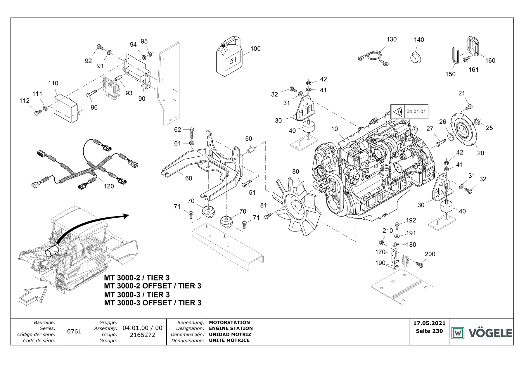
The engine-station plate 04.01.00 / group 2165272 shows the diesel engine as position 10. Alternative diesel-engine part numbers printed on later engine lists include 2162414 (valid 10-9999), 2394500 (valid 165-9999) and 2366903 (valid 170-374). Surrounding hardware on the same family of lists includes coupling 2146195, engine mountings 2144625, rubber buffers 4915520159, engine support brackets 2165262 or 2146400, fan 2165293, and WGP engine oil 15W40 5 L under part 2065020. Separate cooler lists name Motorkühler / engine cooler parts 2428078 and 2428051. None of those lines publish a third-party engine brand string; the catalogue identifies the power unit by Vögele part number and validity band.

Hydraulic coverage begins at group 05.01.00 with the hydraulic tank drawing 2153492: tank body, filters, filler, sight hardware and hose clips, with MA 0,9 Nm and MA 7 Nm called on the plate. Electrical coverage opens at group 06.01.00, 24 V power supply (group 2149665). That drawing locates batteries, cable markers W18 through W33B, torque notes of MA 16 Nm and arrows into further electrical groups 06.03.04, 06.05.03 and 10.06.15. A 230 V / 1 kW warning plate set appears later in the chassis-label section for machines carrying that option.

IMAGES PREVIEW

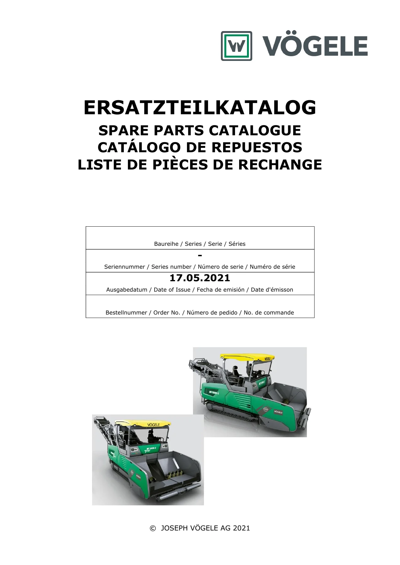
Vogele MT 3000-2 Series 0761 Spare Parts Catalogue 2021 PDF — PDF page 1 preview
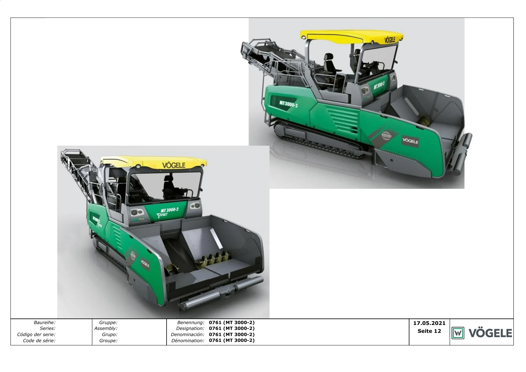
Vogele MT 3000-2 Series 0761 Spare Parts Catalogue 2021 PDF — PDF page 12 preview
Vogele MT 3000-2 Series 0761 Spare Parts Catalogue 2021 PDF — PDF page 230 preview

Travel Drive, Conveyor and Wear-Facing Assemblies

Advance-drive group 08.01.00 documents the left crawler track (Raupe links / group 2199754): track frame, rollers, idler, drive sprocket area, tensioner, hydraulic track adjuster and a boxed MA 520 Nm Loctite X callout. Steering group 09.02.00 / 01 covers the direction indicator mounted on the hopper side. The conveyor section is the largest single block in the table of contents, starting at page 472 with the push-roller (Abdruckrolle / group 2201296) and then running through belts, rollers, scrapers, gates, cables and wear plates for the rest of the material path. Cleaner-unit group 13.01.00 / 02 and lubrication-unit group 18.01.00 close the machine systems with pump, tank, pipe and distributor breakdowns.

Service Kits, Tools and Ordering Rules Printed in the Book

Group 41.01.00 is the 50-hour service kit (Wartungssatz, 50 Std. / group 2184906). Group 42 collects loose accessories and ends with the communication package listing headset 2072800. The introductory pages state the four items required for a clean parts order: machine or assembly type, year of manufacture and serial number; part number and quantity; delivery address and contact; and the required shipment method. The same pages state that parts and extra equipment not supplied by Vögele have not been tested or approved by the publisher, and that liability for damage from non-original parts or unauthorised conversions is excluded.

Identify the Right Part and Order It Correctly

The Vogele MT 3000-2 Series 0761 Spare Parts Catalogue 2021 PDF lets a workshop confirm a drawing position, read the matching Vögele part number and validity band, check quantity and unit, and see the same name in German, English, Spanish and French before the order is placed. That matters on a series 0761 machine because several diesel engines, hoods, coolers and label sets share a similar outline but different validity windows. Using the number printed on the 17.05.2021 list, together with the serial number from the type plate, is the method the catalogue itself sets out. Delivery is an instant PDF download after payment — no shipping wait — so the file can be opened on a shop PC, tablet or phone and printed for the bench or the stores counter.

Reviews

There are no reviews yet.

Be the first to review “Vogele MT 3000-2 Series 0761 Spare Parts Catalogue 2021 PDF”

What Our Customers Say

★★★★★ Live reviews from customers
Loading customer reviews...
0
    0
    Your Cart
    Your cart is emptyReturn to Shop
    🛒
    Recently Purchased
    🕒 verified order