Volkswagen Arteon 2018 – 2021 Repair Manual – PDF DOWNLOAD
$43.95
Volkswagen Arteon 2018 – 2021 Repair Manual – PDF DOWNLOAD
Description
Volkswagen Arteon 2018 – 2021 Repair Manual – PDF DOWNLOAD
FILE DETAILS:
Volkswagen Arteon 2018 – 2021 Repair Manual – PDF DOWNLOAD
Language : English
Pages : 10119
Downloadable : Yes
File Type : PDF
IMAGES PREVIEW OF THE MANUAL:
TABLE OF CONTENTS:
Volkswagen Arteon 2018 – 2021 Repair Manual – PDF DOWNLOAD
D3E8046D49A Wheels and Tyres Guide – General Information 1
44 – Wheels, tyres, vehicle geometry 9
1 Instructions on using the guide 9
1 1 Overview 9
1 1 1 Wheels and Tyres Guide – General Information 9
1 1 2 Wheels and Tyres Guide – Vehicle-specific section 9
1 2 General information 9
1 3 Notes 10
1 4 Determining correct wheel and tyre combinations, according to NEDC with tyre package 11
1 4 1 Determining the required tyre package via PR number 11
1 4 2 Determining the required tyre package via version key in the vehicle registration certificate part 1 11
1 5 Determining correct wheel and tyre combinations according to WLTP 12
1 5 1 Vehicle registration certificate part 1 12
1 5 2 COC document, item 0 10 14
1 6 NEDC, WLTP and RDE 14
1 6 1 What are NEDC, WLTP and RDE? 14
1 6 2 What are the differences between WLTP and RDE? 14
1 6 3 Since when are WLTP and RDE valid? 14
1 7 Definition of tyre package 14
1 8 Explanations regarding world regions 15
2 Legislative and technical conditions 17
2 1 Legislative conditions 17
2 1 1 Permissible wheel and tyre combinations in Germany 17
2 1 2 Vehicles with Tyre Pressure Monitoring System 17
2 2 Technical conditions 18
2 3 Load-carrying capacity depending on vehicle speed, winter tyres 18
2 4 Vehicle registration documents since 01 10 2005 20
2 5 COC document (EEC Certificate of Conformity) 21
2 6 EU general type approval number, sales type and sales or trade designation 21
3 Wheel change 24
3 1 Fitting instructions 24
3 2 Protecting wheel centring seat against corrosion 27
3 3 Fitting wheels 27
3 4 Position of anti-theft wheel bolts for steel wheels 28
4 Fitting tyre 30
4 1 Pressing tyre off wheel rim 30
4 2 Removing tyre sealant 31
4 3 Removing tyre from wheel 31
4 3 1 Removing tyres, wheels without and with tyre pressure monitoring 31
4 3 2 Removing tyres, run-flat tyres, ultra-high-performance tyres 33
4 4 Ensuring proper assembly temperature for tyres 35
4 5 Fitting tyre 36
4 5 1 Mounting tyre, wheels without and with tyre pressure monitoring 36
4 5 2 Mounting tyre, run-flat tyres, ultra-high performance tyres 38
4 6 Matching wheel rims and tyres 40
4 7 Checking radial and lateral runout of wheels and tyres 41
4 7 1 Checking radial and lateral runout of wheels and tyres, tolerances 41
4 7 2 Checking radial and lateral runout on wheels and tyres with tyre gauge 42
4 8 Matching wheels and tyres 43
4 9 Balancing wheel 44
4 9 1 Conditions 44
4 9 2 Balancing wheel on stationary wheel balancer 44
4 9 3 Balancing wheel with finish balancer 47
4 9 4 Checking radial and lateral run-out on wheel rim 48
4 10 Tyre sealant disposal 49
5 Tyre Pressure Monitoring System 50
5 1 System description – Tyre Pressure Monitoring System 50
5 1 1 System description – Tyre Pressure Monitoring System with indirect measurement (Tyre Pressure Loss Indicator) 50
5 1 2 System description – Tyre Pressure Monitoring System with direct measurement (with tyre pressure sensor) 52
5 1 3 Button behaviour – Tyre Pressure Monitoring System with direct measurement (with tyre pressure sensor) 52
5 1 4 System description – Tyre Pressure Monitoring System, Tyre Pressure Monitoring System (TPMS) with autolocation 53
5 2 Overview of fitting locations – Tyre Pressure Monitoring System 54
5 2 1 Overview of fitting locations – Tyre Pressure Monitoring System (TPMS) with autolocation 54
5 2 2 Overview of fitting locations – Tyre Pressure Monitoring System, Trigger 55
5 2 3 Overview of fitting locations – Tyre Pressure Monitoring System, Autolocation 57
5 3 Assembly overview – tyre pressure sensor 58
5 3 1 Assembly overview – tyre pressure sensor, tyre pressure sensor with valve 58
5 3 2 Assembly overview – tyre pressure sensor, tyre pressure sensor without valve, version 1 60
5 3 3 Assembly overview – tyre pressure sensor, tyre pressure sensor without valve, version 2 62
5 4 Removing and installing tyre pressure sensor -G222-/-G223-/-G224-/-G225- 63
5 4 1 Removing and installing tyre pressure sensor, tyre pressure sensor with valve 63
5 4 2 Removing and installing tyre pressure sensor, tyre pressure sensor without valve, version 1 (customer service version) 64
5 4 3 Removing and installing tyre pressure sensor, tyre pressure sensor without valve, version 1 (production version) 66
5 4 4 Removing and installing tyre pressure sensor -G222-/-G223-/-G224-/-G225-, version 2 69
5 5 Removing and installing Tyre Pressure Monitoring System control unit -J502- 71
5 5 1 Removing and installing Tyre Pressure Monitoring System control unit -J502-, Arteon 2018, Arteon 2021, Arteon Shooting Brake 2021, Passat 2015, Passat Estate 2015, Passat 2019, Passat Estate 2019 72
5 5 2 Removing and installing tyre Tyre Pressure Monitoring System control unit, Passat 2011, Passat Estate 2011 74
5 5 3 Removing and installing Tyre Pressure Monitoring System control unit, CC 2010, CC 2012, Passat CC 2009 74
5 5 4 Removing and installing Tyre Pressure Monitoring System control unit, Phaeton 2003 74
5 5 5 Removing and installing Tyre Pressure Monitoring System control unit -J502-, Touran 2016 74
5 5 6 Removing and installing Tyre Pressure Monitoring System control unit -J502-, Tiguan 2008 75
5 5 7 Removing and installing Tyre Pressure Monitoring System control unit -J502-, Tiguan 2016, Tiguan 2017 (BW2), Tiguan 2021 76
5 5 8 Removing and installing Tyre Pressure Monitoring System control unit, up to model year 2014, Touareg 2010 77
5 5 9 Removing and installing Tyre Pressure Monitoring System control unit, as of model year 2015, Touareg 2015 78
5 5 10 Removing and installing Tyre Pressure Monitoring System control unit, Touareg 2018 79
5 5 11 Removing and installing bracket for Tyre Pressure Monitoring System control unit, Touareg 2015 80
5 6 Removing and installing tyre pressure monitor sender unit in wheel housing 80
5 6 1 Removing and installing sender unit for Tyre Pressure Monitoring System in front left/front right wheel housing -G431/G432-, Touareg 2010, Touareg 2015 80
5 6 2 Removing and installing sender unit for Tyre Pressure Monitoring System in rear left/rear right wheel housing -G433/G434-, Touareg 2010, Touareg 2015 81
5 6 3 Removing and installing sender unit for Tyre Pressure Monitoring System in wheel housing, Phaeton 2003 82
6 Wheel bolts 83
6 1 Wheel bolts, versions 83
6 2 Wheel bolts, anti-theft wheel bolt 85
6 3 Wheel bolts, adapter sets for anti-theft wheel bolts 85
7 Information on tyres 88
7 1 Identification markings on the tyre sidewall 88
7 2 Tyre dimension 90
7 3 Load rating code/load index (LI) 90
7 4 Speed rating code 91
7 5 EU tyre label 91
7 5 1 EU tyre label, summary 91
7 5 2 EU tyre label, objectives 92
7 5 3 EU tyre label, categories 93
7 6 Structure of a radial belted tyre 97
7 6 1 Cross section of a radial belted tyre 97
7 6 2 Run-flat tyres, structure and identification of a SST tyre 98
7 6 3 Run-flat tyres, seal inside technology 100
7 7 Run-flat tyre, SST (Self Supporting Tyre) 103
7 7 1 Run-flat tyres – general information 103
7 7 2 Run-flat tyres, retrofitting/requirements when using run-flat tyres 104
7 7 3 Run-flat tyres, repair work 104
7 8 Tyre storage 104
7 9 Reinforced and Extra Load (XL) tyres 105
7 10 M+S tyres 106
7 11 Winter tyres with speed symbol V 108
7 12 All-season tyres 109
7 13 Optimised rolling resistance tyres 110
7 14 Tyre ageing 110
7 15 Tyres with flange protection 112
7 16 Tyre sizes for vehicles with all-wheel drive 112
7 17 Increase in temperature due to insufficient tyre pressure 112
8 Tyre sealant 114
8 1 Models with breakdown set 114
8 2 Storage life 114
8 3 Disposal 114
9 Information about wheels (rims) 115
9 1 Structure of wheel (rim) 115
9 2 Identification 116
9 3 Composite wheels 117
9 4 Care and maintenance of alloy wheel rims 117
9 5 Restoring alloy wheels 117
9 6 Removing and installing hub cover for alloy wheels with open threaded connection 118
9 7 Renewing trim elements 119
9 7 1 Renewing trim elements, bonded trim elements 119
9 7 2 Renewing trim elements, bolted trim elements 123
9 8 Removing and installing valve 124
9 8 1 Removing and installing valve, description of the valve 124
9 8 2 Removing and installing valve, rubber valve 125
9 8 3 Removing and installing valve, metal valve 126
10 Handling problems 128
10 1 Rolling noise 128
10 1 1 General notes on tyre noise 128
10 1 2 Flat spots (from locking wheels) 129
10 2 Vehicle pulls to one side 130
10 2 1 General information 130
10 2 2 Conicity 130
10 2 3 Remedies when vehicle pulls to one side 132
10 2 4 Strategic rotation of wheels for non-directional tyres 133
10 2 5 Strategic rotation of wheels having unidirectional tyres 134
10 3 Vibration 135
10 3 1 Vibration, causes for vibration 135
10 3 2 Vibration, conducting a road test before balancing wheels 135
10 3 3 Vibration, vibration control system 135
10 4 Eliminating flat spots caused by storage or handling 136
11 Evaluating tyres 138
11 1 Flat spots caused by storage or handling 138
11 2 Undulations 138
11 3 Saw-tooth wear 139
11 4 Flat spots caused by hard braking 139
11 5 Swellings in the tyre sidewall 139
11 6 Cuts 141
11 7 Damage caused by foreign bodies 141
11 8 Stripped profile 142
11 9 Tyre damage due to insufficient tyre pressure 142
11 10 Checking tyres 143
11 11 Damage caused when fitting 144
12 Tyre wear 146
12 1 Factors influencing the service life of tyres 146
12 2 Saw-tooth wear 147
12 3 Wear behaviour of high-speed tyres 148
12 4 Measuring tread depth 148
12 5 One-sided wear 149
12 6 Outer shoulder wear 151
12 7 Diagonal washout 152
12 8 Wear in middle of tyre 153
12 9 Permissible deviation in tread depth 153
13 Overview of components 154
13 1 Assembly overview – wheel 154
14 Snow chains 157
14 1 Assembly and use of snow chains 157
15 Regular and temporary spare wheels, recommended temporary spare tyres 158
15 1 Spare wheel with yellow sticker 158
15 2 Temporary spare wheels and recommended temporary spare tyres 159
15 2 1 Atlas 2017 159
15 2 2 Golf 2013, e-Golf 2014 159
15 2 3 Golf 2017, e-Golf 2017 159
15 2 4 Golf SV 2015 159
15 2 5 Golf Variant 2014 160
15 2 6 Golf Variant 2017 160
15 2 7 Golf 2018 (AU2/BX6) 160
15 2 8 Jetta 2018 160
15 2 9 Taos 2021 161
D3E80473F31 Propshaft and rear final drive 162
00 – Technical data 166
1 Safety information 166
1 1 General safety provisions 166
1 2 Safety precautions when using testers and measuring instruments during a road test 167
1 3 Safety measures when working on vehicles with a start/stop system 168
2 Identification 169
2 1 Identification of final drive 169
2 1 1 Final drive code 02D/0BS/0AY 169
2 1 2 Final drive code 0CQ/0CR/0BR 169
3 Repair instructions 171
3 1 General repair instructions 171
3 1 1 General information 171
3 1 2 Oil 171
3 1 3 Locking devices 171
3 1 4 Bearings 171
3 1 5 Shims 172
3 2 Gaskets and seals 172
3 3 Nuts and bolts 172
4 Technical data 174
4 1 Capacities 174
4 1 1 Capacities, final drive 0BS 174
4 1 2 Capacities, final drive 0AY 174
4 1 3 Capacities, final drive 0CQ 174
4 1 4 Capacities, final drive 0CR 175
4 1 5 Capacities, final drive 0BR 175
5 Electrical components 176
5 1 Overview of fitting locations – electrical components 176
5 1 1 Overview of fitting locations – electrical components, rear final drive “0BS” with all-wheel drive coupling generation IV 176
5 1 2 Overview of fitting locations – electrical components, rear final drive “0CQ/0CR/0AY/0BR” with all-wheel drive coupling generation V and VI 176
39 – Final drive – rear differential 178
1 Final drive 178
1 1 Assembly overview – final drive 178
1 1 1 Assembly overview – final drive 178
1 2 Removing and installing final drive 179
1 2 1 Removing and installing final drive, CC 2012 ►, Passat 2011 ►, Passat Estate 2011 ► 179
1 2 2 Removing and installing final drive, Golf 2013 ►, Golf 2017 ► 189
1 2 3 Removing and installing final drive, Golf Estate 2014 ►, Golf Estate 2017 ► 200
1 2 4 Removing and installing final drive, Passat 2015 ►, Passat Estate 2015 ►, Arteon 2018 ►, Passat 2019 ►, Passat Estate 2019 ► 211
1 2 5 Removing and installing rear final drive, Sharan 2016 ► 221
1 2 6 Removing and installing final drive, Tiguan ► 226
1 2 7 Removing and installing final drive, T-Roc 2018 ►, T-Roc 2022 ►, T-Roc Cabriolet 2022 ► 238
1 2 8 Removing and installing final drive, Tarek Russia 2022 ► 249
2 Assembly mountings 260
2 1 Assembly overview – assembly mountings 260
2 1 1 Assembly overview – subframe, rear final drive 0BS, 0CR, 0AY 260
2 1 2 Assembly overview – subframe, rear final drive 0CQ, 0BR 262
2 2 Removing and installing bonded rubber bush 263
2 2 1 Removing and installing bonded rubber bush, rear final drive 0BS, 0CR, 0AY 263
2 2 2 Removing and installing bonded rubber bush, rear final drove 0CQ, 0BR 265
3 Gear oil 272
3 1 Overview of fitting locations – oil drain and inspection plugs 272
3 1 1 Overview of fitting locations – oil drain and inspection plugs, T-Roc 2018 ►, T-Roc 2022 ►, T-Roc Cabriolet 2022 ► 272
3 1 2 Overview of fitting locations – drain and inspection plugs, Tarek Russia 2022 ► 272
3 2 Checking gear oil level 273
4 Oil seals 276
4 1 Overview of fitting locations – oil seals 276
4 2 Renewing right seal 276
4 2 1 Renewing right oil seal, rear final drive 0BS 276
4 2 2 Renewing right oil seal, rear final drive 0CQ, 0CR, 0AY, 0BR 280
4 3 Renewing left seal 283
4 3 1 Renewing left oil seal, rear final drive 0BS 283
4 3 2 Renewing left oil seal, rear final drive 0CQ, 0CR, 0AY, 0BR 287
4 4 Renewing input shaft seal 290
4 4 1 Renewing input shaft seal 290
5 All-wheel drive coupling 299
5 1 Assembly overview – all-wheel drive coupling 299
5 1 1 Assembly overview – all-wheel drive coupling, generation IV 299
5 1 2 Assembly overview – all-wheel drive coupling, generation V and generation VI 301
5 2 Checking function 303
5 3 Checking fluid level in all-wheel drive coupling 303
5 4 Draining and filling high performance fluid for all-wheel drive coupling 304
5 5 Removing and installing all-wheel drive coupling pump -V181- 307
5 5 1 Removing and installing all-wheel drive coupling pump -V181-, generation IV 307
5 5 2 Removing and installing all-wheel drive coupling pump -V181-, generation V and generation VI 309
5 6 Removing and installing all-wheel drive coupling 313
5 6 1 Removing and installing all-wheel drive coupling, generation IV 313
5 6 2 Removing and installing all-wheel drive coupling, generation V 320
5 6 3 Removing and installing all-wheel drive coupling, generation VI 328
5 7 Removing and installing four-wheel drive control unit -J492- 336
5 7 1 Removing and installing all-wheel drive control unit -J492-, generation IV 336
5 7 2 Removing and installing all-wheel drive control unit -J492-, generation V 339
5 7 3 Removing and installing all-wheel drive control unit -J492-, generation VI 340
6 Propshaft 343
6 1 Assembly overview – propshaft 343
6 1 1 Assembly overview – propshaft, CC 2012 ►, Passat ►, Passat Estate ►, Golf ►, Golf Estate ►, Tiguan ►, Arteon ► 343
6 1 2 Assembly overview – propshaft, Sharan 2016 ► 345
6 1 3 Assembly overview – propshaft, T-Roc 2018 ►, T-Roc 2022 ►, T-Roc Cabriolet 2022 ► 346
6 1 4 Assembly overview – propshaft, Tarek Russia 2022 ► 347
6 2 Removing and installing propshaft 349
6 2 1 Removing and installing propshaft, CC 2012 ►, Passat 2011 ►, Passat Estate 2011 ► 349
6 2 2 Removing and installing propshaft, Golf 2013 ►, Golf Estate 2014 ►, Golf 2017 ►, Golf Estate 2017 ► 354
6 2 3 Removing and installing propshaft, Passat 2015 ►, Passat Estate 2015 ►, Arteon, Passat 2019 ►, Passat Estate 2019 ► 359
6 2 4 Removing and installing propshaft, Sharan 2016 ► 366
6 2 5 Removing and installing propshaft, Tiguan ► 372
6 2 6 Removing and installing propshaft, T-Roc 2018 ►, T-Roc 2022 ►, T-Roc Cabriolet 2022 ► 379
6 2 7 Removing and installing propshaft, Tarek Russia 2022 ► 386
6 3 Removing and installing front flexible coupling 393
6 4 Removing and installing rear flexible coupling 396
D4B802E46CA 4 cyl direct injection engine (1 8 l and 2 0 l 4 V EA 888 gen III turbocharger chain drive) 406
00 – Technical data 414
1 Safety information 414
1 1 Safety precautions when working on the fuel supply system 414
1 2 Safety measures when working on vehicles with start/stop system 414
1 3 Safety precautions when using testers and measuring instruments during a road test 415
1 4 Safety precautions when working on the ignition system 415
1 5 Safety precautions when working on the cooling system 415
1 6 Safety precautions when working on the exhaust system 416
2 Identification 417
2 1 Engine number/engine data 417
3 Repair notes 421
3 1 Rules for cleanliness 421
3 2 Foreign material in engine 421
3 3 Contact corrosion 421
3 4 Routing and attachment of lines 421
3 5 Installing radiators and condensers 422
3 6 Checking vacuum system 422
10 – Removing and installing engine 423
1 Removing and installing engine 423
1 1 Removing engine 423
1 2 Separating engine and gearbox 444
1 2 1 Separating engine and gearbox, vehicles with manual gearbox 444
1 2 2 Separating engine and gearbox, vehicles with 7-speed dual clutch gearbox 447
1 2 3 Separating engine and gearbox, vehicles with 6-speed dual clutch gearbox 449
1 2 4 Separating engine and gearbox, vehicles with automatic gearbox 452
1 3 Securing engine on engine and gearbox support 454
1 4 Installing engine 457
2 Assembly mountings 461
2 1 Assembly overview – assembly mountings 461
2 1 1 Assembly overview – assembly mountings, Golf, Passat, Touran, Tiguan, Arteon 461
2 1 2 Assembly overview – assembly mountings, Sharan 463
2 2 Supporting engine in installation position 465
2 2 1 Supporting engine in installation position, Arteon 465
2 2 2 Supporting engine in installation position, Golf, Touran 469
2 2 3 Supporting engine in installation position, Passat 474
2 2 4 Supporting engine in installation position, Sharan 479
2 2 5 Supporting engine in installation position, Tiguan 482
2 3 Removing and installing engine mounting 486
2 4 Removing and installing gearbox mountings 488
2 5 Removing and installing pendulum support 490
2 5 1 Removing and installing pendulum support, Golf, Passat, Touran, Tiguan, Arteon 490
2 5 2 Removing and installing pendulum support, Sharan 491
2 6 Checking adjustment of assembly mountings 491
2 7 Adjusting assembly mountings 492
3 Engine cover panel 495
3 1 Removing and installing engine cover 495
13 – Crankshaft group 496
1 Cylinder block (pulley end) 496
1 1 Assembly overview – cylinder block (pulley end) 496
1 2 Removing and installing poly V-belts 499
1 3 Removing and installing poly V-belt tensioner 501
1 4 Removing and installing vibration damper 502
1 5 Removing and installing bracket for ancillaries 509
1 6 Removing and installing engine support 512
1 7 Renewing seal for vibration damper 514
2 Cylinder block (gearbox end) 517
2 1 Assembly overview – cylinder block (gearbox end) 517
2 2 Removing and installing flywheel 518
2 3 Removing and installing sealing flange (gearbox end) 520
3 Crankshaft 525
3 1 Assembly overview – crankshaft 525
3 2 Crankshaft dimensions 527
3 3 Allocation of main bearing shells 527
3 4 Renewing needle bearing in crankshaft 529
3 5 Measuring axial clearance of crankshaft 531
3 6 Measuring radial clearance of crankshaft 532
3 7 Removing and installing sender wheel 533
4 Balance shaft 535
4 1 Assembly overview – balance shaft 535
4 2 Removing and installing balance shaft 537
4 2 1 Removing and installing inlet side balance shaft 537
4 2 2 Removing and installing exhaust side balance shaft 540
4 2 3 Renewing oil seal for balance shaft (inlet side) 542
5 Pistons and conrods 544
5 1 Assembly overview – pistons and conrods 544
5 2 Removing and installing pistons 548
5 3 Checking pistons and cylinder bores 550
5 4 Separating parts of new conrod 553
5 5 Checking radial clearance of conrod bearings 553
5 6 Removing and installing oil spray jets 554
15 – Cylinder head, valve gear 556
1 Cylinder head 556
1 1 Assembly overview – cylinder head 556
1 2 Removing and installing cylinder head 559
1 3 Removing and installing vacuum pump 567
1 4 Checking compression 568
2 Timing chain cover 571
2 1 Assembly overview – timing chain cover 571
2 2 Removing and installing timing chain cover 573
2 2 1 Removing and installing upper timing chain cover 573
2 2 2 Removing and installing timing chain cover (bottom) 576
3 Chain drive 582
3 1 Assembly overview – camshaft timing chains 582
3 2 Removing and installing camshaft timing chain 585
3 3 Assembly overview – drive chain for balance shaft 601
3 4 Removing and installing drive chain for balance shaft 604
3 5 Checking timing chain 604
3 6 Checking valve timing 605
4 Valve gear 608
4 1 Assembly overview – valve gear 608
4 2 Removing and installing camshaft 613
4 3 Removing and installing camshaft control valve 1 -N205- 632
4 4 Removing and installing exhaust camshaft control valve 1 -N318- 632
4 5 Removing and installing valve stem oil seals 632
4 5 1 Removing and installing valve stem seals (cylinder head installed) 632
4 5 2 Removing and installing valve stem seals (cylinder head removed) 638
5 Inlet and exhaust valves 644
5 1 Checking valve guides 644
5 2 Checking valves 645
5 3 Valve dimensions 645
17 – Lubrication 646
1 Sump/oil pump 646
1 1 Assembly overview – sump/oil pump 646
1 2 Removing and installing oil level and oil temperature sender -G266- 649
1 3 Removing and installing lower part of sump 650
1 3 1 Removing and installing bottom section of sump, plastic sump 650
1 3 2 Removing and installing bottom section of sump, sheet-metal sump 651
1 4 Removing and installing oil pump 656
1 5 Removing and installing upper part of sump 659
1 6 Engine oil 664
2 Engine oil cooler 665
2 1 Assembly overview – engine oil cooler 665
2 2 Removing and installing engine oil cooler 665
3 Crankcase breather 668
3 1 Assembly overview – crankcase breather system 668
3 2 Removing and installing oil separator 669
4 Oil filter/oil pressure switches 670
4 1 Assembly overview – oil filter 670
4 2 Assembly overview – oil pressure switches/oil pressure control 670
4 3 Removing and installing piston cooling jet control valve -N522- 672
4 4 Removing and installing valve for oil pressure control -N428- 673
4 5 Removing and installing oil pressure switch 674
4 5 1 Removing and installing oil pressure switch -F1- 674
4 5 2 Removing and installing oil pressure switch for reduced oil pressure -F378- 675
4 5 3 Removing and installing stage 3 oil pressure switch -F447- 676
4 6 Checking oil pressure 678
4 6 1 Checking engine oil pressure 678
4 6 2 Checking oil pressure and oil spray jets 680
19 – Cooling 682
1 Cooling system/coolant 682
1 1 Connection diagram – coolant hoses 682
1 1 1 Vehicles with manual gearbox 682
1 1 2 Vehicles with dual clutch gearbox or automatic gearbox 683
1 1 3 Vehicles with dual clutch gearbox, engine code CHHA 685
1 1 4 Vehicles with dual clutch gearbox and auxiliary radiator on right side 687
1 1 5 Vehicles with dual clutch gearbox and auxiliary radiator on right and left sides 689
1 1 6 Sharan with additional heat exchanger 691
1 2 Draining and filling cooling system 692
1 3 Checking cooling system for leaks 701
1 4 Flushing cooling system 705
1 4 1 Flushing cooling system 705
1 4 2 Flushing cooling system, quick reference guide 727
2 Coolant pump/thermostat assembly 729
2 1 Assembly overview – coolant pump/thermostat 729
2 2 Assembly overview – electric coolant pump 731
2 3 Assembly overview – coolant temperature sender 735
2 4 Removing and installing toothed belt for coolant pump 736
2 5 Removing and installing coolant pump 738
2 6 Removing and installing electric coolant pump 741
2 6 1 Removing and installing auxiliary pump for heating -V488- 741
2 7 Removing and installing coolant valves 744
2 7 1 Removing and installing coolant shut-off valve -N82- 744
2 7 2 Removing and installing coolant valve for gearbox -N488-, vehicles with 6-speed dual clutch gearbox 746
2 7 3 Removing and installing coolant valve for gearbox -N488-, vehicles with 7-speed dual clutch gearbox 748
2 7 4 Removing and installing coolant valve for gearbox -N488-, vehicles with automatic gearbox 749
2 8 Removing and installing actuator for engine temperature regulation -N493- 751
2 9 Removing and installing coolant temperature sender -G62- 754
2 10 Removing and installing radiator outlet coolant temperature sender -G83- 755
3 Coolant pipes 757
3 1 Assembly overview – coolant pipes 757
3 2 Removing and installing coolant pipes 757
3 2 1 Removing and installing front coolant pipe 757
3 3 Removing and installing upper coolant pipes 759
4 Radiators/radiator fans 762
4 1 Assembly overview – radiator 762
4 1 1 Assembly overview – radiator, Golf, Passat, Touran, Tiguan, Arteon 762
4 1 2 Assembly overview – radiator/radiator fan, Sharan 764
4 2 Assembly overview – auxiliary radiator 766
4 2 1 Assembly overview – right auxiliary radiator 766
4 2 2 Assembly overview – left auxiliary radiator 767
4 3 Assembly overview – radiator cowl and radiator fans 767
4 3 1 Assembly overview – radiator cowl and radiator fan, Golf, Passat, Arteon 767
4 3 2 Assembly overview – radiator cowl and radiator fan, Sharan 768
4 3 3 Assembly overview – radiator cowl and radiator fan, Touran, Tiguan 769
4 4 Removing and installing radiator 770
4 4 1 Removing and installing radiator, Golf, Passat, Touran, Tiguan, Arteon 770
4 4 2 Removing and installing radiator, Sharan 773
4 5 Removing and installing radiator cowl 778
4 6 Removing and installing radiator fan 781
4 6 1 Removing and installing radiator fan, Golf, Passat, Arteon 781
4 6 2 Removing and installing radiator fan, Sharan 781
4 6 3 Removing and installing radiator fan, Touran, Tiguan 782
4 7 Removing and installing auxiliary radiator 783
4 7 1 Removing and installing right auxiliary radiator 783
4 7 2 Removing and installing left auxiliary radiator 785
21 – Turbocharging/supercharging 788
1 Turbochargers 788
1 1 Assembly overview – turbochargers 788
1 2 Removing and installing turbochargers 794
1 2 1 Removing and installing turbocharger, Golf, Passat, Tiguan, Arteon 794
1 2 2 Removing and installing turbocharger, Sharan, Touran 801
1 3 Removing and installing charge pressure positioner -V465- 806
1 4 Adjusting charge pressure positioner -V465- 807
2 Charge air system 811
2 1 Assembly overview – charge air system 811
2 1 1 Assembly overview – charge air system, Golf, Passat, Touran, Tiguan, Arteon 811
2 1 2 Assembly overview – charge air system, Sharan 813
2 2 Assembly overview – hose connections for charge air system 815
2 3 Removing and installing charge air cooler 815
2 3 1 Removing and installing charge air cooler, Golf, Passat, Touran, Tiguan, Arteon 815
2 3 2 Removing and installing charge air cooler, Sharan 820
2 4 Removing and installing charge pressure sender -G31- 821
2 5 Checking charge air system for leaks 821
2 6 Removing and installing air intake pipe between turbocharger and charge air cooler 824
24 – Mixture preparation – injection 826
1 Injection system 826
1 1 Overview of fitting locations – injection system 826
2 Injectors 838
2 1 Assembly overview – fuel rail with injectors 838
2 1 1 Assembly overview – fuel rail with injectors, direct injection 838
2 1 2 Assembly overview – fuel rail with injectors, indirect injection 840
2 2 Removing and installing fuel rail 840
2 3 Removing and installing injectors 841
2 3 1 Removing and installing injectors, direct injection 841
2 3 2 Removing and installing injectors, indirect injection 846
2 4 Renewing seals on injector 849
2 5 Cleaning injectors 852
3 Air filter 855
3 1 Assembly overview – air filter housing 855
3 2 Removing and installing air filter housing 857
4 Intake manifold 859
4 1 Assembly overview – intake manifold 859
4 2 Removing and installing intake manifold 861
4 3 Removing and installing throttle valve module -GX3- 867
4 4 Cleaning throttle valve module -GX3- 870
5 Senders and sensors 872
5 1 Assembly overview – actuator for structure-borne sound and control unit for structure-borne sound, Golf, Passat, Touran, Tiguan 872
5 2 Assembly overview – actuator for structure-borne sound and control unit for structure-borne sound, Arteon 873
5 3 Removing and installing fuel pressure sender -G247- 874
5 4 Checking fuel pressure sender -G247- 878
5 4 1 Checking fuel pressure sender -G247- using pressure sensor tester -VAS 6394- 878
5 4 2 Checking fuel pressure sender -G247- using vehicle diagnostic tester (Guided Functions) 881
5 5 Removing and installing fuel pressure sender for low-pressure -G410- 883
5 6 Removing and installing intake manifold sender -GX9- 884
5 7 Removing and installing pressure differential sender for particulate filter -G1037- 885
6 Engine/motor control unit 887
6 1 Removing and installing motor control unit -J623- 887
6 1 1 Removing and installing engine control unit -J623-, Golf, Passat, Touran, Tiguan, Arteon 887
6 1 2 Removing and installing engine control unit -J623-, Sharan 888
6 2 Removing and installing engine control unit -J623- with protective housing 891
6 2 1 Removing and installing engine control unit -J623- with protective housing, Golf, Passat, Touran, Tiguan, Arteon 891
6 2 2 Removing and installing engine control unit -J623- with protective housing, Sharan 894
7 High-pressure pump 900
7 1 Assembly overview – high-pressure pump 900
7 2 Removing and installing high-pressure pump 902
7 3 Removing and installing high-pressure pipe 906
8 Lambda probe 910
8 1 Assembly overview – Lambda probe 910
8 2 Removing and installing Lambda probe 911
8 2 1 Removing and installing Lambda probe 1 before catalytic converter -GX10- 911
8 2 2 Removing and installing Lambda probe 1 after catalytic converter -GX7- 913
26 – Exhaust system 915
1 Exhaust pipes/silencers 915
1 1 Assembly overview – silencers 915
1 1 1 Assembly overview – silencer, Golf, front-wheel drive 915
1 1 2 Assembly overview – silencers, titanium version 917
1 1 3 Assembly overview – silencers, Golf CJSB; Passat CJXA, DNUA; Arteon 919
1 1 4 Assembly overview – silencers, Passat with engine codes CJSA, CJSC 921
1 1 5 Assembly overview – silencer, Passat CHHB, CXDA 923
1 1 6 Assembly overview – silencers, Sharan 925
1 1 7 Assembly overview – silencers, Touran 925
1 1 8 Assembly overview – silencers, Tiguan 927
1 2 Removing and installing silencers 928
1 2 1 Removing and installing silencer, Golf, front-wheel drive 928
1 2 2 Removing and installing silencers, Golf CJSB; Passat CJXA, DNUA; Arteon 930
1 2 3 Removing and installing silencer, Passat with engine codes CJSA, CJSC 931
1 2 4 Removing and installing silencer, Passat CHHB, CXDA 934
1 2 5 Removing and installing silencer, Sharan 936
1 2 6 Removing and installing silencer, Touran 936
1 2 7 Removing and installing silencer, Tiguan 937
1 3 Separating exhaust pipes/silencers 939
1 3 1 Separating exhaust pipes/silencers, Golf, front-wheel drive 939
1 3 2 Separating exhaust pipes silencers, Passat with engine codes CJSA, CJSC 940
1 3 3 Separating exhaust pipes and silencers, Passat CHHB, CJXA, CXDA, DNUA; Golf CJSB; Arteon 942
1 3 4 Separating exhaust pipes/silencers, Touran 945
1 4 Stress-free alignment of exhaust system 946
1 5 Checking exhaust system for leaks 947
2 Emission control system 948
2 1 Assembly overview – emission control system 948
2 1 1 Assembly overview – emission control, Golf, Passat, Touran, Arteon 948
2 1 2 Assembly overview – exhaust gas treatment, Sharan 951
2 1 3 Assembly overview – exhaust gas treatment, Tiguan 952
2 1 4 Assembly overview – emission control, vehicles with particulate filter and front-wheel drive 957
2 1 5 Assembly overview – emission control, vehicles with particulate filter and all-wheel drive 960
2 2 Assembly overview – bracket and pipes for pressure differential sender for particulate filter -G1037- 963
2 3 Removing and installing catalytic converter 964
2 3 1 Removing and installing catalytic converter, vehicles without particulate filter 964
2 3 2 Removing and installing catalytic converter, vehicles with particulate filter and front-wheel drive 972
2 3 3 Removing and installing catalytic converter, vehicles with particulate filter and all-wheel drive 976
2 4 Removing and installing holder of pressure differential sender for particulate filter -G1037- 981
2 5 Removing and installing exhaust flap control unit -J883/J945-, Passat CJXA, Arteon 982
3 Exhaust gas temperature regulation 983
3 1 Assembly overview – exhaust gas temperature regulation 983
3 2 Removing and installing parts of exhaust gas temperature regulation 984
3 2 1 Removing and installing exhaust gas temperature sender, vehicles with front-wheel drive 984
3 2 2 Removing and installing exhaust gas temperature sender, vehicles with all-wheel drive 986
4 Secondary air system 989
4 1 Assembly overview – secondary air system 989
4 2 Removing and installing secondary air pump motor -V101- 990
4 3 Renewing stop buffer for secondary air pump 990
4 4 Removing and installing secondary air inlet valve -N112- 991
28 – Ignition system 993
1 Ignition system 993
1 1 Assembly overview – ignition system 993
1 2 Removing and installing ignition coils with output stage 995
1 3 Removing and installing knock sensor 1 -G61- 997
1 4 Removing and installing Hall sender 999
1 4 1 Removing and installing Hall sender -G40- 999
1 4 2 Removing and installing Hall sender 3 -G300- 999
1 5 Removing and installing engine speed sender -G28- 1000
D4B804A2FD3 Brake system 1002
00 – Technical data 1006
1 Safety information 1006
1 1 Safety precautions when using testers and measuring instruments during a road test 1006
2 Identification 1007
2 1 Allocation of PR number – brakes 1007
2 1 1 Front brakes, Passat, Passat Estate 1007
2 1 2 Front brake, Arteon 1007
2 1 3 Rear brakes, Passat, Passat Estate 1008
2 1 4 Rear brakes, Arteon 1008
3 Technical data 1010
3 1 Technical data for brakes 1010
3 1 1 Brake master cylinder and brake servo 1010
4 Brake test 1013
4 1 General information 1013
4 2 Checking vehicles with front-wheel drive 1013
4 3 Checking vehicles with all-wheel drive 1013
4 3 1 On a regulated roller dynamometer with counter-rotating rollers for four-wheel drive vehicles 1013
4 3 2 Without roller dynamometer for four-wheel drive vehicles 1014
4 4 Checking parking brake 1014
4 4 1 Checking electromechanical parking brake, vehicles with front-wheel drive 1014
4 4 2 Checking electromechanical parking brake, vehicles with all-wheel drive 1015
45 – Anti-lock brake system 1016
1 General information 1016
1 1 Repair instructions for repair work on ABS 1016
2 Overview of fitting locations 1019
2 1 Overview of fitting locations – ABS/ESP 1019
3 Control unit and hydraulic unit 1021
3 1 Assembly overview – control unit and hydraulic unit 1021
3 1 1 Assembly overview – control unit and hydraulic unit, LHD 1021
3 1 2 Assembly overview – control unit and hydraulic unit, right-hand drive 1023
3 2 Removing and installing ABS control unit -J104- and ABS hydraulic unit -N55- 1025
3 2 1 Removing and installing control unit and hydraulic unit, left-hand drive, petrol engines 1025
3 2 2 Removing and installing control unit and hydraulic unit, left-hand drive vehicles with diesel engine 1029
3 2 3 Removing and installing control unit and hydraulic unit, right-hand drive 1036
3 2 4 Removing and installing control unit and hydraulic unit, LHD vehicles, bi-turbo diesel engine 1040
3 3 Connecting brake lines to hydraulic unit 1047
3 3 1 Connecting brake lines to hydraulic unit, LHD 1047
3 3 2 Connecting brake lines to hydraulic unit, RHD 1048
3 4 Separating control unit from hydraulic unit 1049
3 5 Fitting control unit to hydraulic unit 1050
4 Sensors 1052
4 1 Assembly overview – speed sensor on front axle 1052
4 2 Assembly overview – speed sensor on rear axle 1053
4 2 1 Assembly overview – speed sensor on rear axle, front-wheel drive 1053
4 2 2 Assembly overview – speed sensor on rear axle, all-wheel drive 1054
4 3 Removing and installing speed sensors on front axle -G45-/-G47- 1054
4 4 Removing and installing speed sensors on rear axle -G44-/-G46- 1055
4 4 1 Removing and installing speed sensor on rear axle -G44-/-G46-, vehicles with front-wheel drive 1055
4 4 2 Removing and installing speed sensor on rear axle -G44-/-G46-, vehicles with all-wheel drive 1056
4 5 Checking ABS sensor ring 1056
4 6 Removing and installing ESP sensor unit -G419- 1057
4 7 Removing and installing steering angle sender -G85- 1058
46 – Brakes – mechanism 1059
1 Front brake 1059
1 1 Assembly overview – front brake 1059
1 1 1 Assembly overview – front brake 1059
1 2 Removing and installing brake pads 1061
1 2 1 Removing and installing brake pads, front brakes 1061
1 3 Removing and installing brake caliper 1064
1 3 1 Removing and installing brake caliper 1064
2 Rear brake 1066
2 1 Assembly overview – rear brakes 1066
2 2 Removing and installing brake pads 1068
2 3 Removing and installing brake caliper 1072
3 Parking brake 1077
3 1 Overview of fitting locations – parking brake 1077
3 2 Removing and installing control unit for electromechanical parking brake -J540- 1078
3 3 Removing and installing parking brake motor -V282-/-V283- 1078
4 Brake pedal 1081
4 1 Assembly overview – brake pedal 1081
4 1 1 Assembly overview – brake pedal, left-hand drive 1081
4 1 2 Assembly overview – brake pedal, right-hand drive 1083
4 2 Separating brake pedal from brake servo 1084
4 3 Connecting brake pedal to brake servo 1085
4 4 Removing and installing brake pedal 1085
4 4 1 Removing and installing brake pedal, left-hand drive vehicles 1085
4 5 Removing and installing mounting bracket 1086
4 5 1 Removing and installing mounting bracket, left-hand drive 1086
4 5 2 Removing and installing mounting bracket, RHD 1088
47 – Brakes – hydraulics 1091
1 Front brake caliper 1091
1 1 Assembly overview – front brake caliper 1091
1 1 1 Assembly overview – brake caliper PC57 and C60 1091
1 2 Removing and installing brake caliper piston 1092
1 2 1 Removing and installing PC57 brake caliper piston 1092
2 Rear brake caliper 1095
2 1 Assembly overview – rear brake caliper 1095
2 2 Removing and installing protective cap 1095
3 Brake servo and brake master cylinder 1099
3 1 Assembly overview – brake servo/brake master cylinder 1099
3 1 1 Assembly overview – brake servo/brake master cylinder, left-hand drive vehicles 1099
3 1 2 Assembly overview – brake servo/brake master cylinder, right-hand drive 1101
3 1 3 Assembly overview – electromechanical brake servo/brake master cylinder, left-hand drive vehicles 1104
3 1 4 Assembly overview – electromechanical brake servo/brake master cylinder, right-hand drive vehicles 1105
3 2 Removing and installing brake light switch 1107
3 2 1 Removing and installing brake light switch, LHD 1107
3 2 2 Removing and installing brake light switch, right-hand drive 1108
3 3 Removing and installing brake master cylinder 1109
3 3 1 Removing and installing brake master cylinder, left-hand drive 1109
3 3 2 Removing and installing brake master cylinder, RHD 1113
3 3 3 Removing and installing brake master cylinder, LHD vehicles, bi-turbo diesel engine 1120
3 3 4 Removing and installing brake master cylinder, e-brake servo, left-hand drive vehicles 1123
3 3 5 Removing and installing brake master cylinder, electromechanical brake servo, right-hand drive vehicles 1128
3 4 Removing and installing brake servo 1134
3 4 1 Removing and installing brake servo, LHD vehicles, petrol engine 1134
3 4 2 Removing and installing brake servo, left-hand drive vehicles with diesel engine 1140
3 4 3 Removing and installing brake servo, LHD vehicles, bi-turbo diesel engine 1146
3 4 4 Removing and installing brake servo, right-hand drive vehicles with petrol engine 1151
3 4 5 Removing and installing brake servo, right-hand drive with diesel engine 1155
3 4 6 Removing and installing electromechanical brake servo, left-hand drive vehicles 1157
3 4 7 Removing and installing electromechanical brake servo, right-hand drive vehicles 1159
4 Vacuum system 1163
4 1 Assembly overview – vacuum pump 1163
4 1 1 Assembly overview – vacuum pump, vehicles with diesel engine 1163
4 1 2 Assembly overview – vacuum pump, vehicles with 1 8 l and 2 0 l petrol engine 1163
4 1 3 Assembly overview of vacuum pump for brakes -V192-, vehicles with 1 4 l petrol engine 1164
4 1 4 Assembly overview of vacuum pump for brakes -V192-, vehicles with 1 5 l petrol engine 1165
4 2 Checking non-return valve 1167
4 3 Removing and installing vacuum sender -G608- 1167
4 4 Removing and installing electric vacuum pump 1167
4 5 Checking vacuum system 1168
4 5 1 Connecting vacuum gauge for brake servo -VAS 6721- 1169
4 5 2 Checking vacuum generation 1170
4 5 3 Checking for leaks 1170
5 Brake lines 1173
5 1 Repairing brake lines 1173
5 1 1 Assembly overview – flanging tool 1175
5 1 2 Work instructions 1175
6 Hydraulic system 1178
6 1 General notes on brake fluid 1178
6 1 1 Changing brake fluid 1178
6 2 Pre-bleeding hydraulic system 1178
6 3 Bleeding hydraulic system following standard procedure 1180
6 4 Subsequent bleeding of hydraulic system 1181
6 5 Testing for leaks 1182
D4B804A2FD4 Fuel supply system petrol engines 1183
00 – Technical data 1187
1 Safety information 1187
1 1 Safety regulations for working on fuel supply 1187
1 2 Safety precautions when using testers and measuring instruments during a road test 1187
1 3 Safety measures when working on vehicles with a start/stop system 1188
2 Identification 1189
2 1 Engine number/engine data 1189
3 General information 1191
3 1 Rules for cleanliness when working on auxiliary heater and fuel system 1191
4 Repair instructions 1192
4 1 Routing and attachment of lines 1192
4 2 General repair instructions 1192
20 – Fuel supply system 1193
1 Fuel 1193
1 1 Assembly overview – fuel tank 1193
1 1 1 Assembly overview – fuel tank, Passat and Arteon with front-wheel drive 1193
1 1 2 Assembly overview – fuel tank, Tiguan with front-wheel drive 1195
1 1 3 Assembly overview – fuel tank, vehicles with four-wheel drive 1197
1 1 4 Renewing seal for cap 1199
1 2 Removing and installing fuel tank 1200
1 2 1 Removing and installing fuel tank – Passat and Arteon with front-wheel drive 1200
1 2 2 Removing and installing fuel tank – Tiguan with front-wheel drive 1206
1 2 3 Removing and installing fuel tank – vehicles with four-wheel drive 1213
1 2 4 Checking earth cable on filler neck from fuel tank 1222
1 3 Emptying fuel tank 1223
1 3 1 Emptying fuel tank when fuel pump is intact 1223
1 3 2 Emptying fuel tank if more than 3/4 full, Passat and Arteon 1226
1 3 3 Emptying fuel tank if more than 3/4 full, Tiguan 1228
1 3 4 Emptying fuel tank less than 3/4 full, vehicles with front-wheel drive 1230
1 3 5 Emptying fuel tank less than 3/4 full, vehicles with four-wheel drive 1233
2 Fuel delivery unit, fuel gauge sender 1238
2 1 Assembly overview – fuel delivery unit/fuel gauge sender 1238
2 1 1 Assembly overview – fuel delivery unit/fuel gauge sender, vehicles with front-wheel drive 1238
2 1 2 Assembly overview – fuel delivery unit/fuel gauge sender, vehicles with four-wheel drive 1240
2 1 3 Assembly overview – fuel delivery unit/fuel gauge sender, vehicles with auxiliary heater 1243
2 1 4 Assembly overview – fuel delivery unit/left fuel gauge sender 1245
2 2 Removing and installing fuel delivery unit, fuel gauge sender 1247
2 2 1 Removing and installing fuel delivery unit/fuel gauge sender, vehicles with front-wheel drive 1247
2 2 2 Removing and installing fuel delivery unit/fuel gauge sender, vehicles with four-wheel drive 1252
2 2 3 Removing and installing fuel line for auxiliary/supplementary heater 1258
2 3 Removing and installing fuel gauge sender -G- 1260
2 3 1 Removing and installing fuel gauge sender -G-, vehicles with front-wheel drive 1260
2 3 2 Removing and installing fuel gauge sender -G-, vehicles with four-wheel drive 1261
2 4 Removing and installing fuel gauge sender 2 -G169- 1262
2 5 Removing and installing assembly opening cover 1267
2 5 1 Removing and installing assembly opening cover, Passat and Arteon 1267
2 5 2 Removing and installing assembly opening cover, Tiguan 1268
3 Plug-in connectors 1270
3 1 Separating plug-in connectors 1270
4 Fuel filter 1277
5 Activated charcoal filter system 1278
5 1 Connection diagram – activated charcoal filter system 1278
5 1 1 Connection diagram – activated charcoal filter system, vehicles with fuel tank leak diagnosis 1278
5 1 2 Connection diagram – activated charcoal filter system, engine compartment, vehicles with 1 5 l engine from model year 2020 1279
5 1 3 Connection diagram – activated charcoal filter system, engine compartment, vehicles with 1 4 l engine from model year 2020 1280
5 2 Assembly overview – activated charcoal filter system 1281
5 2 1 Assembly overview – activated charcoal filter system with fuel tank leak diagnosis 1281
5 2 2 Assembly overview – activated charcoal filter without fuel tank leak diagnosis 1282
5 3 Removing and installing activated charcoal filter 1284
5 3 1 Removing and installing activated charcoal filter, vehicles with fuel tank leak diagnosis 1284
5 3 2 Removing and installing air filter for activated charcoal filter system, vehicles with fuel tank leak detection 1285
5 3 3 Removing and installing activated charcoal filter, vehicles without fuel tank leak diagnosis 1286
5 4 Removing and installing fuel system diagnosis pump 1288
5 5 Checking fuel tank breather, vehicles without fuel tank leak diagnosis 1289
5 6 Checking fuel system for leaks, vehicles with fuel tank leak diagnosis 1295
5 6 1 Checking fuel system for leaks, with exhaust-smoke tester -KLI 9210- 1295
5 6 2 Checking fuel system for leaks, with exhaust-smoke tester -VAS 523 005- 1298
6 Accelerator pedal 1307
6 1 Assembly overview – accelerator module 1307
6 2 Removing and installing accelerator pedal module -GX2- 1307
7 Fuel pump 1309
7 1 Checking fuel system pressurisation pump -G6-, EA888evo 1309
7 2 Checking fuel system pressurisation pump -G6-, EA211, EA888 1317
7 2 1 Checking fuel pressure in engine compartment 1317
7 2 2 Checking pressure at fuel delivery unit -GX1- 1319
7 2 3 Checking fuel delivery rate of fuel system pressurisation pump -G6- in engine compartment 1321
7 2 4 Checking fuel delivery rate at fuel delivery unit -GX1- 1324
7 2 5 Connecting test instrument adapter for voltage measurement at fuel delivery unit 1327
7 2 6 Connecting remote control 1330
7 3 Removing and installing suction-jet pump 1333
7 4 Removing and installing fuel pump control unit -J538- 1335
7 4 1 Removing and installing control unit for fuel pump -J538-, Passat and Arteon 1335
7 4 2 Removing and installing fuel pump control unit -J538-, Tiguan 1336
7 5 Checking suction-jet pump 1337
8 Senders and sensors 1339
8 1 Assembly overview – fuel quality sender 1339
8 2 Removing and installing fuel quality sender -G446- 1340
9 Fuel lines 1341
9 1 Removing and installing fuel lines 1341
D4B804A2FD5 Fuel supply system diesel engines 1347
00 – Technical data 1351
1 Safety information 1351
1 1 Safety regulations for working on fuel supply 1351
1 2 Safety measures when working on vehicles with start/stop system 1352
1 3 Safety precautions when using testers and measuring instruments during a road test 1352
1 4 Safety precautions when working on SCR system 1352
2 Identification 1354
2 1 Engine number/engine data 1354
3 General information 1355
3 1 Rules for cleanliness when working on auxiliary heater and fuel system 1355
4 Repair instructions 1356
4 1 Rules for cleanliness 1356
4 2 Foreign bodies in engine 1356
4 3 Contact corrosion 1356
4 4 Routing and attachment of lines 1357
4 5 Fitting radiator and condensers 1357
20 – Fuel supply system 1358
1 Procedure in event of misfuelling 1358
1 1 Procedure in event of misfuelling 1358
1 1 1 Step 1, engine was started with incorrect fuel 1358
1 1 2 Step 2, engine was not started with incorrect fuel 1360
1 1 3 Step 3, there are metal particles in fuel delivery unit and fuel tank 1362
1 1 4 Step 4, there are no metal particles in fuel delivery unit or fuel tank 1363
1 1 5 Step 5, there are metal particles in high-pressure pump 1365
1 1 6 Step 6, there are no metal particles in high-pressure pump 1365
2 Fuel 1367
2 1 Assembly overview – fuel tank 1367
2 1 1 Assembly overview – fuel tank, Passat and Arteon with front-wheel drive 1367
2 1 2 Assembly overview – fuel tank, Tiguan with front-wheel drive 1369
2 1 3 Assembly overview – fuel tank, vehicles with four-wheel drive 1371
2 1 4 Renewing seal for cap 1373
2 2 Removing and installing fuel tank 1374
2 2 1 Removing and installing fuel tank – Passat and Arteon with front-wheel drive 1374
2 2 2 Removing and installing fuel tank – Tiguan with front-wheel drive 1380
2 2 3 Removing and installing fuel tank – vehicles with four-wheel drive 1388
2 3 Emptying fuel tank 1396
2 3 1 Emptying fuel tank when fuel pump is intact 1396
2 3 2 Emptying fuel tank if more than 3/4 full, Passat and Arteon 1398
2 3 3 Emptying fuel tank if more than 3/4 full, Tiguan 1400
2 3 4 Emptying fuel tank less than 3/4 full, vehicles with front-wheel drive 1402
2 3 5 Emptying fuel tank less than 3/4 full, vehicles with four-wheel drive 1404
2 4 Removing and installing misfuelling prevention device 1409
2 4 1 Removing and installing misfuelling prevention device, plastic cap 1409
2 4 2 Removing and installing misfuelling prevention device, metal cap 1412
2 5 Deactivating misfuelling prevention device 1413
2 5 1 Deactivating the misfuelling prevention device, plastic cap 1413
2 5 2 Deactivating the misfuelling prevention device, metal cap 1414
3 Fuel delivery unit, fuel gauge sender 1415
3 1 Assembly overview – fuel delivery unit/fuel gauge sender 1415
3 1 1 Assembly overview – fuel delivery unit/fuel gauge sender, vehicles with front-wheel drive 1415
3 1 2 Assembly overview – fuel delivery unit/fuel gauge sender, vehicles with four-wheel drive 1418
3 1 3 Assembly overview- fuel gauge sender, left, all-wheel drive 1421
3 2 Removing and installing fuel delivery unit, fuel gauge sender 1423
3 2 1 Removing and installing fuel delivery unit/fuel gauge sender, vehicles with front-wheel drive 1423
3 2 2 Removing and installing fuel delivery unit/fuel gauge sender, vehicles with four-wheel drive 1428
3 3 Removing and installing fuel gauge sender -G- 1433
3 3 1 Removing and installing fuel gauge sender -G-, vehicles with front-wheel drive 1433
3 3 2 Removing and installing fuel gauge sender -G-, vehicles with four-wheel drive 1434
3 4 Removing and installing fuel gauge sender 2 -G169- 1434
3 5 Removing and installing assembly opening cover 1439
3 5 1 Removing and installing assembly opening cover, Passat and Arteon 1439
3 5 2 Removing and installing assembly opening cover, Tiguan 1440
4 Plug-in connectors 1441
4 1 Separating plug-in connectors 1441
5 Fuel filter 1448
5 1 Assembly overview – fuel filter 1448
5 1 1 Assembly overview – fuel filter 1448
5 1 2 Assembly overview – fuel filter, vehicles with water separator sender -G63- 1448
5 2 Removing and installing fuel filter 1449
5 3 Fuel hoses in the engine compartment 1453
6 Accelerator pedal 1455
6 1 Assembly overview – accelerator module 1455
6 2 Removing and installing accelerator pedal module -GX2- 1455
7 Fuel supply 1457
7 1 Checking fuel system pressurisation pump -G6- 1457
7 1 1 Checking fuel pressure 1457
7 1 2 Checking fuel delivery rate 1465
7 1 3 Checking low pressure fuel system, EA288evo 1474
7 2 Removing and installing suction-jet pump 1478
7 3 Removing and installing fuel pump control unit -J538- 1483
7 3 1 Removing and installing control unit for fuel pump -J538-, Passat and Arteon 1483
7 3 2 Removing and installing fuel pump control unit -J538-, Tiguan 1484
7 4 Checking suction-jet pump 1485
8 Fuel lines 1487
8 1 Removing and installing fuel lines 1487
8 2 Removing and installing fuel line for auxiliary/supplementary heater 1492
9 Senders and sensors 1495
9 1 Removing and installing water separator sender -G63- 1495
D4B804A2FDC 4 cylinder common rail engine (2 0 l 4V bi turbo EA 288) 1496
00 – Technical data 1504
1 Safety information 1504
1 1 Safety regulations for working on fuel supply 1504
1 2 Safety measures when working on vehicles with start/stop system 1505
1 3 Safety precautions when using testers and measuring instruments during a road test 1505
1 4 Safety precautions when working on the cooling system 1505
1 5 Safety precautions when working on SCR system 1505
1 6 Safety precautions when working on exhaust system 1506
2 Identification 1508
2 1 Engine number/engine data 1508
3 Repair instructions 1510
3 1 Rules for cleanliness 1510
3 2 Foreign objects in engine 1510
3 3 Contact corrosion 1510
3 4 Routing and attachment of lines 1511
3 5 Fitting radiator and condensers 1511
10 – Removing and installing engine 1512
1 Removing and installing engine 1512
1 1 Removing engine 1512
1 2 Separating engine and gearbox 1524
1 3 Securing engine on engine and gearbox support 1527
1 4 Installing engine 1528
2 Assembly mountings 1533
2 1 Assembly overview – assembly mountings 1533
2 1 1 Assembly overview – assembly mountings, Passat and Arteon 1533
2 1 2 Assembly overview – assembly mountings, Tiguan 1535
2 2 Removing and installing engine mounting 1537
2 3 Removing and installing gearbox mounting 1539
2 3 1 Removing and installing gearbox mounting, Passat and Arteon 1539
2 3 2 Removing and installing gearbox mountings, Tiguan 1541
2 4 Removing and installing pendulum support 1543
2 5 Supporting engine in installation position 1544
2 5 1 Supporting engine in installation position, Passat 1544
2 5 2 Supporting engine in installation position, Tiguan 1549
2 5 3 Supporting engine in installation position, Arteon 1555
2 6 Adjusting assembly mountings 1561
2 6 1 Adjusting assembly mountings, Passat and Arteon 1561
2 6 2 Adjusting assembly mountings, Tiguan 1562
2 7 Checking adjustment of assembly mountings 1564
3 Engine cover panel 1565
3 1 Removing and installing engine cover 1565
13 – Crankshaft group 1566
1 Cylinder block (pulley end) 1566
1 1 Assembly overview – cylinder block (pulley end) 1566
1 2 Assembly overview – sealing flange, belt pulley end 1569
1 3 Removing and installing poly-V belt 1571
1 4 Removing and installing tensioner for poly V-belt 1572
1 5 Removing and installing vibration damper 1573
1 6 Removing and installing bracket for ancillaries 1574
1 7 Removing and installing engine support 1576
1 8 Removing and installing sealing flange on pulley end 1578
1 9 Renewing caps in cylinder block (pulley end) 1581
2 Cylinder block, gearbox end 1584
2 1 Assembly overview – cylinder block, gearbox end 1584
2 2 Removing and installing flywheel 1587
2 3 Removing and installing sealing flange on gearbox side 1589
2 4 Renewing caps in cylinder block (gearbox end) 1599
3 Crankshaft 1601
3 1 Assembly overview – crankshaft 1601
3 2 Crankshaft dimensions 1601
3 3 Renewing needle bearing in crankshaft 1601
3 4 Measuring axial clearance of crankshaft 1604
4 Pistons and conrods 1606
4 1 Assembly overview – pistons and conrods 1606
4 2 Removing and installing pistons 1609
4 3 Measuring piston projection at TDC 1611
4 4 Checking pistons and cylinder bores 1613
4 5 Separating new conrod 1615
4 6 Checking radial clearance of conrods 1616
15 – Cylinder head, valve gear 1617
1 Cylinder head 1617
1 1 Assembly overview – cylinder head 1617
1 2 Assembly overview – cylinder head cover 1621
1 2 1 Assembly overview – cylinder head cover 1621
1 2 2 Assembly overview – cylinder head cover with add-on parts 1623
1 3 Removing and installing cylinder head 1624
1 4 Removing and installing cylinder head cover 1631
1 5 Removing and installing injector seals 1634
1 6 Removing and installing camshaft housing 1636
1 7 Checking compression 1640
2 Toothed belt drive 1643
2 1 Assembly overview – toothed belt cover 1643
2 2 Assembly overview – toothed belt 1643
2 3 Removing and installing toothed belt guard 1645
2 3 1 Removing and installing upper toothed belt guard 1645
2 3 2 Removing and installing lower toothed belt guard 1649
2 4 Removing and installing toothed belt 1651
2 5 Removing toothed belt from camshaft 1666
3 Valve gear 1672
3 1 Assembly overview – valve gear 1672
3 2 Measuring axial play of camshaft 1675
3 3 Removing and installing camshaft oil seal 1675
3 4 Checking hydraulic compensation elements 1678
3 5 Removing and installing valve stem seals 1679
3 5 1 Removing and installing valve stem seals (cylinder head installed) 1679
3 5 2 Removing and installing valve stem seals (cylinder head removed) 1682
4 Inlet and exhaust valves 1687
4 1 Checking valve guides 1687
4 2 Checking valves 1688
4 3 Valve dimensions 1688
17 – Lubrication 1689
1 Sump, oil pump 1689
1 1 Assembly overview – sump/oil pump 1689
1 2 Engine oil: 1691
1 3 Removing and installing oil sump 1691
1 4 Removing and installing oil pump 1696
1 5 Removing and installing oil level and oil temperature sender -G266- 1697
2 Engine oil cooler 1699
3 Oil filter, oil pressure switch 1700
3 1 Assembly overview – oil filter housing, oil pressure switch 1700
3 2 Removing and installing oil pressure switch -F1- 1702
3 3 Removing and installing oil pressure switch for reduced oil pressure -F378- 1704
3 4 Checking oil pressure 1706
3 5 Removing and installing oil filter housing 1706
3 6 Removing and installing oil pressure regulating valve -N428- 1709
19 – Cooling 1712
1 Cooling system/coolant 1712
1 1 Connection diagram – coolant hoses 1712
1 2 Checking cooling system for leaks 1714
1 3 Draining coolant 1718
1 4 Filling with coolant 1720
1 4 1 Filling with coolant without electric vacuum pump 1720
1 4 2 Filling coolant with electric vacuum pump -VAS 6096/2- 1728
1 4 3 Checking electric vacuum pump -VAS 6096/2- 1739
1 5 Checking filling quality of cooling system 1740
1 6 Flushing cooling system 1742
1 6 1 Flushing cooling system, quick reference guide 1765
2 Coolant pump, regulation of cooling system 1767
2 1 Assembly overview – coolant pump, thermostat 1767
2 1 1 Assembly overview – coolant pump/thermostat, version 1 1767
2 1 2 Assembly overview – coolant pump/thermostat, version 2 1769
2 2 Assembly overview – electric coolant pump 1771
2 3 Assembly overview – coolant temperature sender 1773
2 3 1 Assembly overview – coolant temperature sender -G62- 1773
2 3 2 Assembly overview – coolant temperature sender 2 -G802- 1773
2 4 Assembly overview – actuator for engine temperature regulation -N493- 1774
2 4 1 Assembly overview – actuator for engine temperature regulation -N493-, Passat and Arteon 1774
2 4 2 Assembly overview – actuator for engine temperature regulation -N493-, Tiguan 1775
2 5 Removing and installing electric coolant pump 1776
2 5 1 Removing and installing charge air cooling pump -V188- 1776
2 5 2 Removing and installing auxiliary pump for heating -V488- 1779
2 6 Removing and installing coolant pump 1782
2 7 Removing and installing thermostat 1783
2 7 1 Removing and installing thermostat, version 1 1783
2 7 2 Removing and installing thermostat, version 2 1784
2 8 Checking thermostat 1787
2 9 Removing and installing coolant valve for cylinder head -N489- 1788
2 10 Removing and installing coolant temperature sender -G62- 1788
2 11 Removing and installing coolant temperature sender 2 -G802- 1790
2 12 Removing and installing actuator for engine temperature regulation -N493- 1792
2 12 1 Removing and installing actuator for engine temperature regulation -N493-, Passat and Arteon 1792
2 12 2 Removing and installing actuator for engine temperature regulation -N493-, Tiguan 1795
3 Coolant pipes 1799
3 1 Assembly overview – coolant pipes 1799
3 2 Removing and installing coolant pipes 1803
3 2 1 Removing and installing upper front coolant pipe 1803
3 2 2 Removing and installing front coolant pipes 1804
3 2 3 Removing and installing front coolant connection 1806
3 2 4 Removing and installing coolant pipe at front below intake manifold 1807
3 2 5 Removing and installing front right coolant pipe 1808
3 2 6 Removing and installing lower front coolant pipe 1810
3 2 7 Removing and installing left coolant pipes 1813
3 2 8 Removing and installing rear coolant pipe 1815
3 2 9 Removing and installing rear right coolant pipe 1818
3 2 10 Upper left coolant pipe on cylinder head cover 1820
3 2 11 Removing and installing upper left coolant pipes 1822
3 2 12 Removing and installing coolant pipes on turbocharger 1825
4 Radiator, radiator fan 1828
4 1 Assembly overview – radiator/radiator fan 1828
4 2 Assembly overview – auxiliary radiator 1830
4 3 Assembly overview – radiator cowl and radiator fan 1831
4 4 Removing and installing radiator 1832
4 5 Removing and installing water radiator for charge air cooling circuit 1835
4 6 Removing and installing radiator cowl 1838
4 6 1 Removing and installing radiator cowl, Passat 1838
4 6 2 Removing and installing radiator cowl, Tiguan and Arteon 1840
4 7 Removing and installing radiator fan 1841
4 7 1 Removing and installing radiator fan -V7- 1841
4 7 2 Removing and installing radiator fan -V177- 1842
4 8 Removing and installing auxiliary radiator 1842
21 – Turbocharging/supercharging 1846
1 Turbocharger 1846
1 1 Assembly overview – turbocharger 1846
1 1 1 Assembly overview – turbocharger 1846
1 1 2 Assembly overview – heat shields on turbocharger 1848
1 1 3 Assembly overview – coolant lines on turbocharger 1849
1 1 4 Assembly overview – high-pressure turbocharger 1850
1 1 5 Assembly overview – low-pressure turbocharger 1852
1 1 6 Assembly overview – turbocharger/exhaust manifold 1854
1 1 7 Assembly overview – senders and sensors on turbocharger 1856
1 1 8 Assembly overview – oil lines on turbochargers 1857
1 2 Removing and installing turbocharger 1859
1 2 1 Removing and installing high-pressure turbocharger 1859
1 2 2 Removing and installing low-pressure turbocharger 1864
1 3 Removing and installing vacuum unit for turbocharger 1871
1 3 1 Removing and installing vacuum unit with regulating flap potentiometer -G584- on low-pressure turbocharger 1871
1 3 2 Removing and installing vacuum unit for wastegate on low-pressure turbocharger 1874
1 4 Removing and installing turbocharger 1 control unit -J724- 1877
2 Charge air system 1882
2 1 Assembly overview – charge air system 1882
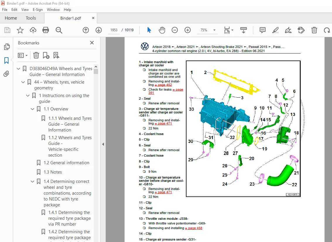
2 2 Removing and installing charge pressure sender -G31- 1884
2 3 Removing and installing charge pressure sender 2 -G447- 1884
2 4 Checking charge air system for leaks 1885
2 5 Removing and installing air pipe 1887
2 6 Checking charge air cooler for leaks 1894
23 – Mixture preparation – injection 1900
1 Injection system 1900
1 1 Schematic overview – fuel system 1900
1 2 Overview of fitting locations – injection system 1901
1 2 1 Overview of fitting locations – injection system, engine compartment 1901
1 2 2 Overview of fitting locations – injection system, engine from above 1905
1 2 3 Overview of fitting locations – injection system, front view of engine 1907
1 2 4 Overview of fitting locations – injection system, rear view of engine 1910
1 2 5 Overview of fitting locations – injection system, engine from left 1912
1 2 6 Overview of fitting locations – electrical connectors, Passat and Arteon 1913
1 2 7 Overview of fitting locations – electrical connectors, Tiguan 1914
1 3 Filling/bleeding fuel system 1915
1 4 Checking fuel system for leaks 1915
2 Vacuum system 1917
2 1 Connection diagram – vacuum system 1917
2 1 1 Connection diagram – vacuum system 1917
2 1 2 Overview of fitting locations – vacuum system 1919
2 2 Checking vacuum system 1920
3 Injectors/high-pressure accumulator (rail) 1922
3 1 Assembly overview – injectors 1922
3 2 Assembly overview – fuel rail 1924
3 3 Adapting correction values for injectors 1926
3 4 Testing injectors 1927
3 5 Checking return flow rate of injectors with engine running 1927
3 6 Checking return flow rate of injectors at starter speed 1930
3 7 Removing and installing injectors 1932
3 8 Removing and installing high-pressure lines 1936
3 8 1 Removing high-pressure pipe between fuel rail and high-pressure pump 1936
3 8 2 Removing and installing high-pressure line between fuel rail and injectors 1937
3 9 Removing and installing fuel rail 1942
4 Air filter 1946
4 1 Assembly overview – air filter housing 1946
4 2 Removing and installing air filter housing 1948
5 Intake manifold 1952
5 1 Assembly overview – intake manifold 1952
5 2 Removing and installing intake manifold 1955
5 3 Removing and installing throttle valve module -J338- 1961
6 Senders and sensors 1964
6 1 Removing and installing fuel pressure regulating valve -N276- 1964
6 2 Checking fuel pressure regulating valve -N276- 1966
6 3 Removing and installing fuel pressure sender -G247- 1968
6 4 Removing and installing air mass meter -G70- 1969
6 5 Removing and installing pressure differential sender -G505- 1971
6 6 Removing and installing exhaust gas pressure sensor 1 -G450- 1972
6 7 Removing and installing charge air temperature sender ahead of charge air cooler -G810- 1974
6 8 Removing and installing charge air temperature sender after charge air cooler -G811- 1974
6 9 Removing and installing fuel temperature sender -G81- 1975
6 10 Removing and installing control unit for NOx sender -GX30- 1976
6 10 1 Removing and installing control unit for NOx sender -GX30-, Passat and Arteon 1976
6 10 2 Removing and installing control unit for NOx sender -GX30-, Tiguan 1978
6 11 Assembly overview – NOx sender control unit -GX30- 1980
6 12 Removing and installing control unit 2 for NOx sender -GX46- 1981
6 13 Removing and installing particle sensor -G784- 1983
7 Engine control unit 1985
7 1 Removing and installing engine control unit -J623- 1985
7 1 1 Removing and installing engine control unit -J623- 1985
7 1 2 Removing and installing engine control unit -J623- (with metal locking plate) 1986
7 1 3 Removing and installing engine control unit -J623- (with protective housing) 1989
8 High-pressure pump 1993
8 1 Assembly overview – high-pressure pump 1993
8 2 Removing and installing high-pressure pump 1995
9 Lambda probe 1999
9 1 Assembly overview – Lambda probe 1999
9 2 Removing and installing Lambda probe 1999
9 2 1 Removing and installing Lambda probe 1 before catalytic converter -GX10- 1999
26 – Exhaust system 2002
1 Exhaust pipes and silencers 2002
1 1 Assembly overview – silencers 2002
1 1 1 Assembly overview – silencers, Passat and Arteon 2002
1 1 2 Assembly overview – silencers, Tiguan 2004
1 2 Removing and installing front exhaust pipe 2006
1 2 1 Removing and installing front exhaust pipe, Passat and Arteon 2006
1 2 2 Removing and installing front exhaust pipe, Tiguan 2007
1 3 Removing and installing rear silencer 2009
1 3 1 Removing and installing rear silencer, Passat and Arteon 2009
1 3 2 Removing and installing rear silencer, Tiguan 2011
1 4 Aligning exhaust system free of stress 2013
1 5 Checking exhaust system for leaks 2013
1 6 Installation position of clamp 2014
1 7 Assembly overview – front exhaust pipe 2014
1 7 1 Assembly overview – front exhaust pipe, Passat and Arteon 2014
1 7 2 Assembly overview – front exhaust pipe, Tiguan 2015
1 7 3 Assembly overview – front exhaust pipe, vehicles with control unit 2 for NOx sender -GX46- and particulate sensor -G784- 2018
2 Emission control 2021
2 1 Assembly overview – emission control 2021
2 2 Removing and installing emission control module 2028
2 3 Removing and installing exhaust flap control unit -J883- 2032
3 SCR system (selective catalytic reduction) 2035
3 1 Assembly overview – reducing agent tank 2035
3 1 1 Assembly overview – reducing agent tank, Passat and Arteon 2035
3 1 2 Assembly overview – tank for reducing agent, Tiguan 2037
3 2 Assembly overview – reducing agent supply line 2039
3 3 Assembly overview – delivery module for reducing agent 2040
3 4 Removing and installing reducing agent tank 2041
3 4 1 Removing and installing reducing agent tank, Passat and Arteon 2041
3 4 2 Removing and installing tank for reducing agent, Tiguan 2044
3 5 Removing and installing front section of reducing agent supply line 2047
3 5 1 Removing and installing front section of reducing agent supply line, Passat and Arteon 2047
3 5 2 Removing and installing front section of reducing agent supply line, Tiguan 2054
3 6 Removing and installing delivery module for reducing agent 2062
3 7 Removing and installing injector for reduction agent -N474- 2064
3 8 Removing and installing control unit for reducing-agent heater -J891- 2067
3 8 1 Removing and installing control unit for reducing agent heater -J891-, Passat Variant 2067
3 8 2 Removing and installing control unit for reducing agent heater -J891-, Passat saloon 2068
3 8 3 Removing and installing control unit for reducing-agent heater -J891-, Tiguan 2069
3 8 4 Removing and installing control unit for reducing agent heater -J891-, Arteon 2070
3 9 Assembly overview – injector for reducing agent 2071
3 10 Draining reducing agent tank 2072
3 10 1 Draining reducing agent tank, Passat and Arteon 2072
3 10 2 Emptying tank for reducing agent, Tiguan 2076
3 11 Removing and installing rear section of reducing agent supply line 2079
3 12 Removing and installing filler pipe for reducing agent tank 2081
3 12 1 Removing and installing filler pipe for reducing agent tank, Passat and Arteon 2081
3 12 2 Removing and installing filler tube for reducing agent tank, Tiguan 2082
3 13 Disconnecting reducing agent supply line 2085
3 14 SCR – resetting learnt values 2088
4 Exhaust gas temperature regulation 2089
4 1 Assembly overview – exhaust gas temperature regulation 2089
4 2 Removing and installing exhaust gas temperature sender 1 -G235- 2091
4 3 Removing and installing exhaust gas temperature sender 2 -G448- 2097
4 4 Removing and installing exhaust gas temperature sender 3 -G495- 2099
4 5 Removing and installing exhaust gas temperature sender 4 -G648- 2100
5 Exhaust gas recirculation 2103
5 1 Assembly overview – exhaust gas recirculation 2103
5 1 1 Assembly overview – exhaust gas recirculation, exhaust gas recirculation valve 2 -GX6- 2103
5 1 2 Assembly overview – exhaust gas recirculation, exhaust gas recirculation valve 1 -GX5- 2105
5 2 Removing and installing exhaust gas recirculation cooler 2106
5 3 Removing and installing exhaust gas recirculation valve 1 -GX5- 2112
5 4 Removing and installing exhaust gas recirculation valve 2 -GX6- 2114
5 5 Checking exhaust gas recirculation cooler for leaks 2117
6 Exhaust manifold 2118
6 1 Assembly overview – exhaust manifold 2118
6 2 Removing and installing exhaust manifold 2119
28 – Glow plug system 2121
1 Glow plug system 2121
1 1 Assembly overview – glow plug system 2121
1 2 Removing and installing glow plug 2122
1 3 Removing and installing automatic glow period control unit -J179- 2126
1 4 Removing and installing Hall sender -G40- 2126
1 5 Removing and installing engine speed sender -G28- 2127
D4B804A2FDD Running gear axles steering 2129
00 – Technical data 2135
1 Safety information 2135
1 1 Safety measures when working on vehicles with a start/stop system 2135
1 2 Safety precautions when working on high-voltage system 2135
1 3 Safety precautions when working in the vicinity of high-voltage components 2136
1 4 Safety precautions when working on subframe 2136
2 Repair instructions 2137
2 1 Leaks at shock absorbers 2137
2 2 Noises from shock absorbers 2137
2 3 Checking shock absorbers when removed 2138
2 4 Steering rack 2138
2 5 Gaskets and seals 2139
2 6 Nuts and bolts 2139
2 7 Electrical components 2139
2 8 Raising suspension to unladen position (vehicles with coil springs) 2140
3 Evaluating accident vehicles 2144
3 1 Check list for evaluating running gear on accident vehicles 2144
4 Disposal 2146
4 1 Releasing gas and draining front gas-filled shock absorbers 2146
4 1 1 Releasing gas and draining front gas-filled shock absorbers, conventional shock absorbers 2146
4 1 2 Releasing gas and draining front gas-filled shock absorbers, DCC shock absorbers 2147
4 2 Releasing gas and draining rear gas-filled shock absorbers 2148
4 2 1 Releasing gas and draining rear gas-filled shock absorbers, conventional shock absorbers 2148
4 2 2 Releasing gas and draining rear gas-filled shock absorbers, DCC shock absorbers 2148
40 – Front suspension 2150
1 Front axle 2150
1 1 Overview of fitting locations – front axle 2150
2 Subframe 2153
2 1 Assembly overview – subframe 2153
2 2 Removing and installing subframe without steering rack 2153
2 3 Removing and installing subframe with steering rack 2159
2 4 Repairing subframe 2167
2 5 Repairing thread in longitudinal member 2180
2 6 Fixing subframe in position 2180
2 7 Lowering subframe 2184
3 Anti-roll bar 2190
3 1 Assembly overview – anti-roll bar 2190
3 2 Removing and installing anti-roll bar 2190
3 3 Removing and installing coupling rod 2196
4 Suspension strut, upper suspension link 2198
4 1 Assembly overview – suspension strut, upper suspension link 2198
4 2 Removing and installing suspension strut 2199
4 3 Repairing suspension strut 2210
5 Lower suspension link, swivel joint 2215
5 1 Assembly overview – lower suspension link, swivel joint 2215
5 2 Removing and installing lower suspension link 2216
5 2 1 Removing and installing lower suspension link, vehicle with manual gearbox or dual clutch gearbox 0CW 2216
5 2 2 Removing and installing lower suspension link, vehicle with dual clutch gearbox 0D9, 0DD, except Passat GTE 2219
5 2 3 Removing and installing lower suspension link, vehicle with dual clutch gearbox 0DL, 0GC and Passat GTE 2224
5 3 Checking swivel joint 2230
5 4 Removing and installing swivel joint 2230
5 5 Renewing front bonded rubber bush for lower suspension link 2235
5 6 Renewing rear bonded rubber bush for lower suspension link 2239
6 Wheel bearing 2243
6 1 Assembly overview – wheel bearing assembly 2243
6 2 Removing and installing wheel bearing housing 2243
6 3 Removing and installing wheel bearing unit 2250
7 Drive shaft 2255
7 1 Overview – drive shaft 2255
7 2 Assembly overview – drive shaft 2256
7 2 1 Assembly overview – drive shaft, constant velocity joint VL100 2256
7 2 2 Assembly overview – drive shaft, constant velocity joint VL107 2258
7 2 3 Assembly overview – drive shaft, triple roller joint AAR3300i 2260
7 3 Removing and installing drive shaft 2262
7 3 1 Removing and installing drive shaft, constant velocity joints VL100 and VL107 2262
7 3 2 Removing and installing drive shaft, triple roller joint AAR3300i pushed into gearbox 2268
7 3 3 Removing and installing drive shaft, triple roller joint AAR3300i pushed onto flange shaft 2274
7 3 4 Removing and installing drive shafts, triple roller joint AAR3300i bolted 2279
7 4 Loosening and tightening threaded connections of drive shaft 2284
7 5 Removing and installing drive shaft heat shield 2285
7 6 Dismantling and assembling drive shaft 2286
7 6 1 Dismantling and assembling drive shaft, constant velocity joint VL100 2286
7 6 2 Dismantling and assembling drive shaft, constant velocity joint VL107 2291
7 6 3 Dismantling and assembling drive shaft, triple roller joint AAR3300i pushed into gearbox, bolted on 2297
7 6 4 Dismantling and assembling drive shaft, triple roller joint AAR3300i pushed onto flange shaft 2303
7 7 Checking outer constant velocity joint 2310
7 8 Checking inner constant velocity joint 2311
42 – Rear suspension 2315
1 Rear axle 2315
1 1 Overview – rear axle 2315
1 2 Lowering rear axle 2317
1 2 1 Lowering rear axle, front-wheel drive except Passat GTE 2317
1 2 2 Lowering rear axle, front-wheel drive only Passat GTE 2320
1 2 3 Lowering rear axle, four-wheel drive 2324
1 3 Removing and installing rear axle 2327
1 3 1 Removing and installing rear axle, front-wheel drive, except Passat GTE 2327
1 3 2 Removing and installing rear axle, front-wheel drive, only Passat GTE 2331
1 3 3 Removing and installing rear axle, all-wheel drive 2336
1 4 Removing and installing shield for rear axle 2341
2 Subframe 2343
2 1 Assembly overview – subframe 2343
2 1 1 Assembly overview – subframe, multi-link suspension, front-wheel drive 2343
2 1 2 Assembly overview – subframe, multi-link suspension, four-wheel drive 2343
2 2 Assembly overview – add-on parts for subframe 2344
2 3 Fixing subframe in position 2345
2 3 1 Fixing position of subframe, front-wheel drive except Passat GTE 2345
2 3 2 Fixing position of subframe, front-wheel drive, only Passat GTE 2350
2 3 3 Fixing position of subframe, four-wheel drive 2355
2 4 Repairing subframe 2360
2 4 1 Renewing bonded rubber bush 2360
2 4 2 Renewing rear bonded rubber bush 2367
3 Anti-roll bar 2375
3 1 Assembly overview – anti-roll bar 2375
3 1 1 Assembly overview – anti-roll bar, multi-link suspension, front-wheel drive 2375
3 1 2 Assembly overview – anti-roll bar, multi-link suspension, four-wheel drive 2375
3 2 Removing and installing anti-roll bar 2376
3 3 Removing and installing coupling rod 2378
4 Suspension link, track rod 2381
4 1 Assembly overview – transverse link 2381
4 1 1 Assembly overview – transverse link, multi-link suspension, front-wheel drive 2381
4 1 2 Assembly overview – transverse link, multi-link suspension, four-wheel drive 2383
4 2 Assembly overview – track rod 2385
4 2 1 Assembly overview – track rod, multi-link suspension, front-wheel drive 2385
4 2 2 Assembly overview – track rod, multi-link suspension, four-wheel drive 2385
4 3 Removing and installing upper transverse link 2386
4 4 Removing and installing lower transverse link 2387
4 5 Removing and installing track rod 2389
5 Suspension strut, shock absorber, spring 2392
5 1 Assembly overview – suspension strut, shock absorber, spring 2392
5 2 Removing and installing shock absorber 2393
5 3 Repairing shock absorber 2397
5 4 Removing and installing spring 2399
6 Wheel bearing assembly, trailing arm 2407
6 1 Assembly overview – wheel bearing assembly 2407
6 1 1 Assembly overview – suspension, multi-link suspension, front-wheel drive 2407
6 1 2 Assembly overview – suspension, multi-link suspension, four-wheel drive 2408
6 2 Assembly overview – trailing arm 2409
6 3 Removing and installing wheel bearing housing 2410
6 3 1 Removing and installing wheel bearing housing, multi-link suspension, front-wheel drive 2410
6 3 2 Removing and installing wheel bearing housing, multi-link suspension, four-wheel drive 2416
6 4 Removing and installing wheel bearing unit 2422
6 4 1 Removing and installing wheel bearing unit, multi-link suspension, front-wheel drive 2422
6 4 2 Removing and installing wheel bearing unit, multi-link suspension, four-wheel drive 2427
6 5 Renewing bonded rubber bush for wheel bearing housing 2430
6 6 Removing and installing trailing arm with mounting bracket 2433
6 7 Repairing trailing arm 2437
6 7 1 Repairing trailing arm, hydro-bush 2437
6 7 2 Repairing trailing arm, conventional bearing 2442
7 Drive shaft 2448
7 1 Assembly overview – drive shaft 2448
7 1 1 Assembly overview – drive shaft, constant velocity joint VL90 2448
7 1 2 Assembly overview – drive shaft, constant velocity joint VL100i 2450
7 2 Loosening and tightening threaded connections of drive shaft 2452
7 3 Removing and installing drive shaft 2453
7 4 Dismantling and assembling drive shaft 2461
7 5 Checking outer constant velocity joint 2466
7 6 Checking inner constant velocity joint 2468
43 – Self-levelling suspension 2471
1 Electronic damping control 2471
1 1 Overview of fitting locations – electronically controlled damping system 2471
1 2 Removing and installing electronically controlled damping control unit -J250- 2473
1 2 1 Removing and installing electronically controlled damping control unit -J250-, Passat Saloon 2473
1 2 2 Removing and installing electronically controlled damping control unit -J250-, Passat Estate, Arteon 2474
1 3 Removing and installing front body acceleration senders -G341-/-G342- 2476
1 4 Removing and installing rear left body acceleration sender -G699- 2478
1 4 1 Removing and installing rear left body acceleration sender -G699-, Passat Saloon 2478
1 4 2 Removing and installing rear left body acceleration sender -G699-, Passat Estate 2479
1 4 3 Removing and installing rear left body acceleration sender -G699-, Arteon 2481
2 Vehicle level sender 2483
2 1 Assembly overview – front vehicle level senders 2483
2 2 Assembly overview – rear vehicle level senders 2484
2 2 1 Assembly overview – rear vehicle level senders, multi-link suspension, front-wheel drive 2484
2 2 2 Assembly overview – rear vehicle level senders, multi-link suspension, four-wheel drive 2485
2 3 Removing and installing front vehicle level senders -G78-/-G289- 2485
2 4 Removing and installing rear vehicle level senders -G76-/-G77- 2487
2 4 1 Removing and installing rear left vehicle level sender -G76-, multi-link suspension, front-wheel drive 2487
2 4 2 Removing and installing rear left vehicle level sender -G76-, multi-link suspension, four-wheel drive 2488
44 – Wheels, tyres, vehicle geometry 2490
1 Wheel alignment 2490
1 1 Notes for wheel alignment 2490
1 2 Conditions for testing 2491
1 3 Test preparations 2491
1 3 1 Test preparations, wheel alignment with no driver assist systems 2491
1 3 2 Test preparations, wheel alignment with driver assist systems 2493
1 4 Specifications for wheel alignment 2493
1 4 1 Specifications for wheel alignment, Passat Estate 2493
1 4 2 Specified values for wheel alignment, Arteon 2495
1 5 Wheel alignment procedure 2496
1 6 Necessity of wheel alignment 2498
1 7 Vehicle data sticker 2499
1 8 Adjusting camber at front wheels 2499
1 9 Adjusting camber on rear axle 2501
1 10 Adjusting toe at rear axle 2503
1 11 Adjusting front axle toe 2503
1 12 Wheel runout compensation 2505
1 13 Checking maximum steering wheel angle 2505
2 Adaptive cruise control 2507
2 1 Calibrating adaptive cruise control 2507
2 1 1 Calibrating adaptive cruise control, Passat, Passat Estate ► 08 2018 2507
2 1 2 Calibrating adaptive cruise control, Passat, Passat Estate, Arteon 08 2018 ► 2514
3 Front camera for assist systems 2519
3 1 Calibrating front camera for driver assist systems 2519
48 – Steering 2527
1 Steering wheel 2527
1 1 Assembly overview – steering wheel 2527
1 2 Removing and installing steering wheel 2527
2 Steering column 2530
2 1 Assembly overview – steering column 2530
2 2 Checking steering column for damage 2531
2 3 Handling and transporting steering column 2532
2 4 Removing and installing steering column 2533
2 5 Removing and installing control unit for electronic steering column lock -J764- 2543
3 Steering rack 2546
3 1 Assembly overview – steering rack 2546
3 1 1 Assembly overview – steering rack, left-hand drive 2546
3 1 2 Assembly overview – steering rack, right-hand drive 2548
3 1 3 Assembly overview – steering rack, track rods 2549
3 2 Removing and installing steering rack 2551
3 3 Removing and installing bellows 2562
3 4 Removing and installing track rod 2565
3 5 Removing and installing track rod ball joint 2570
3 6 Repairing steering rack 2572
3 6 1 Removing and installing threaded bush 2572
4 Sensors 2577
4 1 Removing and installing steering angle sender -G85- 2577
D4B804A300A 7 speed dual clutch gearbox 0DL 2578
00 – Technical data 2582
1 Safety information 2582
1 1 General safety provisions 2582
1 2 Safety measures when working on vehicles with a start/stop system 2583
1 3 Notes on tow-starting/towing 2583
1 4 Safety precautions when using testers and measuring instruments during a road test 2583
2 Identification 2585
2 1 Gearbox identification 2585
3 Repair instructions 2586
3 1 General information 2586
3 2 Rules for cleanliness 2587
3 3 General repair instructions 2587
3 4 Gaskets and seals 2588
3 5 Nuts and bolts 2589
4 Technical data 2590
4 1 Capacities 2590
5 Electrical components 2591
5 1 Overview of fitting locations – electrical components 2591
30 – Clutch 2592
1 Clutch 2592
1 1 Assembly overview – dual clutch 2592
1 2 Removing and installing clutch end cover 2593
1 3 Removing dual clutch 2598
1 4 Installing dual clutch 2601
34 – Controls, housing 2612
1 Mechatronic unit 2612
1 1 Removing and installing mechatronic unit for dual clutch gearbox -J743- (gearbox installed) 2612
1 2 Removing and installing gearbox input speed sender -G182- and oil temperature sender in multi-plate clutch -G509- up to gearbox date 05/15 2620
2 Bevel box 2622
2 1 Distinguishing between different types of bevel boxes 2622
2 2 Removing and installing bevel box 2623
2 2 1 Removing and installing bevel box, Passat 2015 ►, Tiguan 2016 ►, Arteon 2018 ► Arteon 2021 ►, Passat 2019 ►, vehicles with 2 0 l – 176 kW TDI with biturbo 2623
2 2 2 Removing and installing bevel box, Passat 2015 ►, Passat Estate 2019 ►, vehicles with petrol engine 2630
2 2 3 Removing and installing bevel box, Tiguan 2016 ►Tiguan 2021 ►, Tiguan RUS 2017 ►, Tiguan RUS 2021 ► 2641
2 3 Detaching bevel box from gearbox – gearbox removed 2652
3 Selector mechanism 2657
3 1 Assembly overview – selector mechanism 2657
3 1 1 Assembly overview – selector mechanism, Passat 2015 ►, Arteon 2018 ►, Arteon 2021 ►, Passat 2019 ► 2657
3 1 2 Assembly overview – selector mechanism, Tiguan 2658
3 2 Manual release from position P 2660
3 2 1 Emergency release from position P, Passat 2015 ►, Arteon 2018 ►, Arteon 2021 ►, Passat 2019 ► 2660
3 2 2 Manual release position P, Tiguan 2660
3 3 Removing and installing selector lever handle 2662
3 3 1 Removing and installing selector lever handle, Passat 2015 ►, Arteon 2018 ►, Arteon 2021 ►, Passat 2019 ► 2662
3 3 2 Removing and installing selector lever handle, Tiguan 2665
3 4 Moving push-button in the handle to installation position 2669
3 5 Removing and installing selector mechanism 2671
3 5 1 Removing and installing selector mechanism with selector lever cable 2671
3 5 2 Removing and installing selector mechanism without selector lever cable, Passat 2015 ►, Arteon 2018 ► 2673
3 5 3 Removing and installing selector mechanism without selector lever cable, Tiguan 2676
3 6 Removing and installing gear selector cable 2680
3 6 1 Removing and installing selector lever cable, Passat 2015 ►, Arteon 2018 ► 2680
3 6 2 Removing and installing selector lever cable, Tiguan 2682
3 7 Checking selector mechanism 2685
3 8 Checking and adjusting selector lever cable 2686
3 9 Renewing selector shaft seal 2688
4 Removing and installing gearbox 2691
4 1 Specified torques for gearbox 2691
4 1 1 Gearbox carrier to engine and bevel box 2691
4 2 Removing gearbox 2693
4 2 1 Removing gearbox, Passat 2015 ►, Passat Estate 2015 ►, Arteon 2018 ►, Arteon 2021 ►, Arteon Shooting Brake 2021 ►, Passat 2019 ►, Passat Estate 2019 ►, vehicles with 2 0 l – 176 kW TDI with biturbo 2693
4 2 2 Removing gearbox, Passat 2015 ►, Passat estate 2015 ►, Passat estate 2019 ► vehicles with petrol engine 2703
4 2 3 Removing gearbox, Tiguan 2016 ►, Tiguan 2021 ►, Tiguan RUS 2017 ►,Tiguan RUS 2021 ►, vehicles with 2 0 l – 105 kW, 110 kW, 130 kW, 140 kW diesel engine, all-wheel drive 2713
4 2 4 Removing gearbox, Tiguan 2016 ►, Tiguan 2021 ►, Tiguan RUS 2017 ►,Tiguan RUS 2021 ►, vehicles with petrol engine, all-wheel drive 2723
4 2 5 Removing gearbox, Tiguan 2016 ►, vehicles with diesel engine, front-wheel drive 2732
4 2 6 Removing gearbox, Tiguan 2016 ►, vehicles with 2 0 l – 176 kW TDI 2740
4 3 Installing gearbox 2750
5 Assembly mountings 2752
5 1 Assembly overview – assembly mountings 2752
6 Transporting gearbox 2756
7 Dismantling and assembling gearbox 2757
7 1 Assembly overview – gearbox 2757
7 1 1 Renewing bleeder 2760
7 1 2 Renewing sealing cap 2760
8 Securing to engine and gearbox support 2763
9 Gear oil circuit 2764
9 1 Removing and installing gear oil cooler 2764
9 2 Removing and installing gear oil filter 2766
10 Gear oil 2769
10 1 Checking gear oil level 2769
10 2 Draining and filling gear oil 2771
35 – Gears, shafts 2777
1 Currently, no repairs can be made to gears and shafts 2777
39 – Final drive – differential 2778
1 Gear oil 2778
1 1 Checking gear oil level 2778
1 1 1 Checking gear oil level, bevel box “0A6” 2778
1 1 2 Checking gear oil level, bevel box “0CP” 2779
1 2 Draining and filling gear oil 2780
1 2 1 Draining and filling gear oil, bevel box “0A6” 2780
1 2 2 Draining and filling gear oil, bevel box “0CP” 2783
2 Oil seals 2787
2 1 Overview of fitting locations – seals 2787
2 2 Renewing left seal 2787
2 2 1 Renewing oil seal for left flange shaft 2787
2 3 Renewing right seal 2791
2 3 1 Renewing seal on right of gearbox, front-wheel drive vehicles 2791
2 3 2 Renewing seal on right of gearbox, vehicles with all wheel drive 2793
3 Components of bevel box 2795
3 1 Assembly overview – components of bevel box 2795
3 1 1 Assembly overview – components of bevel box, 0A6 2795
3 1 2 Assembly overview – components of bevel box, 0CP 2797
3 2 Renewing bevel box seals 2799
3 2 1 Renewing left seal between bevel box and gearbox on bevel box 2799
3 2 2 Renewing seal on right of bevel box 2803
3 2 3 Renewing bevel box output flange seal, 0A6, bevel box removed 2808
3 2 4 Renewing bevel box output flange seal, 0CP, bevel box removed 2814
3 3 Renewing needle bearing (polygon bearing) for stub shaft 2820
D4B805CB339 Manual for Troubleshooting and Diagnosing Noises 2825
00 – Technical data 2831
1 Introduction 2831
2 Acoustic considerations during vehicle development 2832
2 1 Vibration insulation film 2832
2 2 Insulation 2833
3 General procedure for identifying noises 2835
3 1 General procedure 2835
3 2 Identifying a noise 2835
3 2 1 Localising origin of noise 2835
3 2 2 Identifying the type of noise 2836
3 2 3 Identifying the point in time when the noise occurs 2836
3 2 4 Identifying the noise by definition or designation 2836
3 3 Aid for localising noise by means of audio recordings (frequencies) 2836
3 3 1 Preparing an audio CD with downloaded files 2837
3 3 2 List of audio tracks 2837
3 3 3 Conditions for testing 2837
3 3 4 Conditions for performing the audio test 2838
3 4 Checklist 2838
4 Volkswagen equipment for localising noises 2842
4 1 Ultrasonic tester -VAG 1842- 2842
4 1 1 Design of the ultrasonic tester -VAG 1842- 2842
4 1 2 Example of procedure for identifying noises using ultrasound 2842
4 2 Borescope -VAS 6748A- 2846
4 2 1 Design of the borescope -VAS 6748A- 2846
4 2 2 Procedure for identifying noises using the borescope 2847
5 Attachments 2848
5 1 Checklist 2848
5 2 Designations for noises 2850
D4B805CD31D Manual on Localising the Ingress of Water 2851
00 – Technical data 2857
1 Introduction 2857
2 Causes 2858
2 1 Vehicle fluids 2858
2 2 External factors 2858
2 3 Components 2858
3 Localising water ingress 2862
3 1 Preparation by customer service advisor 2862
3 2 Work performed by the mechanic 2862
3 3 Examples of components causing water ingress 2863
4 Tools for localising ingress point 2865
5 Attachments 2866
5 1 Checklist 2866
D4B806B7058 Removed 6 speed manual gearbox 02S 2868
00 – Technical data 2872
1 Safety information 2872
2 Identification 2873
3 Repair instructions 2874
3 1 General repair instructions 2874
4 Technical data 2878
4 1 Allocation gearbox – engine 2878
4 2 Capacities 2878
5 Overview – power transmission 2879
6 Electrical components 2881
30 – Clutch 2882
1 Clutch mechanism 2882
1 1 Assembly overview – clutch release mechanism 2882
1 2 Repairing clutch release mechanism 2884
2 Clutch 2885
2 1 Assembly overview – clutch 2885
2 1 1 Assembly overview – clutch in conjunction with Sachs dual-mass flywheel 2885
2 1 2 Assembly overview – clutch in conjunction with LuK dual-mass flywheel 2886
2 1 3 Assembly overview – clutch with simple flywheel 2886
2 2 Removing and installing clutch 2887
2 2 1 Removing and installing clutch in conjunction with Sachs dual-mass flywheel 2887
2 2 2 Removing and installing clutch in conjunction with LuK dual-mass flywheel 2892
2 2 3 Removing and installing clutch in connection with simple flywheel 2898
34 – Controls, housing 2903
1 Selector mechanism 2903
2 Removing and installing gearbox 2904
3 Gearbox transport 2905
4 Dismantling and assembling gearbox 2906
4 1 Schematic overview – gearbox 2906
4 2 Dismantling and assembling gearbox; Assembly overview – gearbox 2907
4 3 Assembly overview – 5th and 6th gear 2908
4 4 Assembly overview – gearbox housing and selector mechanism 2911
4 5 Dismantling and assembling gearbox; Assembly overview – input shaft, output shafts, differential, selector rods 2913
4 6 Assembly overview – selector forks 2915
4 6 1 Assembly overview – selector forks, in gearboxes with reverse as synchromeshed gear 2915
4 6 2 Assembly overview – selector forks in gearboxes with locking collar on reverse gear 2917
4 7 Repairing selector forks 2918
4 8 Removing 5th and 6th gears 2923
4 9 Dismantling and assembling gearbox 2928
4 9 1 Dismantling gearbox housing with shafts and gear wheels 2928
4 9 2 Assembling gearbox housing with shafts and gear wheels 2938
4 10 Installing 5th/6th gear 2946
5 Gearbox housing, clutch housing 2955
5 1 Assembly overview – gearbox housing and clutch housing 2955
5 2 Gearbox housing, clutch housing; Assembly overview – gearbox housing cover 2958
5 3 Repairing gearbox housing 2958
5 3 1 Identifying output shaft bearing in gearbox housing 2959
5 3 2 Removing and installing roller bearing without retaining ring 2960
5 3 3 Removing and installing roller bearing with retaining ring 2962
5 4 Repairing gearbox housing cover 2965
6 Securing to engine and gearbox support 2968
7 Gear oil 2973
35 – Gears, shafts 2974
1 Input shaft 2974
1 1 Assembly overview – input shaft 2974
1 2 Dismantling and assembling input shaft 2976
1 3 Adjusting input shaft 2983
1 4 Renewing input shaft seal 2988
2 Output shaft 2991
2 1 Assembly overview – output shaft 2991
2 2 Dismantling and assembling output shaft 2994
2 3 Adjusting output shaft 3010
3 Reverse shaft 3017
3 1 Assembly overview – reverse shaft 3017
3 1 1 Assembly overview – reverse shaft with synchromeshed gear for reverse gear 3017
3 1 2 Assembly overview – reverse shaft with reverse gear locking collar 3018
3 2 Dismantling and assembling reverse shaft 3019
39 – Final drive – differential 3023
1 Oil seals 3023
1 1 Overview of fitting locations – oil seals 3023
2 Differential 3024
2 1 Assembly overview – differential 3024
2 2 Dismantling and assembling differential 3026
2 3 Adjusting differential 3031
3 Adjustment overview 3036
D4B806B8524 6 speed manual gearbox 02Q 0BB and 0FB removed 3037
00 – Technical data 3041
1 Safety information 3041
2 Identification 3042
3 Technical data 3043
3 1 Allocation gearbox – engine 3043
3 2 Capacities 3043
4 Overview – power transmission 3044
4 1 Overview – power transmission – front-wheel drive 3044
4 2 Overview – power transmission – all-wheel drive 3045
5 Electrical components 3048
6 Repair notes 3049
6 1 General repair instructions 3049
30 – Clutch 3053
1 Clutch mechanism 3053
1 1 Assembly overview – clutch release mechanism 3053
1 2 Removing and installing clutch slave cylinder together with release bearing 3055
1 3 Repairing clutch release mechanism 3057
2 Clutch 3059
2 1 Assembly overview – clutch 3059
2 1 1 Assembly overview – clutch in conjunction with Sachs dual-mass flywheel 3059
2 1 2 Assembly overview – clutch in conjunction with LuK dual-mass flywheel 3060
2 1 3 Assembly overview – clutch with simple flywheel 3061
2 2 Removing and installing clutch 3062
2 2 1 Removing and installing clutch in conjunction with Sachs dual-mass flywheel 3062
2 2 2 Removing and installing clutch in conjunction with LuK dual-mass flywheel 3069
2 2 3 Removing and installing clutch in connection with simple flywheel 3075
34 – Controls, housing 3080
1 Selector mechanism 3080
2 Removing and installing gearbox 3081
3 Bevel box 3082
3 1 Distinguishing between different types of bevel boxes 3082
3 2 Removing bevel box 3082
3 3 Installing bevel box 3082
4 Front differential lock 3083
5 Transporting gearbox 3084
5 1 Transporting manual gearbox 3084
5 2 Transporting front differential lock 3085
6 Gear oil 3086
7 Securing to engine and gearbox support 3087
7 1 Installing manual gearbox to engine and gearbox support 3087
7 2 Installing bevel box or front differential lock to engine and gearbox support 3088
8 Dismantling and assembling gearbox 3090
8 1 Schematic overview – gearbox 3090
8 1 1 Schematic overview – gearbox, front-wheel drive 3090
8 1 2 Schematic overview – front differential lock 3091
8 1 3 Schematic overview – gearbox, all-wheel drive 3092
8 2 Assembly overview – gearbox 3093
8 2 1 Assembly overview – gearbox with front-wheel drive 3093
8 2 2 Assembly overview – gearbox with four-wheel drive, gearbox with front-wheel drive and front differential lock 3094
8 3 Assembly overview – gearbox housing and selector mechanism 3095
8 4 Assembly overview – shafts, differential, selector mechanism 3098
8 4 1 Assembly overview – shafts, differential, selector mechanism, front-wheel drive 3098
8 4 2 Assembly overview – shafts, differential, gear selector, all-wheel drive and front-wheel drive with front differential lock 3100
8 5 Assembly overview – selector forks 3102
8 6 Dismantling and assembling gearbox 3103
8 6 1 Dismantling gearbox 3103
8 6 2 Assembling gearbox 3116
9 Gearbox housing, clutch housing 3128
9 1 Assembly overview – gearbox housing 3128
9 2 Assembly overview – clutch housing 3130
9 3 Repairing gearbox housing 3132
9 4 Repairing clutch housing 3142
35 – Gears, shafts 3145
1 Input shaft 3145
1 1 Assembly overview – input shaft 3145
1 2 Dismantling and assembling input shaft 3146
1 3 Renewing input shaft seal 3152
2 Output shaft 3154
2 1 Assembly overview – output shaft 3154
2 1 1 Assembly overview – output shaft for 1st to 4th gears 3154
2 1 2 Assembly overview – output shaft for 5th, 6th and reverse gears 3159
2 2 Dismantling and assembling output shaft 3161
2 2 1 Dismantling and assembling output shaft for 1st to 4th gears 3161
2 2 2 Dismantling and assembling output shaft for 5th, 6th and reverse gears 3178
2 3 Adjusting output shaft 3190
2 3 1 Adjusting output shaft for 1st to 4th gears 3190
2 3 2 Adjusting output shaft for 5th, 6th and reverse gears 3196
39 – Final drive – differential 3202
1 Seals 3202
1 1 Overview of fitting locations – oil seals 3202
2 Differential 3205
2 1 Assembly overview – differential 3205
2 1 1 Assembly overview – differential, front-wheel drive 3205
2 1 2 Assembly overview – differential, four-wheel drive and front-wheel drive with front differential lock 3207
2 2 Dismantling and assembling differential 3210
2 2 1 Dismantling and assembling differential, front-wheel drive 3210
2 2 2 Dismantling and assembling differential, four-wheel drive, front-wheel drive with front differential lock 3217
2 3 Adjusting differential 3226
3 Adjustment overview 3231
4 Components of bevel box 3232
4 1 Assembly overview – components of bevel box 3232
4 1 1 Assembly overview – components of bevel box, “0AV” 3232
4 1 2 Assembly overview – components of bevel box, “0CN” 3235
4 2 Renewing bevel box seals 3237
4 2 1 Renewing seal between gearbox and bevel box with bevel box removed 3238
4 2 2 Renewing output flange oil seal, bevel box “0AV” (bevel box removed) 3239
4 2 3 Renewing output flange oil seal, bevel box “0CN” (bevel box removed) 3254
4 3 Renewing output flange and redetermining thickness of shim 3265
5 Components of front differential lock 3267
5 1 Assembly overview – components of front differential lock 3267
5 2 Checking function 3269
5 3 Renewing seals for front differential lock 3269
5 3 1 Renewing seal between front differential lock and manual gearbox on front differential lock 3269
5 3 2 Renewing oil seal for right flange shaft within front differential lock 3271
5 4 Renewing ball bearing for flange shaft 3275
6 Gear oil 3280
7 Oil for front differential lock 3281
D4B807D70FC Installed 6 speed manual gearbox 02S 3282
00 – Technical data 3286
1 Safety information 3286
1 1 Safety measures when working on vehicles with a start/stop system 3286
2 Identification 3287
2 1 Gearbox identification 3287
3 Technical data 3288
3 1 Allocation gearbox – engine 3288
3 2 Capacities 3288
4 Overview – power transmission 3289
5 Electrical components 3291
5 1 Overview of fitting locations – electrical components 3291
5 1 1 Overview of fitting locations – electrical components, manual gearbox 3291
5 1 2 Overview of fitting locations – electrical components, clutch mechanism 3291
6 Repair instructions 3292
6 1 General repair instructions 3292
30 – Clutch 3294
1 Clutch mechanism 3294
1 1 Overview of fitting locations – clutch mechanism 3294
1 2 Assembly overview – pedal cluster 3296
1 3 Assembly overview – clutch hydraulics 3298
1 3 1 Assembly overview – clutch hydraulics, left-hand drive 3298
1 3 2 Assembly overview – clutch hydraulics, right-hand drive 3299
1 4 Removing and installing bearing bush 3300
1 5 Checking clutch master cylinder and clutch slave cylinder 3301
1 6 Removing and installing clutch position sender -G476- 3301
1 7 Removing and installing return spring 3301
1 8 Removing and installing over-centre spring 3304
1 9 Removing and installing clutch pedal 3306
1 10 Removing and installing mounting bracket 3308
1 11 Removing and installing clutch master cylinder 3312
1 12 Removing and installing clutch slave cylinder 3312
1 13 Removing and installing lines for clutch mechanism 3315
1 14 Bleeding clutch mechanism 3318
2 Clutch 3320
34 – Controls, housing 3321
1 Selector mechanism 3321
1 1 Installation position – selector mechanism 3321
1 2 Assembly overview – gear knob and cover 3322
1 3 Assembly overview – selector mechanism 3323
1 4 Removing and installing gear knob 3324
1 5 Removing and installing selector mechanism 3326
1 6 Adjusting selector mechanism 3332
1 7 Checking selector mechanism 3335
2 Removing and installing gearbox 3336
2 1 Removing gearbox 3336
2 1 1 Removing gearbox, vehicles with 1 5 l petrol engine 3336
2 2 Installing gearbox 3344
2 3 Specified torques for gearbox 3346
2 3 1 Specified torques for gearbox, 1 5 l petrol engine 3347
3 Assembly mountings 3348
3 1 Assembly overview – assembly mountings 3348
4 Transporting gearbox 3350
5 Gear oil 3351
5 1 Checking gear oil level 3351
5 2 Draining and filling gear oil 3351
5 3 Securing to engine and gearbox support 3353
6 Dismantling and assembling gearbox 3355
6 1 Assembly overview – selector unit 3355
6 2 Removing and installing selector unit with gearbox installed 3356
6 3 Repairing selector unit 3358
6 4 Renewing selector shaft seal 3360
7 Gearbox housing, clutch housing 3362
35 – Gears, shafts 3363
1 Input shaft 3363
2 Output shaft 3364
3 Reverse shaft 3365
39 – Final drive – differential 3366
1 Oil seals 3366
1 1 Overview of fitting locations – seals 3366
1 2 Renewing left seal 3367
1 2 1 Renewing oil seal for left flange shaft 3367
1 3 Renewing right oil seal 3369
1 3 1 Renewing oil seal for right flange shaft 3369
2 Differential 3373
D4B807E3B5B Body Repairs General Body Repairs 3374
1 Safety instructions 3378
1 1 Part removal 3378
1 2 Battery and welding operation 3378
1 3 Electronic control unit 3378
1 3 1 Processing of the electronic control unit after repair dueto a traffic accident 3378
1 4 Paint, glass, soft pad and trim 3379
1 5 Fuel tank or fuel delivery pipeline 3379
1 6 Air conditioner 3379
1 6 1 Remedial measures: 3379
1 7 Airbag System 3380
1 8 Check the seat belts 3380
1 8 1 Belt body 3381
1 8 2 Automatic retractor (locking function) 3381
1 8 3 Visual inspection of the seat belt buckle 3382
1 8 4 Seat belt buckle function 3382
1 8 5 Seat belt guide member and tongue 3383
1 8 6 Fixing piece and fixing point 3383
1 9 Safety specifications for the seat belt tensioner 3383
1 10 Body repair on a vehicle equipped with the seat belt tensioners 3384
1 10 1 The following vehicles have been equipped with: 3384
1 11 Perform cutting off, correcting and/or leveling on a vehicleequipped with airbags 3385
1 12 Remove the front seats with a side airbag 3385
2 Basic instruction 3386
2 1 Diagnosis of the accident vehicle 3386
2 2 Condition of the body and/or the parts for delivery to thepainting workshop 3386
2 3 Correction 3386
2 4 Cutting 3386
2 5 Body-cut part and part section 3386
2 6 Original connection 3387
2 7 Galvanized body parts 3387
2 8 Remove the rest part 3387
2 9 New parts 3387
2 10 Parts 3387
2 11 Molded foam plastic pads 3388
3 Symbolic interpretation 3389
3 1 Symbolic interpretation for welding 3389
3 2 Symbolic interpretation for the operation method 3389
3 2 1 Grinding 3390
3 2 2 Thinning 3390
3 2 3 Punching 3390
3 2 4 Drilling 3391
3 2 5 Polishing 3391
3 2 6 Cavity corrosion protection 3391
3 2 7 Bonding 3392
3 2 8 Precise sealing 3392
4 Body repair tools 3393
4 1 Flaring tool -V A G 1317- 3393
4 2 Punching pliers -V A G 1329- 3393
4 3 Basic equipment -V A G 1366/3- 3393
4 4 Bottom protection layer spray gun -V A G 1379- 3394
4 5 Electric blower -V A G 1416- 3394
4 6 Door tensioner -V A G 1438- 3394
4 7 Body equipment component -V A G 1439- 3395
4 8 Pneumatic cutting knife -V A G 1523 A- 3395
4 9 Air chisel -V A G 1577- 3395
4 10 Edge closing iron block -V A G 1585- 3396
4 11 Welding fume ventilator -V A G 1586- 3396
4 12 Welding spot releasing device -V A G 1731- 3396
4 13 Pneumatic spray gun -V A G 1761/1- 3397
4 14 Pneumatic punching and thinning pliers -VAS 1996- 3397
4 15 Pneumatic adhesive spray gun -V A G 2005- 3397
4 16 Door hinge correction tool 3398
4 17 Hose kit 5023 for the inert gas protection welding 3398
4 18 Angle grinder -VAS 5174- 3398
4 19 Angle grinder -VAS 5175- 3399
4 20 Wire brush -VAS 5182- 3399
5 Body bonding 3400
5 1 Transporter 1991 → 3400
5 1 1 Separation process: 3400
5 1 2 Bonding process: 3400
5 2 Bonding types 3400
5 2 1 Bonding-strong 3400
5 2 2 Bonding-spot welding 3401
5 3 Repair method for replacing the parts 3401
5 3 1 Spot welding and bonding 3401
5 3 2 Plug welding and bonding (if spot welding is impossible) 3401
5 3 3 Welding fume ventilator 3402
5 3 4 Preparations 3402
5 3 5 Trimming 3402
6 Corrosion protection measures 3403
6 1 Corrosion protection 3403
7 Waste disposal instructions 3404
7 1 Waste disposal 3404
7 2 Air pressure tappet exhaust 3404
7 3 Airbag 3405
7 3 1 Waste disposal 3405
8 Contact corrosion protection 3406
8 1 Connection of aluminum alloy/magnesium alloy with steel 3406
9 Steel plate repair 3407
9 1 High-strength body plate 3407
9 2 Galvanized body parts 3407
9 2 1 Preparations 3407
9 2 2 Part cutting 3408
9 2 3 Connection process 3408
9 3 Welding on the galvanized body steel plate 3408
9 3 1 Inert gas protection plug welding SG of the galvanized steelplate 3408
9 3 2 Resistance pressure spot welding RP of the galvanized steelplate 3409
9 3 3 Welding transformer 3409
9 3 4 Welding clamp 3409
9 4 Tearing test 3409
10 Aluminum repair 3410
10 1 Painting 3410
10 2 Surface treatment 3410
10 3 Leveling 3411
10 4 Temperature control for heating 3411
11 Plastic repair method 3412
11 1 Material 3412
11 2 Repairing the pit 3413
11 3 Repairing the scratch 3414
11 4 Repair the crack 3416
11 5 Repairing the small hole (the diameter is more than 30 mm) 3417
11 6 Plastic repair (glass fibre material) 3418
11 7 Repair process 3419
11 7 1 Repairing the breakage position 3419
11 7 2 Repairing the surface damage 3421
12 Glass repair 3422
12 1 Repairing the windshield 3422
12 1 1 Premises 3422
12 1 2 Required special tools, operating equipment, testing instrumentsand auxiliary tools 3423
12 1 3 Repair description 3424
D4B809FE0C0 4 cylinder common rail engine (2 0l 4V EA288evo) 3428
00 – Technical data 3438
1 Safety information and repair notes 3438
1 1 Safety information 3438
1 2 Repair instructions 3438
2 Identification 3439
2 1 Engine identification 3439
2 2 Engine data 3439
2 2 1 Engine data DSUD 3439
2 2 2 Engine data DSRA 3440
2 2 3 Engine data DSRB 3440
2 2 4 Engine data DTRA 3441
2 2 5 Engine data DTRB 3441
2 2 6 Engine data DTRC 3442
2 2 7 Engine data DTRD 3442
2 2 8 Engine data DTSA 3443
2 2 9 Engine data DTSB 3443
2 2 10 Engine data DTUA 3444
2 2 11 Engine data DTTA 3444
2 2 12 Engine data DTTC 3445
3 Technical data 3446
3 1 Test and adjustment values 3446
4 Electrical components 3450
4 1 Access to diagnoses 3450
10 – Removing and installing engine 3453
1 Safety information and repair notes 3453
1 1 Safety information 3453
1 2 Repair instructions 3453
2 Removing and installing engine 3454
2 1 Removing engine 3454
2 2 Separating engine and gearbox 3463
2 2 1 Separating engine and gearbox, vehicles with manual gearbox 3463
2 2 2 Separating engine and gearbox, vehicles with dual clutch gearbox 3464
2 3 Securing engine on engine and gearbox support 3466
2 4 Installing engine 3469
3 Assembly mountings 3472
3 1 Assembly overview – assembly mountings 3472
3 2 Removing and installing engine mounting 3475
3 3 Removing and installing gearbox mounting 3476
3 4 Removing and installing pendulum support 3477
3 5 Supporting engine in installation position, Tiguan 3477
3 5 1 Supporting engine in installation position 3477
3 6 Supporting engine in installation position, Touran 3481
3 6 1 Supporting engine in installation position 3481
3 7 Supporting engine in installation position, T-Roc 3486
3 7 1 Supporting engine in installation position 3486
3 8 Supporting engine in installation position, Golf, Golf Estate, Arteon, Arteon Shooting Brake, Passat, Passat Estate 3487
3 8 1 Supporting engine in installation position 3487
3 9 Checking and adjusting assembly mountings 3490
4 Engine cover panel 3494
4 1 Removing and installing engine cover 3494
13 – Crankshaft group 3495
1 Safety information and repair notes 3495
1 1 Safety information 3495
1 2 Repair instructions 3495
2 Cylinder block, pulley end 3496
2 1 Assembly overview – cylinder block, pulley end 3496
2 2 Assembly overview – sealing flange, pulley end 3498
2 3 Removing and installing poly-V belt 3500
2 4 Removing and installing poly V-belt tensioner 3501
2 5 Removing and installing vibration damper 3501
2 6 Removing and installing bracket for ancillaries 3502
2 7 Removing and installing engine support 3504
2 8 Removing and installing sealing flange, pulley end 3504
2 9 Renewing caps in cylinder block, pulley end 3506
3 Cylinder block, gearbox end 3508
3 1 Assembly overview – cylinder block, gearbox end 3508
3 2 Removing and installing flywheel 3510
3 3 Removing and installing sealing flange on gearbox side 3513
3 3 1 Removing and installing sealing flange on gearbox side, frictionless sealing system 3513
3 3 2 Removing and installing sealing flange on gearbox side, sealing system with PTFE oil seal 3522
3 4 Renewing caps in cylinder block (gearbox end) 3531
3 5 Removing and installing intermediate plate 3532
3 6 Removing and installing intermediate plate 3533
4 Crankshaft 3534
4 1 Assembly overview – crankshaft 3534
4 2 Renewing needle bearing in crankshaft 3536
4 3 Measuring axial clearance of crankshaft 3538
4 4 Measuring radial clearance of crankshaft 3539
4 5 Removing and installing crankshaft 3539
5 Pistons and conrods 3542
5 1 Assembly overview – pistons and conrods 3542
5 2 Removing and installing pistons 3544
5 3 Measuring piston projection at TDC 3547
5 4 Checking pistons and cylinder bores 3548
5 5 Separating new conrod 3550
5 6 Checking radial clearance of conrods 3551
15 – Cylinder head, valve gear 3553
1 Safety information and repair notes 3553
1 1 Safety information 3553
1 2 Repair instructions 3553
2 Cylinder head 3554
2 1 Assembly overview – cylinder head 3554
2 2 Assembly overview – cylinder head cover 3555
2 3 Removing and installing cylinder head 3557
2 4 Removing and installing cylinder head cover 3564
2 5 Removing and installing injector seals 3566
2 6 Removing and installing camshaft housing 3567
2 7 Checking compression 3572
2 8 Checking cylinder head for distortion 3574
3 Toothed belt drive 3575
3 1 Assembly overview – toothed belt cover 3575
3 2 Assembly overview – toothed belt 3575
3 3 Removing and installing toothed belt guard 3577
3 3 1 Removing and installing upper toothed belt guard 3577
3 3 2 Removing and installing lower toothed belt guard 3579
3 4 Removing and installing toothed belt 3580
3 5 Checking valve timing 3586
3 6 Adjusting valve timing 3591
3 7 Removing toothed belt from camshaft 3593
4 Valve gear 3600
4 1 Assembly overview – valve gear 3600
4 2 Measuring axial play of camshaft 3602
4 3 Removing and installing camshaft oil seal 3603
4 4 Checking hydraulic compensation elements 3604
4 5 Removing and installing valve stem oil seals 3605
4 5 1 Removing and installing valve stem seals (cylinder head installed) 3605
4 5 2 Removing and installing valve stem seals (cylinder head removed) 3610
5 Inlet and exhaust valves 3617
5 1 Checking valve guides 3617
5 2 Checking valves 3617
17 – Lubrication 3618
1 Safety information and repair notes 3618
1 1 Safety information 3618
1 2 Repair instructions 3618
2 Sump, oil pump 3619
2 1 Assembly overview – sump/oil pump 3619
2 2 Engine oil: 3622
2 3 Removing and installing upper part of sump 3622
2 4 Removing and installing lower part of sump 3627
2 5 Removing and installing oil pump 3631
2 6 Removing and installing oil level and oil temperature sender [G266] 3632
3 Engine oil cooler 3634
3 1 Removing and installing engine oil cooler 3634
4 Oil filter, oil pressure switch 3635
4 1 Assembly overview – oil filter housing, oil pressure switch 3635
4 2 Assembly overview – oil pressure switches/oil pressure control 3637
4 3 Removing and installing oil pressure sender [G10] 3638
4 4 Checking oil pressure 3639
4 5 Checking oil pressure sender [G10] 3639
4 6 Removing and installing oil filter housing 3639
4 7 Removing and installing oil pressure regulating valve [N428] 3642
4 8 Removing and installing piston cooling jet control valve [N522] 3642
5 Oil circuit 3644
5 1 Removing and installing oil supply line 3644
5 2 Removing and installing oil return line for turbocharger 3645
19 – Cooling 3647
1 Safety information and repair notes 3647
1 1 Safety information 3647
1 2 Repair instructions 3647
2 Cooling system/coolant 3648
2 1 Connection diagram – coolant hoses 3648
2 1 1 Schematic diagram for coolant hoses, vehicles without water-cooled turbocharger 3648
2 1 2 Schematic diagram for coolant hoses, vehicles with water-cooled turbocharger 3650
2 2 Checking cooling system for leaks 3653
2 3 Checking filling quality of cooling system 3655
2 4 Removing and installing coolant expansion tank 3658
2 5 Draining coolant 3659
2 6 Filling cooling system 3661
2 6 1 Filling cooling system, without electric vacuum pump 3661
2 6 2 Filling cooling system using electric vacuum pump VAS 6096/2 3665
2 7 Flushing cooling system 3670
2 8 Checking coolant level and topping up 3684
2 9 Renewing cap 3685
3 Coolant pump, regulation of cooling system 3687
3 1 Assembly overview – coolant pump/thermostat, DSUD, DSRA, DSRB, DTRB, DTRC, DTRD, DTSA, DTSB, DTTA, DTTC 3687
3 1 1 Assembly overview –coolant pump, thermostat 3687
3 2 Assembly overview – coolant pump/thermostat, DTUA 3688
3 2 1 Assembly overview –coolant pump, thermostat 3688
3 3 Assembly overview – electric coolant pump 3690
3 3 1 Assembly overview – auxiliary pump for heating [V488] 3690
3 3 2 Assembly overview – charge air cooling pump [V188], secured to bracket with clips 3691
3 3 3 Assembly overview – charge air cooling pump [V188], bolted to bracket 3692
3 4 Assembly overview – coolant temperature sender 3693
3 5 Removing and installing electric coolant pump 3694
3 5 1 Removing and installing auxiliary pump for heating [V488] 3694
3 5 2 Removing and installing charge air cooling pump [V188], bolted to bracket 3697
3 5 3 Removing and installing charge air cooling pump [V188], clipped to bracket 3699
3 6 Removing and installing coolant pump 3701
3 7 Removing and installing coolant distributor 3702
3 8 Removing and installing coolant regulating valve [N515] 3703
3 9 Removing and installing coolant temperature sender [G62] 3704
3 10 Removing and installing engine outlet coolant temperature sender [G82] 3705
3 11 Removing and installing coolant temperature sender for charge air cooler [G1130] 3707
4 Coolant pipes 3708
4 1 Assembly overview – coolant pipes 3708
4 2 Removing and installing coolant pipes 3708
4 2 1 Removing and installing right coolant pipes 3708
4 2 2 Removing and installing left coolant pipes 3710
4 2 3 Removing and installing front coolant pipes 3711
4 3 Removing and installing upper coolant pipes 3712
5 Radiator, radiator fan 3714
5 1 Assembly overview – radiator 3714
5 1 1 Assembly overview – radiator, with separate charge air cooler 3714
5 1 2 Assembly overview – radiator, with integrated charge air cooler 3716
5 2 Assembly overview – radiator cowl and radiator fan 3718
5 3 Removing and installing radiator 3718
5 3 1 Removing and installing radiator, vehicles with separate charge air cooler 3718
5 3 2 Removing and installing radiator, vehicles with integrated charge air cooler 3719
5 4 Removing and installing cooler for charge air cooling circuit 3722
5 5 Removing and installing radiator cowl 3726
5 6 Removing and installing radiator fan VX57 3728
21 – Turbocharging/supercharging 3729
1 Safety information and repair notes 3729
1 1 Safety information 3729
1 2 Repair instructions 3729
2 Turbocharger 3730
2 1 Assembly overview – turbocharger 3730
2 1 1 Assembly overview – turbocharger, without water cooling 3730
2 1 2 Assembly overview – turbocharger, water-cooled 3733
2 2 Removing and installing turbocharger 3736
2 3 Removing and installing charge pressure positioner [V465], DSUD, DTRA, DTRB, DTRC, DTRD 3739
2 3 1 Removing and installing charge pressure positioner [V465] 3739
2 4 Removing and installing charge pressure positioner [V465], DTUA 3743
2 4 1 Removing and installing charge pressure positioner [V465] 3743
2 5 Removing and installing connection for turbocharger 3747
3 Charge air system 3748
3 1 Assembly overview – charge air system 3748
3 2 Removing and installing charge pressure sender [GX26] 3748
3 3 Checking charge air system for leaks 3748
3 4 Checking charge air cooler for leaks 3751
3 5 Removing and installing air intake pipe 3754
3 6 Charge air hose connections 3755
23 – Mixture preparation – injection 3757
1 Safety information and repair notes 3757
1 1 Safety information 3757
1 2 Repair instructions 3757
2 Injection system 3758
2 1 Schematic overview – fuel system 3758
2 2 Overview of fitting locations – injection system 3759
2 2 1 Overview of fitting locations – rear view of engine 3759
2 2 2 Overview of fitting locations on engine (from above) 3761
2 2 3 Overview of fitting locations – front view of engine 3763
2 2 4 Overview of fitting locations – upper electrical connectors 3765
2 2 5 Overview of fitting locations – front electrical connectors 3767
2 3 Filling/bleeding fuel system 3769
2 4 Checking fuel system for leaks 3769
3 Injectors/high-pressure reservoir (rail) 3771
3 1 Assembly overview – injectors 3771
3 2 Assembly overview – fuel rail 3771
3 3 Adapting correction values for injectors 3773
3 4 Testing injectors 3774
3 5 Checking return flow rate of injectors with engine running 3774
3 6 Checking return flow rate of injectors at starter speed 3776
3 7 Checking open injectors 3778
3 8 Removing and installing injectors 3779
3 9 Removing and installing high-pressure lines 3783
3 9 1 Removing and installing high-pressure line between fuel rail and injectors 3783
3 9 2 Removing and installing high-pressure line between fuel rail and high-pressure pump 3785
3 10 Removing and installing fuel rail 3787
4 Air filter 3790
4 1 Assembly overview – air filter housing 3790
4 2 Removing and installing air filter housing 3792
4 3 Removing and installing air guide on lock carrier 3794
5 Intake manifold 3796
5 1 Assembly overview – intake manifold 3796
5 2 Removing and installing intake manifold 3801
5 3 Removing and installing throttle valve module [GX3] 3804
6 Senders and sensors 3806
6 1 Removing and installing fuel pressure regulating valve [N276] 3806
6 2 Checking fuel pressure regulating valve [N276] 3807
6 3 Removing and installing fuel pressure sender [G247] 3808
6 4 Removing and installing air mass measurement module [GX35] 3809
6 5 Removing and installing pressure differential sender [G505] 3810
6 6 Removing and installing NOx sender 2 [G687] 3812
6 7 Removing and installing NOx sender 3 [G932] 3813
6 8 Removing and installing NOx sender [G295] 3815
6 9 Removing and installing charge air temperature sender before charge air cooler [G810] 3816
6 10 Removing and installing charge air temperature sender after charge air cooler [G811] 3817
6 11 Removing and installing particulate sensor [G784] 3817
6 12 Removing and installing temperature and pressure sender for low-pressure fuel system [GX20] 3819
7 Engine/motor control unit 3820
7 1 Assembly overview – motor control unit 3820
7 2 Removing and installing motor control unit [J623] 3820
7 2 1 Removing and installing engine control unit [J623], without protective housing 3820
7 2 2 Removing and installing engine control unit [J623], with protective housing 3821
8 High-pressure pump 3825
8 1 Assembly overview – high-pressure pump 3825
8 2 Removing and installing high-pressure pump 3825
9 Lambda probe 3829
9 1 Assembly overview – lambda probe 3829
9 2 Removing and installing lambda probe 3830
26 – Exhaust system 3832
1 Safety information and repair notes 3832
1 1 Safety information 3832
1 2 Repair instructions 3832
2 Exhaust pipes and silencers 3833
2 1 Assembly overview – silencers, Tiguan 3833
2 1 1 Assembly overview – silencers 3833
2 2 Assembly overview – silencers, T-Roc with multi-link suspension 3833
2 2 1 Assembly overview – silencers 3833
2 3 Assembly overview – silencers, T-Roc with torsion beam axle 3835
2 3 1 Assembly overview – silencers 3835
2 4 Assembly overview – silencer, Passat, Passat Estate, Arteon, Arteon Shooting Brake 3837
2 4 1 Assembly overview – silencers 3837
2 5 Assembly overview – silencers, Touran 3837
2 5 1 Assembly overview – silencers 3837
2 6 Assembly overview – silencers, Golf, Golf Estate 3838
2 6 1 Assembly overview – silencers 3838
2 7 Assembly overview – front exhaust pipe, all-wheel drive vehicles 3839
2 7 1 Assembly overview – front exhaust pipe 3839
2 8 Assembly overview – front exhaust pipe, front-wheel drive vehicles 3840
2 8 1 Assembly overview – front exhaust pipe 3840
2 9 Separating exhaust pipes from silencers 3842
2 10 Removing and installing silencer, Golf, Golf Estate 3843
2 10 1 Removing and installing silencer 3843
2 11 Removing and installing silencer, Passat, Passat Estate, Arteon, Arteon Shooting Brake 3844
2 11 1 Removing and installing silencer 3844
2 12 Removing and installing silencer, Tiguan 3846
2 12 1 Removing and installing silencer 3846
2 13 Removing and installing silencer, Touran 3847
2 13 1 Removing and installing silencer 3847
2 14 Removing and installing silencers, T-Roc with multi-link suspension 3848
2 14 1 Removing and installing silencer 3848
2 15 Removing and installing silencers, T-Roc with torsion beam axle 3849
2 15 1 Removing and installing silencer 3849
2 16 Aligning exhaust system free of stress 3850
2 17 Checking exhaust system for leaks 3851
2 18 Removing and installing ammonia traps 3851
2 19 Installation position of clamp 3854
3 Emission control 3857
3 1 Assembly overview – emission control 3857
3 2 Removing and installing emission control module 3860
3 3 Removing and installing exhaust flap control unit [J883] 3865
4 SCR system (selective catalytic reduction) 3867
4 1 Overview of fitting locations – SCR system (selective catalytic reduction), vehicles with all-wheel drive 3867
4 1 1 Overview of fitting locations – SCR system (selective catalytic reduction) 3867
4 2 Overview of fitting locations – SCR system (selective catalytic reduction), vehicles with front-wheel drive and multi-link rear suspension 3868
4 2 1 Overview of fitting locations – SCR system (selective catalytic reduction) 3868
4 3 Overview of fitting locations – SCR system (selective catalytic reduction), vehicles with torsion beam rear suspension 3868
4 3 1 Overview of fitting locations – SCR system (selective catalytic reduction) 3869
4 4 Assembly overview – tank for reducing agent, Tiguan 3869
4 4 1 Assembly overview – reducing agent tank 3869
4 5 Assembly overview – reducing agent tank, Golf, Golf Estate, T-Roc with all-wheel drive 3871
4 5 1 Assembly overview – reducing agent tank 3871
4 6 Assembly overview – reducing agent tank, Golf, Golf Estate, with front-wheel drive and multi-link rear suspension 3873
4 6 1 Assembly overview – reducing agent tank 3873
4 7 Assembly overview – reducing agent tank, Golf, Golf Estate, T-Roc, with torsion beam rear suspension 3875
4 7 1 Assembly overview – reducing agent tank 3875
4 8 Assembly overview – reducing agent tank, T-Roc with front-wheel drive and multi-link rear suspension 3877
4 8 1 Assembly overview – reducing agent tank 3877
4 9 Assembly overview – reducing agent tank, Passat, Passat Estate, Arteon, Arteon Shooting Brake 3879
4 9 1 Assembly overview – reducing agent tank 3879
4 10 Assembly overview – filler tube for reducing agent tank, Golf, Golf Estate, T-Roc with all-wheel drive 3881
4 10 1 Assembly overview – filler tube for reducing agent tank 3881
4 11 Assembly overview – filler tube for reducing agent tank, Golf, Golf Estate, T-Roc, with torsion beam rear suspension 3882
4 11 1 Assembly overview – filler tube for reducing agent tank 3882
4 12 Assembly overview – filler tube for reducing agent tank, Golf, Golf Estate, with front-wheel drive and multi-link rear suspension 3882
4 12 1 Assembly overview – filler tube for reducing agent tank 3883
4 13 Assembly overview – filler tube for reducing agent tank, T-Roc with front-wheel drive and multi-link rear suspension 3885
4 13 1 Assembly overview – filler tube for reducing agent tank 3885
4 14 Assembly overview – reducing agent supply line, front part 3887
4 15 Assembly overview – reducing agent supply line, middle section, Golf, Golf Estate, Tiguan, T-Roc, Touran 3888
4 15 1 Assembly overview – reducing agent supply line, middle section 3888
4 16 Assembly overview – reducing agent supply line, middle section, Passat, Passat Estate, Arteon, Arteon Shooting Brake 3889
4 16 1 Assembly overview – reducing agent supply line, middle section 3890
4 17 Assembly overview – reducing agent supply line, rear section, Golf, Golf Estate, with front-wheel drive and multi-link rear suspension 3890
4 17 1 Assembly overview – reducing agent supply line, rear part 3891
4 18 Assembly overview – reducing agent supply line, rear section, Golf, Golf Estate, T-Roc, with torsion beam rear suspension 3891
4 18 1 Assembly overview – reducing agent supply line, rear part 3892
4 19 Assembly overview – reducing agent supply line, rear section, Passat, Passat Estate, Arteon, Arteon Shooting Brake 3893
4 19 1 Assembly overview – reducing agent supply line, rear part 3893
4 20 Assembly overview – reducing agent supply line, Golf, Golf Estate, T-Roc with all-wheel drive 3894
4 20 1 Assembly overview – reducing agent supply line 3894
4 21 Assembly overview – delivery module for reducing agent 3894
4 22 Assembly overview – injector for reducing agent [N474] 3896
4 23 Assembly overview – injector 2 for reducing agent [N758] 3897
4 24 Removing and installing tank for reducing agent, Tiguan 3898
4 24 1 Removing and installing reducing agent tank 3898
4 25 Removing and installing reducing agent tank, Golf, Golf Estate, T-Roc with all-wheel drive 3901
4 25 1 Removing and installing reducing agent tank 3901
4 26 Removing and installing reducing agent tank, Golf, Golf Estate with front-wheel drive and multi-link rear suspension 3903
4 26 1 Removing and installing reducing agent tank 3903
4 27 Removing and installing reducing agent tank, Golf, Golf Estate, T-Roc with front-wheel drive and torsion beam axle 3906
4 27 1 Removing and installing reducing agent tank 3906
4 28 Removing and installing reducing agent tank, Passat, Passat Estate, Arteon, Arteon Shooting Brake 3909
4 28 1 Removing and installing reducing agent tank 3909
4 29 Removing and installing tank for reducing agent, Touran 3911
4 29 1 Removing and installing reducing agent tank 3911
4 30 Removing and installing reducing agent tank, T-Roc with front-wheel drive and multi-link rear suspension 3914
4 30 1 Removing and installing reducing agent tank 3914
4 31 Removing and installing delivery module for reducing agent 3915
4 32 Removing and installing injector for reduction agent [N474] 3917
4 33 Removing and installing injector 2 for reducing agent [N758] 3919
4 34 Removing and installing control unit for reducing agent heater [J891], Golf, Golf Estate, T-Roc with all-wheel drive 3920
4 34 1 Removing and installing control unit for reducing-agent heater [J891] 3920
4 35 Removing and installing control unit for reducing agent heater [J891], Golf, Golf Estate, T-Roc with torsion beam axle 3920
4 35 1 Removing and installing control unit for reducing-agent heater [J891] 3921
4 36 Removing and installing control unit for reducing agent heater [J891], Golf, Golf Estate with front-wheel drive and multi-link rear suspension 3922
4 36 1 Removing and installing control unit for reducing-agent heater [J891] 3922
4 37 Removing and installing filler control unit for reducing agent heater [J891], T-Roc with multi-link rear suspension 3923
4 37 1 Removing and installing control unit for reducing-agent heater [J891] 3923
4 38 Removing and installing control unit for reducing-agent heater [J891], Passat 3924
4 38 1 Removing and installing control unit for reducing-agent heater [J891] 3924
4 39 Removing and installing control unit for reducing agent heater [J891], Passat Estate 3925
4 39 1 Removing and installing control unit for reducing-agent heater [J891] 3925
4 40 Removing and installing control unit for reducing agent heater [J891], Arteon, Arteon Shooting Brake 3926
4 40 1 Removing and installing control unit for reducing-agent heater [J891] 3926
4 41 Removing and installing control unit for reducing-agent heater [J891], Tiguan 3927
4 41 1 Removing and installing control unit for reducing-agent heater [J891] 3927
4 42 Removing and installing control unit for reducing-agent heater [J891], Touran 3927
4 42 1 Removing and installing control unit for reducing-agent heater [J891] 3927
4 43 Draining reducing agent tank 3928
4 44 Removing and installing front section of reducing agent supply line 3931
4 45 Removing and installing middle section of reducing agent supply line, Golf, Golf Estate, T-Roc, Tiguan, Touran 3934
4 45 1 Removing and installing middle section of reducing agent supply line 3934
4 46 Removing and installing middle section of reducing agent supply line, Passat, Passat Estate, Arteon, Arteon Shooting Brake 3935
4 46 1 Removing and installing middle section of reducing agent supply line 3936
4 47 Removing and installing rear section of reducing agent supply line, Tiguan, Touran 3937
4 47 1 Removing and installing rear section of reducing agent supply line 3937
4 48 Removing and installing rear section of reducing agent supply line, Golf, Golf Estate, T-Roc with all-wheel drive 3939
4 48 1 Removing and installing rear section of reducing agent supply line 3939
4 49 Removing and installing rear section of reducing agent supply line, Golf, Golf Estate with front-wheel drive and multi-link rear suspension 3940
4 49 1 Removing and installing rear section of reducing agent supply line 3940
4 50 Removing and installing rear section of reducing agent supply line, T-Roc with front-wheel drive and multi-link rear suspension 3942
4 50 1 Removing and installing rear section of reducing agent supply line 3942
4 51 Removing and installing rear section of reducing agent supply line, Golf, Golf Estate, T-Roc with torsion beam axle 3945
4 51 1 Removing and installing rear section of reducing agent supply line 3945
4 52 Removing and installing rear section of reducing agent supply line, Passat, Passat Estate, Arteon, Arteon Shooting Brake 3947
4 52 1 Removing and installing rear section of reducing agent supply line 3947
4 53 Removing and installing filler tube for reducing agent tank, Tiguan 3949
4 53 1 Removing and installing filler pipe for reducing agent tank 3949
4 54 Removing and installing filler tube for reducing agent tank, Golf, Golf Estate, T-Roc with all-wheel drive 3951
4 54 1 Removing and installing filler pipe for reducing agent tank 3951
4 55 Removing and installing filler tube for reducing agent tank, Golf, Golf Estate with front-wheel drive and multi-link rear suspension 3954
4 55 1 Removing and installing filler pipe for reducing agent tank 3954
4 56 Removing and installing filler tube for reducing agent tank, Golf, Golf Estate, T-Roc with torsion beam axle 3957
4 56 1 Removing and installing filler pipe for reducing agent tank 3957
4 57 Removing and installing filler tube for reducing agent tank, Passat, Passat Estate, Arteon, Arteon Shooting Brake 3961
4 57 1 Removing and installing filler pipe for reducing agent tank 3961
4 58 Removing and installing filler tube for reducing agent tank, Touran 3963
4 58 1 Removing and installing filler pipe for reducing agent tank 3963
4 59 Removing and installing filler tube for reducing agent tank, T-Roc with multi-link rear suspension 3965
4 59 1 Removing and installing filler pipe for reducing agent tank 3965
4 60 Disconnecting reducing agent supply line 3967
5 Exhaust gas temperature regulation 3973
5 1 Assembly overview – exhaust gas temperature regulation 3973
5 2 Removing and installing exhaust gas temperature sender 1 [G235] 3973
5 3 Removing and installing exhaust gas temperature sender 2 [G448] 3975
5 4 Removing and installing exhaust gas temperature sender 3 [G495] 3976
5 5 Removing and installing exhaust gas temperature sender 4 [G648] 3977
6 Exhaust gas recirculation 3980
6 1 Assembly overview – exhaust gas recirculation 3980
6 1 1 Assembly overview – exhaust gas recirculation valve 1 [GX5] 3980
6 1 2 Assembly overview – exhaust gas recirculation valve 2 [GX6] 3980
6 2 Removing and installing exhaust gas recirculation cooler 3982
6 3 Removing and installing exhaust gas recirculation valve 1 [GX5] 3983
6 4 Removing and installing exhaust gas recirculation valve 2 [GX6] 3984
6 5 Removing and installing exhaust gas recirculation temperature sensor [G98] 3986
6 6 Checking exhaust gas recirculation cooler for leaks 3987
28 – Ignition system 3992
1 Safety information and repair notes 3992
1 1 Safety information 3992
1 2 Repair instructions 3992
2 Glow plug system 3993
2 1 Assembly overview – glow plug system 3993
2 2 Removing and installing glow plug 3994
2 3 Removing and installing automatic glow period control unit [J179] 3997
2 4 Removing and installing Hall sender [G40] 3997
2 5 Removing and installing engine speed sender [G28] 3998
D4B8071B7F9 4 cylinder direct injection engine (1 5 l engine 4V EA 211 turbocharger) 3999
00 – Technical data 4005
1 Safety information 4005
1 1 Safety regulations for working on fuel supply 4005
1 2 Safety measures when working on vehicles with a start/stop system 4005
1 3 Safety precautions when using testers and measuring instruments during a road test 4006
1 4 Safety precautions when working on the cooling system 4006
1 5 Safety precautions when working on ignition system 4006
2 Identification 4007
2 1 Engine number/engine data 4007
3 Repair instructions 4011
3 1 Rules for cleanliness 4011
3 2 General information 4011
3 3 General repair instructions 4012
3 4 Foreign objects in engine 4012
3 5 Contact corrosion 4012
3 6 Routing and attachment of lines 4012
3 7 Fitting radiator and condensers 4012
3 8 Checking vacuum system 4012
10 – Removing and installing engine 4014
1 Removing and installing engine 4014
1 1 Removing engine 4014
1 2 Separating engine and gearbox 4024
1 3 Securing engine on engine and gearbox support 4027
1 4 Installing engine 4028
2 Assembly mountings 4033
2 1 Assembly overview – assembly mountings 4033
2 1 1 Assembly overview – assembly mountings (without belt-driven starter-alternator) 4033
2 1 2 Assembly overview – assembly mountings (without belt-driven starter-alternator) 4036
2 1 3 Assembly overview – assembly mountings (without belt-driven starter-alternator) 4039
2 1 4 Assembly overview – assembly mountings (with belt-driven starter-alternator) 4042
2 2 Removing and installing engine mounting 4045
2 3 Removing and installing gearbox mounting 4046
2 4 Removing and installing pendulum support 4048
2 5 Supporting engine in installation position 4049
2 5 1 Supporting engine in installation position, Golf, Golf Estate and Golf SV 4049
2 5 2 Supporting engine in installation position, Arteon, Passat, Passat Estate, Arteon Shooting Brake 4056
2 5 3 Supporting engine in installation position, T-Roc and T-Roc Cabriolet 4062
2 5 4 Supporting engine in installation position, Touran and Tiguan 4069
2 5 5 Supporting engine in installation position, Polo 4074
2 5 6 Supporting engine in installation position, T-Cross 4078
2 6 Adjusting assembly mountings 4082
2 7 Checking adjustment of assembly mountings 4084
3 Engine cover panel 4086
3 1 Removing and installing engine cover 4086
13 – Crankshaft group 4087
1 Cylinder block (pulley end) 4087
1 1 Assembly overview – poly V-belt drive 4087
1 1 1 Assembly overview – poly V-belt drive, vehicles without air conditioner compressor 4087
1 1 2 Assembly overview – poly V-belt drive, vehicles with air conditioner compressor 4089
1 1 3 Assembly overview – poly V-belt drive, vehicles with air conditioner compressor and starter-alternator 4091
1 2 Removing and installing poly-V belt 4093
1 2 1 Removing and installing poly V-belt, vehicles without air conditioner compressor 4093
1 2 2 Removing and installing poly V-belt, vehicles with air conditioner compressor 4095
1 2 3 Removing and installing poly V-belt, vehicles with air conditioner compressor and starter-alternator 4097
1 3 Removing and installing tensioner for poly V-belt 4098
1 3 1 Removing and installing tensioner for poly V-belt, vehicles without air conditioner compressor 4098
1 3 2 Removing and installing tensioner for poly V-belt, vehicles with air conditioner compressor 4099
1 3 3 Removing and installing poly V-belt tensioner, vehicles with air conditioner compressor and starter-alternator 4100
1 4 Removing and installing vibration damper 4100
1 5 Removing and installing engine support 4103
1 6 Renewing crankshaft oil seal – belt pulley end 4105
2 Cylinder block, gearbox end 4109
2 1 Assembly overview – cylinder block, gearbox end 4109
2 2 Removing and installing flywheel 4112
2 2 1 Removing and installing flywheel 4112
2 2 2 Preloading teeth in flywheel – vehicles with dual clutch gearbox 4114
2 3 Removing and installing sealing flange on gearbox side 4114
3 Crankshaft 4127
3 1 Renewing needle bearing in crankshaft 4127
3 2 Crankshaft dimensions 4129
3 3 Measuring axial clearance of crankshaft 4129
4 Pistons and conrods 4131
4 1 Assembly overview – pistons and conrods 4131
4 2 Removing and installing pistons 4133
4 3 Checking pistons and cylinder bores 4135
4 4 Separating new conrod 4137
4 5 Checking radial clearance of conrods 4137
4 6 Removing and installing oil spray jets 4138
4 7 Setting piston to TDC position 4139
15 – Cylinder head, valve gear 4142
1 Cylinder head 4142
1 1 Assembly overview – cylinder head 4142
1 2 Assembly overview – camshaft housing 4144
1 3 Removing and installing cylinder head 4147
1 4 Removing and installing camshaft housing 4151
1 5 Checking compression 4157
2 Toothed belt drive 4160
2 1 Assembly overview – toothed belt cover 4160
2 2 Assembly overview – toothed belt 4161
2 3 Assembly overview – valve timing tool 4164
2 4 Removing and installing toothed belt guard 4164
2 4 1 Removing and installing upper toothed belt guard 4164
2 4 2 Removing and installing lower toothed belt guard 4165
2 5 Removing and installing toothed belt 4165
2 6 Preassembling and installing valve timing tool 4172
2 6 1 Preassembling valve timing tool 4172
2 6 2 Installing test tool -VAS 611 007- 4175
2 6 3 Teaching in test tool -VAS 611 007- electronically and performing basic setting 4179
2 7 Checking valve timing 4182
2 8 Adjusting valve timing 4185
2 9 Removing toothed belt from camshaft 4196
3 Valve gear 4201
3 1 Assembly overview – valve gear 4201
3 2 Removing and installing camshaft oil seal 4204
3 2 1 Removing and installing camshaft oil seal for holder of inlet camshaft control valve 1 -N727- 4204
3 2 2 Removing and installing camshaft oil seal for inlet camshaft, belt pulley end 4207
3 2 3 Removing and installing exhaust camshaft oil seal, pulley end 4211
3 2 4 Removing and installing exhaust camshaft oil seal, gearbox end 4213
3 3 Removing and installing camshaft adjuster 4216
3 3 1 Removing and installing camshaft adjuster, inlet side 4216
3 3 2 Removing and installing camshaft adjuster, exhaust side 4222
3 4 Removing and installing cam actuators 4228
3 5 Removing and installing inlet camshaft control valve 1 -N727- 4230
3 6 Removing and installing exhaust camshaft control valve 1 -N318- 4231
3 7 Removing and installing valve stem seals 4232
3 7 1 Removing and installing valve stem seals (cylinder head installed) 4232
3 7 2 Removing and installing valve stem seals (cylinder head removed) 4240
3 8 Removing and installing holder for oil seal 4247
4 Inlet and exhaust valves 4251
4 1 Checking valve guides 4251
4 2 Checking valves 4252
4 3 Valve dimensions 4252
17 – Lubrication 4253
1 Sump, oil pump 4253
1 1 Assembly overview – sump/oil pump 4253
1 2 Engine oil: 4258
1 3 Removing and installing sump 4258
1 4 Removing and installing oil pump 4263
1 5 Removing and installing oil level and oil temperature sender -G266- 4266
2 Engine oil cooler 4267
2 1 Assembly overview – engine oil cooler 4267
2 2 Removing and installing engine oil cooler 4267
3 Crankcase ventilation 4269
3 1 Assembly overview – crankcase breather system 4269
3 2 Removing and installing oil separator 4271
3 2 1 Removing and installing lower oil separator 4271
3 2 2 Removing and installing upper oil separator 4273
4 Oil filter, oil pressure switch 4275
4 1 Assembly overview – oil pressure switches/oil pressure control 4275
4 2 Removing and installing oil pressure sender -G10- 4275
4 3 Checking oil pressure and oil pressure switch 4277
4 4 Removing and installing oil filter housing 4277
4 5 Removing and installing oil pressure regulating valve -N428- 4278
19 – Cooling 4280
1 Cooling system/coolant 4280
1 1 Connection diagram – coolant hoses 4280
1 2 Checking cooling system for leaks 4282
1 3 Draining and adding coolant 4286
1 4 Flushing cooling system 4294
2 Coolant pump, regulation of cooling system 4309
2 1 Assembly overview – coolant pump, thermostat 4309
2 2 Assembly overview – electric coolant pump 4311
2 3 Assembly overview – coolant temperature sender 4311
2 4 Removing and installing electric coolant pump 4312
2 5 Removing and installing coolant pump 4315
2 6 Removing and installing toothed belt pulley for coolant pump 4320
2 7 Removing and installing coolant temperature sender -G62- 4324
2 8 Removing and installing radiator outlet coolant temperature sender -G83- 4326
2 9 Removing and installing engine outlet coolant temperature sender -G82- 4328
2 10 Removing and installing engine temperature regulation module -GX33- 4330
2 11 Checking coolant pump 4334
3 Coolant pipes 4340
3 1 Assembly overview – coolant pipes 4340
3 2 Removing and installing coolant pipes 4342
3 2 1 Removing and installing lower left coolant pipe 4342
3 2 2 Removing and installing upper left coolant pipe 4344
3 2 3 Removing and installing upper front coolant pipe 4347
3 2 4 Removing and installing lower front coolant pipe 4349
4 Radiator, radiator fan 4351
4 1 Assembly overview – radiator/radiator fan 4351
4 2 Assembly overview – radiator cowl and radiator fan 4353
4 2 1 Assembly overview – radiator cowl with one radiator fan 4353
4 2 2 Assembly overview – radiator cowl with 2 radiator fans 4354
4 3 Assembly overview – radiator blind 4355
4 3 1 Assembly overview – radiator blind 4355
4 3 2 Assembly overview – components of radiator blind 4357
4 4 Removing and installing radiator 4358
4 5 Removing and installing water radiator for charge air cooling circuit 4361
4 6 Removing and installing radiator cowl 4366
4 7 Removing and installing radiator fan 4367
4 7 1 Removing and installing radiator fan, vehicles with one radiator fan 4367
4 7 2 Removing and installing radiator fan, vehicles with two radiator fans 4368
4 8 Removing and installing radiator blind 4369
4 9 Removing and installing radiator blind control motor -V544- 4371
21 – Turbocharging/supercharging 4377
1 Turbocharger 4377
1 1 Assembly overview – turbocharger 4377
1 1 1 Assembly overview – turbocharger, wastegate turbocharger 4377
1 1 2 Assembly overview – turbocharger (variable turbocharger geometry) 4379
1 1 3 Assembly overview – lines on turbocharger 4381
1 2 Removing and installing turbocharger 4383
1 3 Removing and installing connection for turbocharger 4388
1 4 Removing and installing charge pressure control module -GX34- 4390
1 4 1 Removing and installing charge pressure control module -GX34-, wastegate turbocharger 4390
1 4 2 Removing and installing charge pressure control module -GX34-, variable turbocharger geometry 4393
2 Charge air system 4395
2 1 Assembly overview – charge air system 4395
2 2 Removing and installing charge air cooler 4398
2 3 Removing and installing charge pressure sender -GX26- 4401
2 4 Checking charge air system for leaks 4402
2 5 Removing and installing air pipe 4406
2 5 1 Removing and installing air intake pipe between charge air cooler and turbocharger 4406
2 5 2 Removing and installing air intake pipe between charge air cooler and intake manifold 4409
2 6 Checking charge air cooler for leaks 4413
24 – Mixture preparation – injection 4419
1 Injection system 4419
1 1 Overview of fitting locations – injection system 4419
2 Air filter 4429
2 1 Assembly overview – air filter housing 4429
2 2 Removing and installing air filter housing 4431
2 3 Removing and installing air guide on lock carrier 4433
2 3 1 Removing and installing air guide on lock carrier, Golf, Golf Estate, Golf SV, Tiguan, Touran; Arteon, Passat, Passat Estate, Arteon Shooting Brake 4433
2 3 2 Removing air duct on lock carrier, T-Roc and T-Roc Cabriolet 4435
2 3 3 Removing and installing air guide on lock carrier, Polo and T-Cross 4436
3 Intake manifold 4437
3 1 Assembly overview – intake manifold 4437
3 2 Removing and installing intake manifold 4440
3 3 Removing and installing throttle valve module -GX3- 4446
3 4 Cleaning throttle valve module -GX3- 4448
4 Injectors 4450
4 1 Assembly overview – fuel rail with injectors 4450
4 2 Removing and installing fuel rail 4452
4 3 Removing and installing injectors 4453
4 4 Cleaning injectors 4461
5 Senders and sensors 4463
5 1 Removing and installing intake manifold sender -GX9- 4463
5 2 Removing and installing fuel pressure sender -G247- 4464
5 3 Checking fuel pressure sender -G247- 4466
5 3 1 Checking fuel pressure sender -G247-, using pressure sensor tester -VAS 6394- and vehicle diagnostic tester 4466
5 3 2 Checking fuel pressure sender -G247-, using vehicle diagnostic tester 4468
5 4 Removing and installing exhaust gas pressure sensor 1 -G450- 4470
5 5 Removing and installing air mass measurement module -GX35- 4471
6 High-pressure pump 4473
6 1 Assembly overview – high-pressure pump 4473
6 2 Removing and installing high-pressure pump 4474
6 3 Removing and installing high-pressure pipe 4476
7 Lambda probe 4478
7 1 Assembly overview – Lambda probe 4478
7 2 Removing and installing Lambda probe 4479
8 Engine control unit 4481
8 1 Removing and installing engine control unit -J623- 4481
8 1 1 Removing and installing engine control unit -J623- 4481
8 1 2 Removing and installing engine control unit -J623- (with metal locking plate) 4482
8 1 3 Removing and installing engine control unit -J623- (with protective housing) 4485
26 – Exhaust system 4489
1 Exhaust pipes and silencers 4489
1 1 Assembly overview – silencers 4489
1 1 1 –Assembly overview – silencers, Golf, Golf Estate, Golf SV and T-Roc Cabriolet 4489
1 1 2 Assembly overview – silencer, Arteon, Passat; Passat Estate, Arteon Shooting Brake 4491
1 1 3 Assembly overview – silencers, T-Roc with all-wheel drive 4493
1 1 4 Assembly overview – silencers, T-Roc with front-wheel drive 4495
1 1 5 Assembly overview – silencers, Touran 4497
1 1 6 Assembly overview – silencers, Tiguan 4499
1 1 7 Assembly overview – silencers, Polo, T-Cross 4501
1 1 8 Assembly overview silencers, Golf Estate 4503
1 2 Removing and installing silencer 4505
1 2 1 Removing and installing silencer, Golf, Golf Estate, Golf SV and T-Roc Cabriolet 4505
1 2 2 Removing and installing silencer, Arteon Passat, Passat Estate, Arteon Shooting Brake 4507
1 2 3 Removing and installing silencers, T-Roc with all-wheel drive 4509
1 2 4 Removing and installing silencers, T-Roc with front-wheel drive 4510
1 2 5 Removing and installing silencer, Touran 4512
1 2 6 Removing and installing silencer, Tiguan 4514
1 2 7 Removing and installing silencer, Polo, T-Cross 4517
1 2 8 Removing and installing silencer, Golf Estate 4519
1 3 Separating exhaust pipes from silencers 4520
1 4 Aligning exhaust system free of stress 4522
1 5 Checking exhaust system for leaks 4522
1 6 Installation position of clamp 4523
1 7 Assembly overview – front exhaust pipe 4524
1 7 1 Assembly overview – mounting for front exhaust pipe 4524
1 8 Removing and installing bracket for front exhaust pipe 4525
2 Emission control 4527
2 1 Assembly overview – emission control 4527
2 2 Removing and installing catalytic converter 4530
2 3 Removing and installing particulate filter 4535
2 4 Removing and installing exhaust flap control unit -J883- 4536
28 – Ignition system 4537
1 Ignition system 4537
1 1 Assembly overview – ignition system 4537
1 2 Removing and installing ignition coils with output stage 4539
1 3 Removing and installing knock sensor 1 -G61- 4543
1 4 Removing and installing engine speed sender -G28- 4544
1 5 Removing and installing inlet camshaft position sender -G1002- 4546
1 6 Removing and installing exhaust camshaft position sender -G1003- 4547
D4B8071B780 General body repairs interior 4549
00 – Technical data 4557
1 Safety information 4557
1 1 Safety measures when working on vehicles with a start/stop system 4557
1 2 Safety measures when working with pyrotechnic components 4558
1 3 Storage, transportation and disposal of airbag, belt tensioner and battery isolator units (pyrotechnic components) 4559
1 4 Additional safety regulations for side airbag 4560
1 5 Additional safety instructions for curtain airbag 4560
1 6 Safety regulations for crash sensors (pressure sensors) for front side airbags 4561
1 7 Renewing pyrotechnic, electrical and mechanical components of the restraint system after an accident 4561
1 8 Checking airbag securing parts after an accident 4563
1 9 Accident without airbag triggering 4563
1 10 Checking seat belts 4563
1 11 Check belt webbing 4564
1 12 Checking inertia reel (locking mechanism) 4565
1 13 Visually checking belt buckle 4566
1 14 Check operation of belt buckle 4566
1 15 Checking belt relays, and buckle tongues 4566
1 16 Checking securing parts and anchorage points after an accident 4566
1 17 Checking seat belt restraint function for holding additional child seats (not for driver’s seat belt) – country-specific 4567
1 18 Checking child seat anchors after an accident 4567
2 Repair instructions 4568
2 1 Contact corrosion 4568
2 2 Pipe/wire routing and attachment 4568
68 – Interior equipment 4569
1 Compartments/covers 4569
1 1 Overview of fitting locations – compartments/covers 4569
1 2 Assembly overview – dash panel cover on driver side 4570
1 3 Assembly overview – steering column trim 4571
1 3 1 Assembly overview – steering column trim, dash panel insert with analogue instruments 4571
1 3 2 Assembly overview – steering column trim, fully digital dash panel insert 4572
1 4 Assembly overview – glove compartment 4573
1 5 Assembly overview – storage compartment in headliner 4574
1 6 Removing and installing dash panel cover on driver side 4575
1 6 1 Removing and installing dash panel cover on driver side (dash panel insert with analogue instruments) 4575
1 6 2 Removing and installing gap cover of dash panel insert, fully digital dash panel insert 4576
1 7 Removing and installing upper steering column trim 4577
1 7 1 Removing and installing upper steering column trim, dash panel insert with analogue instruments 4577
1 7 2 Removing and installing upper steering column trim, fully digital dash panel insert 4578
1 8 Removing and installing lower steering column trim 4579
1 9 Removing and installing glove compartment opener 4580
1 10 Service position for glove compartment cover 4581
1 11 Removing and installing restrictor for glove compartment cover 4582
1 12 Removing and installing glove compartment 4584
1 13 Removing and installing glove compartment cover 4584
1 14 Removing and installing headliner storage compartment 4585
2 Equipment 4587
2 1 Assembly overview – net partition 4587
2 2 Assembly overview – sun visors 4588
2 3 Removing and installing net partition 4588
2 4 Removing and installing net partition mounting 4589
2 5 Removing and installing sun visor 4590
2 6 Removing and installing sun visor centre mount 4592
2 7 Removing and installing roof grab handle 4593
2 7 1 Assembly overview – roof grab handle 4593
2 7 2 Removing and installing roof grab handle 4593
2 8 Removing and installing grab handle bracket 4596
3 Centre console 4597
3 1 Removing and installing front ashtray 4597
3 2 Removing and installing rear centre console trim 4597
3 2 1 Removing and installing rear vent in centre console 4598
3 3 Removing and installing centre console trim in front footwell 4599
3 4 Removing and installing trim for operating and display unit 4600
3 5 Removing and installing centre console front storage compartment 4601
3 6 Removing and installing centre console insert 4601
3 7 Removing and installing centre console 4608
3 7 1 Removing and installing centre console 4608
3 8 Removing and installing centre console bracket 4613
3 8 1 Centre console bracket, removing and installing mounting bracket and insulation for selector mechanism 4613
4 Front centre armrest 4616
4 1 Removing and installing front centre armrest 4616
5 Interior mirror 4618
5 1 Assembly overview – interior mirror 4618
5 1 1 Assembly overview – manually operated anti-dazzle interior mirror 4618
5 1 2 Assembly overview – manually operated anti-dazzle interior mirror, with humidity sender -G355- 4618
5 1 3 Assembly overview – automatic anti-dazzle interior mirror with rain and light sensor -G397- 4619
5 1 4 Assembly overview – interior mirror with front camera for driver assist systems -R242- 4620
5 2 Removing and installing interior mirror 4622
5 2 1 Removing and installing manually operated anti-dazzle interior mirror 4622
5 2 2 Removing and installing manually operated anti-dazzle interior mirror with humidity sender -G355- 4622
5 2 3 Removing and installing automatic anti-dazzle interior mirror with rain and light sensor -G397- 4625
5 2 4 Removing and installing interior mirror with front camera for driver assist systems -R242- 4627
69 – Passenger protection 4630
1 Seat belts 4630
1 1 Overview of fitting locations – seat belts and anchorage points 4630
1 1 1 Overview of fitting locations – seat belts and anchorage points 4630
1 2 Assembly overview – front three-point seat belt 4632
1 2 1 Assembly overview – front three-point seat belt 4632
1 2 2 Assembly overview – front three-point seat belt, country-specific 4634
1 3 Assembly overview – rear outer three-point seat belt 4636
1 4 Assembly overview – rear centre three-point seat belt 4636
1 5 Assembly overview – front belt buckle 4637
1 6 Assembly overview – rear belt buckle 4638
1 7 Removing and installing front three-point seat belt 4640
1 8 Removing and installing rear three-point seat belt 4643
1 8 1 Removing and installing rear outer three-point seat belt 4643
1 8 2 Removing and installing rear centre three-point seat belt 4645
1 9 Removing and installing front belt guide 4645
1 10 Removing and installing rear belt guide 4646
1 11 Removing and installing front belt end fitting 4647
1 12 Removing and installing rear outer belt end fitting 4648
1 13 Removing and installing belt height adjuster 4649
1 14 Removing and installing front belt buckle 4650
1 15 Removing and installing rear belt buckle 4651
2 Child seat anchors 4653
2 1 Assembly overview – rear child seat anchors 4653
2 2 Removing and installing rear child seat anchors 4653
2 2 1 Removing and installing “ISOFIX child seat anchor” 4653
2 2 2 Removing and installing “top tether child seat anchor” 4654
2 2 3 Removing and installing child seat anchor, country-specific 4655
3 Airbag system 4657
3 1 Overview of fitting locations – airbag system 4657
3 1 1 Overview of fitting locations – airbag system 4657
4 Airbag control unit 4660
4 1 Assembly overview – airbag control unit 4660
4 2 Removing and installing airbag control unit -J234- 4660
5 Battery isolator igniter 4663
5 1 Assembly overview – battery isolator igniter 4663
5 2 Removing and installing battery isolator igniter 4663
6 Front airbag 4667
6 1 Assembly overview – front airbag, driver side 4667
6 2 Removing and installing airbag unit with igniter 4669
6 3 Renewing connector on airbag 4672
7 Front passenger airbag 4676
7 1 Assembly overview – front passenger airbag 4676
7 2 Removing and installing front passenger airbag unit with igniter 4678
7 3 Removing and installing key-operated switch to deactivate airbag on front passenger side 4680
8 Side airbags 4682
8 1 Assembly overview – front side airbag 4682
8 2 Assembly overview – rear side airbag 4684
8 3 Removing and installing front side airbag with igniter 4686
8 4 Removing and installing rear side airbag with igniter 4687
9 Curtain airbags 4689
9 1 Assembly overview – curtain airbag 4689
9 2 Removing and installing curtain airbag with igniter 4691
10 Knee airbags 4696
10 1 Assembly overview – knee airbag 4696
10 2 Removing and installing knee airbag with igniter 4697
11 Airbag crash sensors 4700
11 1 Overview of fitting locations – airbag crash sensors 4700
11 2 Removing and installing front airbag crash sensor 4702
11 3 Removing and installing front side airbag crash sensor -G179-/-G180- 4705
11 4 Removing and installing rear side airbag crash sensor -G256-/-G257- 4708
12 Seat belt verification 4711
12 1 Removing and installing Seat occupied sensor, front passenger side -G128- 4711
13 Pedestrian protection 4712
13 1 Assembly overview – pedestrian protection 4712
13 2 Removing and installing crash sensor for pedestrian protection -G570-/-G571- 4714
13 3 Removing and installing centre crash sensor for pedestrian protection -G693- 4716
13 4 Removing and installing trigger for pedestrian protection -G598-/-G599- 4718
13 5 Remove and installing front pressure hose sensor for pedestrian protection -G579- 4721
70 – Trim, insulation 4723
1 Front door trims 4723
1 1 Assembly overview – front door trim 4723
1 2 Removing and installing trim 4725
1 3 Removing and installing front door trim 4726
1 4 Removing and installing front armrest 4729
1 5 Removing and installing mirror cover trim 4730
2 Rear door trims 4733
2 1 Assembly overview – rear door trim 4733
2 2 Removing and installing trim 4734
2 3 Removing and installing rear door trim 4735
2 4 Removing and installing rear arm rest 4737
3 Dash panel 4739
3 1 Assembly overview – dash panel 4739
3 1 1 Assembly overview – dash panel, dash panel insert with analogue instruments 4739
3 1 2 Assembly overview – dash panel, fully digital dash panel insert 4740
3 2 Assembly overview – cover and trim for head-up display 4742
3 3 Removing and installing dash panel end cover 4742
3 4 Removing and installing dash panel trim 4744
3 4 1 Removing and installing dash panel trim with background lighting 4744
3 4 2 Removing and installing dash panel trim without background lighting 4746
3 4 3 Removing and installing dash panel trim on front passenger side (fully digital dash panel insert) 4747
3 4 4 Removing and installing dash panel trim on driver side (fully digital dash panel insert) 4749
3 5 Removing and installing loudspeaker trim 4749
3 6 Removing and installing radio/navigation system mounting frame 4750
3 6 1 Removing and installing radio/navigation system mounting frame, dash panel insert with analogue instruments 4750
3 6 2 Removing and installing radio/navigation system mounting frame, fully digital dash panel insert 4751
3 7 Removing and installing dash panel insert trim 4753
3 7 1 Removing and installing dash panel insert trim with analogue instruments 4753
3 7 2 Removing and installing fully digital dash panel insert trim 4754
3 8 Removing and installing dash panel 4755
3 9 Removing and installing outer dash panel vents 4761
3 10 Removing and installing cover for dash panel/head-up display 4763
3 10 1 Removing and installing trim for head-up display 4763
3 10 2 Removing and installing cover for dash panel/head-up display 4764
4 Dash panel cross member 4766
4 1 Assembly overview – central tube for dash panel 4766
4 2 Removing and installing dash panel cross member 4766
4 3 Removing and installing crash bar 4771
5 Interior trims 4772
5 1 Overview of fitting locations – interior trims 4772
5 1 1 Overview of fitting locations – interior trims, Arteon 4772
5 1 2 Overview of fitting locations – interior trims, Arteon Shooting Brake 4773
5 2 Assembly overview – sill panel mouldings 4775
5 2 1 Assembly overview – sill panel mouldings, Arteon 4775
5 2 2 Assembly overview – sill panel mouldings, Arteon Shooting Brake 4776
5 3 Assembly overview – A-pillar trim 4776
5 3 1 Assembly overview – A-pillar trim, upper A-pillar trim 4776
5 3 2 Assembly overview – A-pillar trim, lower A-pillar trim, LHD vehicles 4777
5 3 3 Assembly overview – A-pillar trim, lower A-pillar trim, RHD vehicles 4778
5 4 Assembly overview – B-pillar trim 4779
5 5 Assembly overview – C-pillar trim 4780
5 5 1 Assembly overview – C-pillar trim, Arteon 4780
5 5 2 Assembly overview – C-pillar trim, Arteon Shooting Brake 4781
5 6 Assembly overview – D-pillar trim 4782
5 7 Assembly overview – foot rest and floor covering 4783
5 7 1 Assembly overview – foot rest and floor covering, left-hand drive vehicle 4783
5 7 2 Assembly overview – foot rest and floor covering, right-hand drive vehicle 4784
5 8 Removing and installing sill panel moulding 4785
5 9 Removing and installing A-pillar gap cover 4787
5 10 Removing and installing A-pillar trim 4788
5 10 1 Removing and installing A-pillar trim, upper A-pillar trim 4788
5 10 2 Removing and installing A-pillar trim, lower A-pillar trim, driver side, LHD vehicles 4790
5 10 3 Removing and installing A-pillar trim, lower A-pillar trim, driver side, RHD vehicles 4791
5 10 4 Removing and installing A-pillar trim, lower A-pillar trim, front passenger side 4792
5 11 Removing and installing B-pillar trim 4793
5 12 Removing and installing C-pillar trim 4796
5 12 1 Removing and installing C-pillar trim, Arteon 4796
5 12 2 Removing and installing C-pillar trim, Arteon Shooting Brake 4797
5 13 Removing and installing D-pillar trim 4799
5 14 Removing and installing rear sill panel moulding 4800
5 14 1 Removing and installing rear sill panel moulding, Arteon 4800
5 14 2 Removing and installing rear sill panel moulding, Arteon Shooting Brake 4803
5 15 Removing and installing foot rest 4805
5 15 1 Removing and installing foot rest, left-hand drive vehicle 4805
5 15 2 Removing and installing foot rest, RHD vehicles 4806
5 16 Removing and installing floor covering 4807
6 Luggage compartment trims 4809
6 1 Overview of fitting locations – luggage compartment trims 4809
6 1 1 Overview of fitting locations – luggage compartment trims, Arteon 4809
6 1 2 Overview of fitting locations – luggage compartment trims, Arteon Shooting Brake 4810
6 2 Assembly overview – luggage compartment side trim 4812
6 2 1 Assembly overview – luggage compartment side trim, Arteon 4812
6 2 2 Assembly overview – luggage compartment left side trim, Arteon Shooting Brake 4813
6 2 3 Assembly overview – luggage compartment right side trim, Arteon Shooting Brake 4814
6 3 Assembly overview – luggage compartment floor 4816
6 3 1 Assembly overview – luggage compartment floor, Arteon 4816
6 3 2 Assembly overview – luggage compartment floor, Arteon Shooting Brake 4816
6 3 3 Assembly overview – luggage compartment floor Arteon PHEV and Arteon Shooting Brake PHEV 4817
6 4 Assembly overview – lower rear lid trim 4818
6 4 1 Assembly overview – lower rear lid trim, Arteon 4818
6 4 2 Assembly overview – lower rear lid trim, Arteon Shooting Brake 4819
6 5 Assembly overview – upper rear lid trim 4820
6 5 1 Assembly overview – upper rear lid trim, Arteon 4820
6 5 2 Assembly overview – upper rear lid trim, Arteon Shooting Brake 4821
6 6 Removing and installing lower rear lid trim 4822
6 6 1 Removing and installing lower rear lid trim, Arteon 4822
6 6 2 Removing and installing lower rear lid trim, Arteon Shooting Brake 4824
6 7 Removing and installing luggage compartment cover 4825
6 8 Removing and installing manual release mechanism for rear lid, country-specific version “NAR” 4826
6 9 Removing and installing upper rear lid trim 4827
6 9 1 Removing and installing upper rear lid trim, Arteon 4827
6 9 2 Removing and installing upper rear lid trim, Arteon Shooting Brake 4828
6 10 Removing and installing luggage compartment side trim 4830
6 10 1 Removing and installing luggage compartment side trim, Arteon 4830
6 10 2 Removing and installing luggage compartment side trim, Arteon Shooting Brake 4832
6 11 Removing and installing lock carrier trim 4833
6 12 Removing and installing fastening rings 4834
7 Roof trims 4836
7 1 Assembly overview – moulded headliner 4836
7 2 Assembly overview – moulded headliner 4836
7 3 Removing and installing moulded headliner 4837
7 4 Installing roof reinforcement to body 4841
7 4 1 Installing roof reinforcement to body without sliding sunroof, Arteon 4841
7 4 2 Installing roof reinforcement to body with sliding sunroof, Arteon 4845
7 4 3 Installing roof reinforcement on body without sliding sunroof, Arteon Shooting Brake 4848
7 4 4 Installing roof reinforcement on body without sliding sunroof, Arteon Shooting Brake 4851
72 – Seat frames 4854
1 Overview of seat variants 4854
1 1 Overview of fitting locations – seat variants 4854
1 2 Securing front seat to seat repair stand 4855
2 Front seats 4857
2 1 Overview of fitting locations – electrical and electronic components 4857
2 1 1 Overview of fitting locations – electrical and electronic components, standard seat, ergo comfort seat 4858
2 1 2 Overview of fitting locations – electrical and electronic components, electrically adjustable seat 4860
2 1 3 Overview of fitting locations – electrical and electronic components, electrically adjustable seat with seat ventilation 4862
2 2 Assembly overview – front seat 4864
2 2 1 Assembly overview – front seat, standard seat, ergo comfort seat 4864
2 2 2 Assembly overview – front seat, electrically adjustable seat 4866
2 3 Assembly overview – front backrest 4868
2 3 1 Assembly overview – front backrest, standard seat, ergo comfort 4868
2 3 2 Assembly overview – front backrest with seat ventilation 4869
2 3 3 Assembly overview – front backrest, electrically adjustable lumbar support 4871
2 4 Assembly overview – seat pan 4872
2 4 1 Assembly overview – seat pan, standard seat, ergo comfort seat 4872
2 4 2 Assembly overview – seat pan, electrically adjustable seat 4874
2 4 3 Assembly overview – seat pan, with seat ventilation 4876
2 4 4 Assembly overview – seat pan, torsion rod 4876
2 5 Assembly overview – seat height adjustment 4877
2 5 1 Assembly overview – seat height adjustment, manual seat height adjustment 4877
2 5 2 Assembly overview – seat height adjustment, electrical seat height adjustment 4878
2 6 Assembly overview – seat rake adjustment 4879
2 6 1 Assembly overview – seat rake adjustment, manual seat rake adjustment 4879
2 6 2 Assembly overview – seat rake adjustment, electrical seat rake adjustment 4880
2 7 Assembly overview – seat depth adjustment 4881
2 8 Assembly overview – fire extinguisher 4882
2 9 Removing and installing front seat 4883
2 9 1 Removing and installing front seat 4883
2 9 2 Removing and installing front seat if seat longitudinal adjustment motor -V28-/-V31- is defective 4886
2 10 Connecting and disconnecting airbag adapter 4890
2 11 Removing and installing seat trim 4891
2 11 1 Removing and installing seat trim on tunnel side 4891
2 11 2 Removing and installing seat trim on sill side 4892
2 12 Removing and installing bracket for seat trim 4894
2 13 Removing and installing manually adjustable lumbar support frame 4894
2 14 Removing and installing seat depth adjuster 4896
2 15 Removing and installing seat height adjustment handle 4901
2 16 Removing and installing seat height adjuster 4902
2 16 1 Removing and installing seat height adjustment unit, manual seat height adjustment 4902
2 16 2 Removing and installing seat height adjustment unit, electric seat height adjustment 4903
2 17 Removing and installing lower seat pan frame with seat longitudinal adjustment motor -V28-/-V31- 4903
2 18 Removing and installing lumbar support adjuster 4904
2 19 Removing and installing front backrest 4905
2 20 Removing and installing head restraint 4907
2 21 Removing and installing head restraint guide 4909
2 22 Removing and installing lumbar support adjustment switch -E176-/-E177- 4909
2 23 Removing and installing lumbar support adjustment motor -V125-/-V126-/-V129-/-V130- 4910
2 24 Removing and installing seat adjustment operating unit -E470-/-E471- 4911
2 25 Removing and installing massage control unit -J740- 4912
2 26 Removing and installing seat adjustment control unit 4913
2 27 Removing and installing impact and stabbing protector in backrest 4913
2 28 Removing and installing backrest adjustment handle 4915
3 Rear seats 4917
3 1 Assembly overview – bench seat/individual seats 4917
3 2 Assembly overview – locking mechanism 4918
3 3 Assembly overview – rear seat backrest 4919
3 4 Assembly overview – centre armrest 4921
3 5 Assembly overview – side padding 4923
3 6 Removing and installing bench seat/individual seats 4923
3 7 Removing and installing head restraint 4925
3 8 Removing and installing head restraint guide 4926
3 9 Removing and installing rear seat backrest 4927
3 10 Removing and installing locking mechanism trim 4929
3 11 Removing and installing locking mechanism for rear seat backrest 4930
3 12 Removing and installing trim frame for load-through hatch 4931
3 13 Removing and installing flap for load-through hatch 4933
3 14 Removing and installing centre armrest 4934
3 15 Removing and installing side padding 4934
74 – Seat – padding, covers 4935
1 Front seat covers and padding 4935
1 1 Assembly overview – seat pan cover and padding 4935
1 1 1 Assembly overview – seat pan cover and padding 4935
1 1 2 Assembly overview – cover and padding for seat pan, seat depth adjustment 4936
1 2 Assembly overview – cover and backrest padding 4937
1 3 Assembly overview – seat heating element 4938
1 4 Removing and installing cover and padding in area of seat pan 4939
1 5 Removing and installing backrest cover and backrest padding 4943
1 6 Separating cover and padding in area of seat pan 4950
1 7 Separating cover and padding on backrest 4953
1 8 Removing and installing seat heating element -Z6-/-Z8- 4957
1 9 Removing and installing backrest heating element -Z7-/-Z9- 4958
2 Rear seat covers and padding 4959
2 1 Assembly overview – rear bench seat cover and padding 4959
2 2 Assembly overview – rear seat backrest cover and padding 4960
2 3 Assembly overview – seat heating element 4961
2 4 Removing and installing cover and padding of rear bench seat 4962
2 5 Removing and installing cover and padding of rear seat backrest 4963
2 6 Removing and installing intermediate padding, backrest with load-through hatch 4966
2 7 Separating rear bench seat cover and padding 4967
2 8 Separating cover and padding of rear seat backrest 4968
2 9 Removing and installing seat heating element 4968
2 10 Removing and installing backrest heating element 4969
D4B8071EF84 Communication 4971
00 – Technical data 4975
1 Repair notes 4975
1 1 General repair instructions 4975
1 2 Routing and attachment of lines 4975
1 3 Notes on repair of CAN bus wiring 4975
1 4 General notes 4975
91 – Communication 4977
1 Infotainment system 4978
1 1 Components of infotainment system 4978
1 2 Overview of fitting locations – Infotainment system 4979
1 3 Removing and installing infotainment system display 4980
1 4 Removing and installing control unit 1 for information electronics -J794- 4982
1 5 Renewing rotary knobs of display unit for front information display and operating unit control unit -J685- 4983
2 Sound system 4985
2 1 Components of sound system 4985
2 2 Overview of fitting locations – sound system 4986
2 3 Removing and installing digital sound package control unit/amplifier 4987
2 4 Removing and installing retainer for digital sound package control unit -J525- 4989
2 5 Removing and installing front treble loudspeakers -R20-/-R22- 4989
2 6 Removing and installing rear treble loudspeakers -R14-/-R16- 4989
2 7 Removing and installing front mid-range loudspeakers 4990
2 8 Removing and installing front bass loudspeakers -R21-/-R23- 4991
2 9 Removing and installing rear bass loudspeakers -R15-/-R17- 4992
2 10 Removing and installing subwoofer -R211- 4993
2 11 Removing and installing centre loudspeaker 4994
3 Aerial systems 4996
3 1 Components of aerial systems 4996
3 2 Overview of fitting locations – aerial systems 4996
3 3 Removing and installing aerial module 4998
3 4 Removing and installing aerial amplifier 4999
3 5 Removing and installing frequency modulation (FM) frequency filter in negative wire -R178- 5000
3 6 Removing and installing frequency modulation (FM) frequency filter in positive wire -R179- 5001
3 7 Removing and installing roof aerial 5002
3 8 Removing and installing bumper aerials 5003
3 8 1 Removing and installing bumper aerials, vehicles without towing bracket 5003
3 8 2 Removing and installing bumper aerials, vehicles with towing bracket 5004
4 Radio 5006
4 1 Components of radio system 5006
4 2 Removing and installing radio 5006
5 Telephone system 5007
5 1 Mobile telephone preparation 5007
5 1 1 Mobile telephone preparation, Bluetooth hands-free system 5007
5 1 2 Preparation for mobile telephone, Bluetooth hands-free system, Comfort 5008
5 1 3 Preparation for mobile telephone, on-line Bluetooth hands-free system 5008
5 2 Overview of fitting locations – telephone system 5009
5 3 Removing and installing telephone microphone -R38- 5010
5 3 1 Removing and installing telephone microphone -R38-, except for »panel light« 5010
5 3 2 Removing and installing telephone microphone -R38-, »panel light« only 5011
5 4 Removing and installing two-way signal amplifier for mobile telephone/data services -J984- 5012
5 5 Removing and installing storage compartment with interface for mobile telephone -R265- 5012
6 Navigation system 5013
6 1 Components of navigation system 5013
6 2 Overview of fitting locations – navigation system 5013
6 3 Removing and installing control unit for navigation system 5014
7 TV system 5015
7 1 Overview of fitting locations – TV system 5015
7 2 Removing and installing TV tuner 5015
8 Reversing camera system 5018
8 1 Components of reversing camera system 5018
8 2 Overview of fitting locations – reversing camera system 5018
8 3 Removing and installing reversing camera -R189- 5019
8 4 Removing and installing reversing camera system control unit -J772- 5019
8 5 Calibrating reversing camera system 5020
8 5 1 Assembling and setting-up calibration unit -VAS 6350- 5020
8 5 2 Calibrating reversing camera -R189- 5022
9 Multifunction steering wheel 5026
9 1 Components of multifunction steering wheel 5026
9 2 Assembly overview – multifunction steering wheel 5026
9 3 Removing and installing steering wheel multifunction buttons -E441-/-E440- 5027
9 4 Removing and installing Tiptronic switch in steering wheel -E439-/-E438- 5030
10 Connection for external multimedia devices 5032
10 1 Removing and installing connection for external multimedia devices 5032
10 1 1 Removing and installing connection for external multimedia devices, USB connection 1 -U41- and connection for external audio sources -R199- in centre console storage compartment at rear 5032
10 1 2 Removing and installing connection for external multimedia devices, USB connection 2 -U42- in centre console storage compartment at front 5033
10 2 Removing and installing USB charging socket 1 -U37- 5034
10 3 Removing and installing USB hub -R293- 5034
11 Car-Net 5036
11 1 General notes 5036
11 2 Overview of fitting locations – Car-Net services 5036
11 3 Removing and installing emergency call module control unit and communication unit -J949- 5037
11 4 Removing and installing telematics button module -E734- 5039
11 5 Removing and installing loudspeaker for emergency call module -R335- 5039
11 6 Renewing control unit for emergency call module and communication unit -J949- 5040
11 7 Renewing battery in emergency call module control unit and communication unit -J949- 5040
11 8 Commissioning ERA Glonass 5042
12 Overhead view camera 5043
12 1 Overview – overhead view camera 5043
12 2 Overview of fitting locations – overhead view camera 5043
12 3 Removing and installing overhead view camera control unit -J928- 5044
12 4 Removing and installing front overhead view camera -R243- 5045
12 5 Removing and installing left overhead view camera -R244- 5046
12 6 Removing and installing right overhead view camera -R245- 5047
12 7 Removing and installing rear overhead view camera -R246- 5047
12 8 Calibrating overhead view camera 5047
12 8 1 Assembling and setting-up calibration unit -VAS 721 001- 5047
12 8 2 Calibrating overhead view camera system 5049
D4B8071F11E General body repairs exterior 5052
00 – Technical data 5060
1 Safety notes 5060
1 1 Safety precautions when working on vehicles with a start/stop system 5060
1 2 Repair notes 5060
1 2 1 General information for use of adhesives 5060
1 2 2 Preparations for installation of self-adhesive components 5061
50 – Body – front 5063
1 Lock carrier 5063
1 1 Assembly overview – lock carrier 5063
1 2 Removing and installing lock carrier 5065
1 3 Setting service position and returning to normal position 5067
2 Wing 5072
2 1 Assembly overview – wing 5072
2 2 Removing and installing wing 5072
3 Bulkhead 5078
3 1 Assembly overview – bulkhead 5078
3 2 Assembly overview – plenum chamber cover 5078
3 3 Removing and installing bulkhead 5079
3 4 Removing and installing plenum chamber cover 5080
55 – Bonnet, rear lid 5083
1 Bonnet 5083
1 1 Assembly overview – bonnet 5083
1 2 Assembly overview – Bowden cable 5085
1 3 Removing and installing bonnet 5087
1 4 Adjusting bonnet 5090
1 5 Removing and installing bonnet lock 5095
1 5 1 Removing and installing left bonnet lock 5095
1 5 2 Removing and installing right bonnet lock 5098
1 6 Removing and installing bonnet lock release lever 5100
1 7 Removing and installing striker pin 5102
1 8 Removing and installing hinges 5103
1 9 Removing and installing insulation 5106
1 10 Removing and installing gas strut 5107
1 11 Releasing gas from gas strut 5109
1 12 Removing and installing Bowden cable 5110
1 12 1 Removing and installing Bowden cable to mounting bracket 5110
1 12 2 Removing and installing Bowden cable from right bonnet lock to release mechanism 5112
1 12 3 Removing and installing Bowden cable from left bonnet lock to release mechanism 5113
1 12 4 Removing and installing Bowden cable coupling with Bowden cables 5116
1 13 Resetting hinge 5117
2 Rear lid 5119
2 1 Assembly overview – rear lid 5119
2 1 1 Assembly overview – rear lid, Arteon 5119
2 1 2 Assembly overview – rear lid, Arteon Shooting Brake 5121
2 1 3 Overview of fitting locations – electric rear lid 5123
2 2 Removing and installing rear lid 5124
2 2 1 Removing and installing rear lid – Arteon 5124
2 2 2 Removing and installing rear lid – Arteon Shooting Brake 5128
2 3 Adjusting rear lid 5131
2 4 Removing and installing bonnet lock 5138
2 4 1 Removing and installing bonnet lock 5138
2 4 2 Removing and installing rear lid lock with power latching system 5140
2 4 3 Installing new lid lock with power latching system 5144
2 4 4 Removing and installing power latching system on rear lid 5146
2 4 5 Installing new power latching system for rear lid 5149
2 5 Removing and installing actuating mechanism 5150
2 5 1 Removing and installing handle, without reversing camera 5150
2 5 2 Removing and installing handle, with reversing camera 5152
2 6 Removing and installing hinges 5154
2 6 1 Removing and installing hinges – Arteon 5154
2 6 2 Removing and installing hinges – Arteon Shooting Brake 5156
2 7 Removing and installing striker pin 5159
2 8 Removing and installing rear lid seal 5160
2 8 1 Removing and installing rear lid seal 5160
2 8 2 Removing and installing gap seal 5162
2 9 Removing and installing gas strut 5164
2 9 1 Removing and installing exposed gas strut – Arteon 5164
2 9 2 Removing and installing covered gas strut – Arteon Shooting Brake 5166
2 10 Releasing gas from gas strut 5168
2 10 1 Releasing gas from gas strut 5168
2 10 2 Releasing gas from gas strut with cover 5169
2 11 Removing and installing rear lid drive unit -VX69- 5170
2 11 1 Removing and installing rear lid drive unit -VX69- – Arteon 5170
2 11 2 Removing and installing rear lid drive unit -VX69- – Arteon Shooting Brake 5174
2 12 Preparing rear lid drive unit VX69/rear lid drive unit 2 VX77 for disposal 5176
3 Tank flap unit 5178
3 1 Assembly overview – tank flap unit 5178
3 2 Removing and installing tank flap unit 5178
3 3 Removing and installing fuel tank flap 5181
4 Charging flap unit 5184
4 1 Assembly overview – charging flap unit 5184
4 2 Removing and installing charging flap unit 5184
4 2 1 Removing and installing immediate charging button -E766- 5185
57 – Front doors, door components, central locking 5187
1 Door 5187
1 1 Assembly overview – door 5187
1 2 Assembly overview – door seals 5190
1 3 Removing and installing inner door seal 5191
1 3 1 Removing and installing inner door seal 5191
1 3 2 Removing and installing retaining frame 5194
1 4 Removing and installing outer door seal 5196
1 4 1 Removing and installing outer door seal 5196
1 4 2 Removing and installing door joint seal 5198
1 5 Removing and installing door 5199
1 6 Adjusting door 5201
1 7 Adjusting striker pin 5203
1 8 Removing and installing door arrester 5205
2 Door components 5208
2 1 Assembly overview – door components 5208
2 2 Assembly overview – window regulator 5210
2 3 Assembly overview – door handle and door lock 5210
2 4 Removing and installing window regulator motor 5212
2 5 Removing and installing window regulator 5214
2 6 Removing and installing inner door cover 5216
2 7 Removing and installing striker pin 5218
2 8 Removing and installing cap on door handle 5220
2 8 1 Removing and installing cap for door handle, with lock cylinder 5220
2 8 2 Removing and installing cap for door handle, without lock cylinder 5222
2 9 Removing and installing lock cylinder 5226
2 10 Removing and installing door handle 5230
2 10 1 Removing and installing door handle 5230
2 10 2 Removing and installing door handle with keyless entry system 5232
2 11 Removing and installing mounting bracket 5234
2 12 Removing and installing door lock 5236
2 13 Removing and installing window channel 5240
2 14 Removing and installing outer window slot seal 5243
2 15 Removing and installing window slot inner seal 5245
3 Central locking 5247
3 1 Overview of fitting locations – central locking system 5247
3 2 Assembly overview – ignition key 5249
3 3 Removing and installing driver door control unit -J386- and front passenger door control unit -J387- 5250
3 4 Removing and installing rear left door control unit -J926- and rear right door control unit -J927- 5252
3 5 Removing and installing tank filler flap locking motor -V155- 5253
3 6 Removing and installing actuator for high-voltage charging flap lock 1 -F496- 5254
3 7 Removing and installing ignition key battery 5255
3 8 Removing and installing cap on ignition key 5256
58 – Rear doors, door components 5258
1 Door 5258
1 1 Assembly overview – door 5258
1 2 Assembly overview – door seals 5261
1 3 Removing and installing door 5262
1 4 Adjusting door 5265
1 5 Adjusting striker pin 5266
1 6 Removing and installing door arrester 5268
1 7 Removing and installing inner door seal 5270
1 7 1 Removing and installing inner door seal 5270
1 7 2 Removing and installing retaining strip 5273
1 8 Removing and installing outer door seal 5275
1 8 1 Removing and installing outer door seal 5275
1 8 2 Removing and installing door joint seal 5277
2 Door components 5279
2 1 Assembly overview – door components 5279
2 2 Assembly overview – window regulator 5280
2 3 Assembly overview – door handle and door lock 5281
2 4 Removing and installing window regulator motor 5282
2 5 Removing and installing window regulator 5286
2 6 Removing and installing inner door cover 5288
2 7 Removing and installing striker pin 5290
2 8 Removing and installing cap on door handle 5292
2 9 Removing and installing door handle 5296
2 9 1 Removing and installing door handle 5296
2 9 2 Removing and installing door handle with keyless entry system 5298
2 10 Removing and installing mounting bracket 5301
2 11 Removing and installing door lock 5303
2 12 Removing and installing outer window slot seal 5307
2 13 Removing and installing window slot inner seal 5309
60 – Sunroof 5311
1 Sliding sunroof 5311
1 1 Assembly overview – sliding sunroof 5311
1 2 Assembly overview – sunroof roller blind 5313
1 3 Removing and installing sliding sunroof frame 5314
1 3 1 Minimum curing period 5314
1 3 2 Fitting instructions 5314
1 3 3 Removing soiling caused by adhesive sealant 5315
1 3 4 Touching up paint damage 5315
1 3 5 Materials 5315
1 3 6 Preparing body flange for bonding 5316
1 3 7 Preparing sliding sunroof frame for installation 5317
1 3 8 Removing and installing sliding sunroof frame 5319
1 4 Removing and installing wind deflector 5324
1 5 Removing and installing glass panel 5326
1 5 1 Removing and installing glass panel 5326
1 5 2 Removing glass panel when drive is defective 5329
1 6 Adjusting sliding sunroof panel 5331
1 7 Removing and installing slotted guide 5333
1 8 Removing and installing front trim for sliding sunroof 5339
1 8 1 Minimum curing period 5339
1 8 2 Fitting instructions 5339
1 8 3 Removing soiling caused by adhesive sealant 5339
1 8 4 Materials 5340
1 8 5 Preparing front trim for installation 5340
1 8 6 Preparing sliding sunroof frame for installation of front trim 5342
1 8 7 Removing and installing front trim for sliding sunroof 5343
1 9 Removing and installing sliding sunroof motor -V1- 5348
1 10 Removing and installing sliding sunroof adjustment control unit -J245- 5352
1 11 Removing and installing sliding sunroof seals 5356
1 11 1 Removing and installing seal for sliding sunroof frame 5356
1 11 2 Removing and installing glass panel seal 5357
1 12 Removing and installing sunroof roller blind 5358
1 13 Programming sliding sunroof adjustment control unit -J245- 5367
2 Sliding sunroof 5369
2 1 Assembly overview – sliding sunroof 5369
2 2 Assembly overview – sliding sunroof seals 5371
2 3 Removing and installing sliding sunroof panel 5371
2 4 Removing and installing rear sliding sunroof panel 5375
2 5 Adjusting sliding sunroof panel 5380
2 5 1 Checking height adjustment 5380
2 5 2 Adjusting front glass panel 5381
2 5 3 Adjusting rear glass panel 5382
2 6 Removing and installing sliding sunroof seals 5383
2 6 1 Removing and installing the exterior seal 5383
2 6 2 Removing and installing outer seal for rear glass panel 5387
2 6 3 Removing and installing additional seal for rear glass panel 5387
2 7 Removing and installing wind deflector 5388
2 8 Removing and installing sliding sunroof motor -V1- 5392
2 9 Removing and installing sunroof roller blind motor -V260- 5394
2 10 Removing and installing sunroof roller blind control unit -J394- 5396
2 11 Removing and installing sliding sunroof adjustment control unit -J245- 5397
2 12 Removing and installing sunroof roller blind 5399
2 13 Removing and installing sliding sunroof frame 5403
2 14 Manual actuation 5406
2 14 1 Glass panel 5406
2 14 2 Sun blind 5407
3 Water drain hoses 5408
3 1 Assembly overview – water drain hoses 5408
3 2 Cleaning water drain hoses 5408
3 3 Removing and installing water drain hoses 5410
4 Water drain hoses 5412
4 1 Assembly overview – water drain hoses 5412
4 2 Cleaning water drain hoses 5412
4 3 Removing and installing water drain hoses 5414
63 – Bumpers 5416
1 Bumper, front 5416
1 1 Assembly overview – bumper cover 5416
1 1 1 Assembly overview – bumper cover, vehicles ► 08 2020 5416
1 1 2 Assembly overview – bumper cover, vehicles 09 2020 ► 5418
1 1 3 Assembly overview – bumper cover, R-Line 5421
1 1 4 Assembly overview – bumper cover, R-Line, NAR 5423
1 1 5 Assembly overview – bumper cover, R model 5425
1 2 Assembly overview – bumper carrier 5427
1 3 Removing and installing bumper cover 5428
1 4 Removing and installing attachments 5433
1 4 1 Removing and installing number plate carrier 5433
1 4 2 Removing and installing bumper cover (part section) 5435
1 4 3 Removing and installing bumper cover part section, R-Line 5437
1 4 4 Removing and installing side guides 5438
1 4 5 Removing and installing lateral guides, R-Line 5440
1 4 6 Removing and installing air ducts 5441
1 4 7 Removing and installing air ducts, R-Line 5443
1 4 8 Removing and installing spoilers 5444
1 4 9 Removing and installing spoiler, R-Line 5445
1 5 Repairing bumper cover 5447
1 6 Installing holder for parking aid sender 5447
1 6 1 Installing bracket for parking aid – in bumper cover 5447
1 6 2 Removing and installing bracket for parking aid – in air ventilation grille 5452
1 7 Installing bracket for parking aid sender 5453
2 Bumper, rear 5457
2 1 Assembly overview – bumper cover 5457
2 1 1 Assembly overview – bumper cover 5457
2 1 2 Assembly overview – bumper cover, R model 5459
2 2 Assembly overview – bumper carrier 5460
2 3 Removing and installing bumper cover 5460
2 4 Removing and installing bumper carrier 5463
2 5 Repairing bumper cover 5464
2 6 Installing holder for parking aid sender 5465
2 7 Installing bracket for parking aid sender 5470
64 – Glazing 5474
1 Repair notes 5474
1 1 Minimum drying times for bonded windows 5474
1 2 Window repair 5474
1 3 Installation instructions for bonded windows 5475
1 3 1 Fitting instructions 5475
1 3 2 Materials 5476
1 4 Preparing old undamaged windows for installing 5477
1 5 Preparing new windows for installing 5478
1 6 Preparing body flange for installing 5479
1 7 Cleaning off excess adhesive 5481
2 Windscreen 5482
2 1 Assembly overview – windscreen 5482
2 2 Removing and installing windscreen 5483
2 2 1 Removing and installing windscreen 5483
2 2 2 Removing broken windscreen 5489
3 Rear windscreen 5490
3 1 Assembly overview – rear window 5490
3 2 Removing and installing rear window 5491
3 2 1 Removing and installing rear window 5491
3 2 2 Removing broken rear window 5494
4 Rear windscreen 5495
4 1 Assembly overview – rear window 5495
4 2 Removing and installing rear window 5496
4 2 1 Removing and installing rear window 5496
4 2 2 Removing broken rear window 5499
5 Side windows 5500
5 1 Assembly overview – rear side window 5500
5 1 1 Assembly overview – rear side window, Arteon 5500
5 1 2 Assembly overview – rear side window, Arteon Shooting Brake 5500
5 2 Removing and installing rear side window 5501
5 2 1 Removing and installing rear side window 5501
5 2 2 Removing damaged rear side window 5505
6 Door windows 5506
6 1 Assembly overview – front door window 5506
6 2 Assembly overview – rear door window 5506
6 3 Removing and installing front door window 5507
6 4 Adjusting front door window 5510
6 4 1 Notes for adjustment 5510
6 4 2 Basic height adjustment 5510
6 4 3 Adjusting longitudinally 5512
6 4 4 Checking height, adjusting if necessary 5513
6 4 5 Adjusting inclination 5517
6 5 Removing and installing rear door window 5518
6 6 Adjusting rear door window 5521
6 6 1 Notes for adjustment 5521
6 6 2 Basic height adjustment 5521
6 6 3 Adjusting longitudinally 5523
6 6 4 Checking height, adjusting if necessary 5524
6 6 5 Adjusting inclination 5527
66 – Exterior equipment 5529
1 Radiator grille and front trim 5529
1 1 Assembly overview – radiator grille 5529
1 2 Removing and installing radiator grille 5529
2 Spoiler 5532
2 1 Assembly overview – spoilers 5532
2 2 Removing and installing spoilers 5532
2 2 1 Repair notes 5532
2 2 2 Removing and installing rear lid spoiler 5533
3 Spoiler 5538
3 1 Assembly overview – spoilers 5538
3 2 Removing and installing spoilers 5539
3 3 Removing and installing side spoiler 5541
4 Mouldings, trims, extensions 5545
4 1 Assembly overview – trim strip and covers 5545
4 1 1 Assembly overview – trim strip and covers 5545
4 1 2 Assembly overview – roof trim strip and seal 5546
4 2 Assembly overview – side member trim 5547
4 3 Assembly overview – water deflector strip 5548
4 4 Assembly overview – trim panel for A-pillar 5549
4 5 Assembly overview – trim panel for B-pillar 5550
4 6 Removing and installing trim strip 5551
4 6 1 Removing and installing trim strip on door trim cover 5551
4 6 2 Removing and installing roof trim strip 5554
4 6 3 Removing and installing seal for roof trim strip 5556
4 6 4 Removing and installing trim strip of rear lid 5558
4 7 Removing and installing cover 5560
4 8 Removing and installing side member trim 5564
4 9 Removing and installing water deflector strip 5566
4 10 Removing and installing trim panel for A-pillar 5567
4 11 Removing and installing trim panel for B-pillar 5568
5 Noise insulation 5572
5 1 Assembly overview – noise insulation 5572
5 1 1 Assembly overview – short noise insulation 5572
5 1 2 Assembly overview – long noise insulation 5573
5 1 3 Assembly overview – skid plate 5573
6 Underbody cladding 5575
6 1 Overview of fitting locations – underbody cladding 5575
6 1 1 Assembly overview – underbody cladding 5575
6 1 2 Assembly overview – low-noise underbody cladding 1/3 5576
6 1 3 Assembly overview – low-noise underbody cladding 2/3 5577
6 1 4 Assembly overview – low-noise underbody cladding 3/3 5578
6 2 Assembly overview – underbody struts 5579
6 3 Removing and installing underbody cladding 5580
6 3 1 Removing and installing underbody cladding 5580
6 3 2 Removing and installing rear underbody cladding 5582
6 4 Removing and installing tunnel cross-piece 5583
7 Trim film and protective film 5587
7 1 Renewing protective films 5587
8 Exterior mirror 5589
8 1 Assembly overview – exterior mirror 5589
8 2 Removing and installing exterior mirror 5591
8 3 Removing and installing mirror glass 5592
8 4 Removing and installing mirror adjustment unit 5594
8 5 Removing and installing mirror cover 5596
8 6 Removing and installing mirror frame 5597
9 Wheel housing liner 5598
9 1 Assembly overview – front wheel housing liner 5598
9 2 Assembly overview – rear wheel housing liner 5599
9 3 Removing and installing front wheel housing liner 5599
9 4 Removing and installing rear wheel housing liner 5602
10 Lettering and badges 5606
10 1 Dimensions – lettering and badges on rear 5606
10 1 1 Dimensions – lettering on rear 5606
10 1 2 Dimensions – additional lettering at rear, vehicles 09 2020 ► 5607
10 1 3 Dimensions – badges at rear, R model 5608
10 2 Removing and installing front badges 5609
10 2 1 Removing and installing manufacturer emblem 5609
10 3 Removing and installing lettering 5610
10 4 Renewing lettering and badges at rear 5612
10 5 Renewing lettering and badges on sides 5613
10 6 Removing and installing lettering and badges for radiator grille 5614
11 Special add-on parts 5616
11 1 Assembly overview – special add-on parts 5616
12 Towing bracket 5617
12 1 Assembly overview – towing bracket 5617
12 2 Removing and installing towing bracket 5619
12 3 Removing and installing trigger unit 5621
13 Heat shields 5623
13 1 Overview of fitting locations – heat shields 5623
13 2 Removing and installing underbody heat shield 5623
13 2 1 Removing and installing tunnel heat shield 5623
13 2 2 Removing and installing propshaft heat shield 5625
13 2 3 Removing and installing rear underbody heat shield 5625
13 2 4 Removing and installing centre silencer heat shield 5626
13 2 5 Removing and installing rear silencer heat shield 5627
D4B8072DF21 Wheels and Tyres Guide 5629
44 – Wheels, tyres, vehicle geometry 5633
1 General information 5633
2 Version key (D2) 5634
2 1 Version key (D2) type approval number (K): e1*2007/46*1725*00 to e1*2007/46*1725*04 5634
2 2 Version key (D2) type approval number (K): e1*2007/46*1725*05 5635
2 3 Version key (D2) type approval number (K): e1*2007/46*1725*06 5635
2 4 Version key (D2) type approval number (K): e1*2007/46*1725*07 5636
2 5 Version key (D2) from type approval number (K): e1*2007/46*1725*08 5636
2 6 Version key (D2) as of type approval no (K): e1*2007/46*1725*09 and e1*2007/46*1725*10 5637
2 7 Version key (D2) from type approval number (K): e1*2007/46*1725*11 5637
2 8 Version key (D2) as of type approval no (K): e1*2007/46*1725*12 and e1*2007/46*1725*13 5637
2 9 Version key (D2) from type approval number (K): e1*2007/46*1725*14 5638
2 10 Version key (D2) from type approval number (K): e1*2007/46*1725*15 5638
2 11 Version key (D2) from type approval number (K): e1*2007/46*1725*16 5639
2 12 Version key (D2) from type approval number (K): e1*2007/46*1725*17 5639
2 13 Version key (D2) from type approval no (K): e1*2007/46*1725*18 to e1*2007/46*1725*21 5640
2 14 Version key (D2) from type approval no (K): e1*2007/46*1725*22 to e1*2007/46*1725*24 5640
3 Wheels, tyres 5642
3 1 Tightening torque for wheel bolts 5642
4 Wheel and tyre combinations according to NEDC (based on tyre package) 5643
4 1 Type approval no (K): e1*2007/46*1725*00 to e1*2007/46*1725*06 5643
4 2 Changing to other wheel and tyre combinations 5645
4 2 1 Changing to other wheel and tyre combinations – up to type approval number (K): e1*2007/46*1725*04 5645
4 2 2 Changing to other wheel and tyre combinations – from type approval number (K): e1*2007/46*1725*05 5646
5 Wheel and tyre combinations according to WLTP (without tyre package) 5647
5 1 Type approval number (K): e1*2007/46*1725*06 5647
5 2 Type approval no (K): e1*2007/46*1725*07 to e1*2007/46*1725*08 5648
5 3 Type approval number (K): e1*2007/46*1725*09 5650
5 4 Type approval number (K): e1*2007/46*1725*10 5651
5 5 Type approval number (K): e1*2007/46*1725*11 5653
5 6 Type approval number (K): e1*2007/46*1725*12 and e1*2007/46*1725*13 5654
5 7 Type approval number (K): e1*2007/46*1725*14 5655
5 8 Type approval number (K): e1*2007/46*1725*15 5656
5 9 Type approval number (K): e1*2007/46*1725*16 5657
5 10 Type approval number (K): e1*2007/46*1725*17 5658
5 11 Type approval no (K): e1*2007/46*1725*18 to e1*2007/46*1725*19 5659
5 12 Type approval no (K): e1*2007/46*1725*20 to e1*2007/46*1725*24 5660
5 13 Temporary spare wheel 5661
6 Wheel assignment 5662
6 1 Wheel allocation: all variants apart from Arteon R / Arteon Shooting Brake R 5662
6 1 1 7 J x 17 offset 38 5662
6 1 2 7 5 J x 17 offset 40 5663
6 1 3 8 J x 18 offset 40 5663
6 1 4 8 J x 19 offset 40 5665
6 1 5 8 J x 20 offset 40 5666
6 2 Wheel allocation: Arteon R / Arteon Shooting Brake R 5668
6 2 1 8 J x 18 offset 40 5668
6 2 2 8 J x 19 offset 40 5668
6 2 3 8 J x 20 offset 40 5669
7 Recommended summer tyres 5670
7 1 Recommended summer tyres, worldwide according to country-specific approval 5670
8 Recommended all-season tyres 5672
8 1 Recommended all-season tyres, worldwide according to country-specific approval 5672
9 Recommended winter tyres 5673
9 1 Recommended winter tyres, worldwide according to country-specific approval 5673
D4B8073CA0C Heating air conditioner 5674
00 – Technical data 5680
1 Safety information 5680
1 1 Safety precautions when working on air conditioning systems 5680
1 2 Safety precautions when handling refrigerants 5681
1 3 Safety measures when working on vehicles with a start/stop system 5681
1 4 Safety precautions when working on high-voltage system 5681
1 5 Safety precautions when working in the vicinity of high-voltage components 5682
1 6 Safety precautions when working on the cooling system 5682
1 7 Safety precautions for working on vehicles with auxiliary/supplementary heater 5683
1 8 Safety precautions when using testers and measuring instruments during a road test 5684
2 Identification 5685
2 1 Identification of heater and air conditioning unit 5685
2 1 1 Identification of heater and air conditioning unit made by Valeo 5685
2 1 2 Identification of Denso heater and air conditioning unit 5685
3 General information 5687
3 1 Notes for vehicles with start-stop system 5687
3 2 Type plates 5687
3 2 1 Type plates, refrigerant R1234yf 5687
3 2 2 Type plates, refrigerant R134a 5688
4 Repair instructions 5691
4 1 Working on refrigerant circuit 5691
4 2 General repair instructions 5692
4 3 Refrigerant circuit seals 5692
4 4 Checking cooling output 5693
5 Technical data 5696
5 1 Refrigerant capacity 5696
5 1 1 Capacities for refrigerant R1234yf 5696
5 1 2 Capacities for refrigerant R134a 5696
5 2 Refrigerant oil 5696
5 3 Oil distribution 5697
80 – Heating 5698
1 Heating 5698
87 – Air conditioning system 5699
1 Overview of fitting locations – air conditioning system 5699
1 1 Overview of fitting locations – components not located in passenger compartment 5699
1 2 Overview of fitting locations – components located in front section of passenger compartment 5701
1 2 1 Overview of fitting locations – components located in front section of passenger compartment 5701
2 Refrigerant circuit 5704
2 1 System overview – refrigerant circuit 5704
2 2 Assembly overview – refrigerant lines 5706
2 2 1 Assembly overview – refrigerant lines 5706
2 2 2 Assembly overview – refrigerant lines, GTE 5708
2 3 Assembly overview – condenser 5710
2 3 1 Assembly overview – condenser, Denso 5710
2 3 2 Assembly overview – Modine condenser 5712
2 3 3 Assembly overview – Keihin condenser 5714
2 4 Assembly overview – heat exchanger for high-voltage battery 5715
2 5 Removing and installing refrigerant circuit pressure sender -G805- 5716
2 6 Removing and installing expansion valve 5718
2 6 1 Removing and installing expansion valve 5718
2 6 2 Removing and installing expansion valve, GTE 5722
2 7 Removing and installing condenser 5726
2 8 Removing and installing desiccant bag or cartridge 5729
2 8 1 Removing and installing desiccant bag or cartridge, Denso condenser 5729
2 8 2 Removing and installing desiccant bag or cartridge, Modine condenser 5732
2 8 3 Removing and installing desiccant bag or cartridge, Showa/Keihin condenser 5737
2 9 Removing and installing damper weight for refrigerant line, low-pressure side 5740
2 10 Removing and installing evacuating and charging valves on low and high-pressure side 5740
2 11 Removing and installing refrigerant shut-off valve for heater and air conditioner unit -N541- 5743
2 12 Removing and installing refrigerant shut-off valve for high-voltage battery heat exchanger -N542- 5746
2 13 Removing and installing heat exchanger for high-voltage battery 5749
2 14 Removing and installing refrigerant line with internal heat exchanger 5754
2 14 1 Removing and installing refrigerant line with internal heat exchanger 5754
2 14 2 Removing and installing refrigerant lines with internal heat exchanger, GTE 5758
2 15 Removing and installing refrigerant line from air conditioner compressor to evaporator 5762
2 15 1 Removing and installing refrigerant line from air conditioner compressor to evaporator 5762
2 15 2 Removing and installing refrigerant line from condenser to evaporator/heat exchanger for high voltage battery, GTE 5765
2 16 Removing and installing refrigerant line from air conditioner compressor to condenser 5768
2 16 1 Removing and installing refrigerant line from air conditioner compressor to condenser 5768
2 16 2 Removing and installing refrigerant line from air conditioner compressor to condenser, GTE 5770
2 17 Removing and installing refrigerant line from air conditioner compressor to evaporator 5772
2 17 1 Removing and installing refrigerant line from air conditioner compressor to evaporator 5772
2 17 2 Removing and installing refrigerant line from evaporator to air conditioner compressor/heat exchanger for high voltage battery, GTE 5774
2 18 Commissioning air conditioning system after filling refrigerant circuit 5777
3 Air conditioner compressor 5779
3 1 Assembly overview – air conditioner compressor 5779
3 1 1 Assembly overview – air conditioner compressor 5779
3 1 2 Assembly overview – air conditioner compressor, with air conditioning system magnetic clutch -N25- 5781
3 1 3 Assembly overview – air conditioner compressor, GTE 5783
3 2 Assembly overview – pulley 5784
3 2 1 Assembly overview – pulley, Denso air conditioner compressor 5784
3 2 2 Assembly overview – belt pulley, Sanden air conditioner compressor 5784
3 2 3 Assembly overview – belt pulley, air conditioner compressor with air conditioning system magnetic clutch -N25- 5786
3 3 Removing air conditioning compressor from and installing on bracket 5788
3 3 1 Removing air conditioning compressor from and installing on bracket 5788
3 3 2 Removing and installing air conditioner compressor on bracket, GTE 5790
3 4 Removing and installing air conditioner compressor 5792
3 4 1 Removing and installing air conditioner compressor 5792
3 4 2 Removing and installing air conditioner compressor, GTE 5797
3 5 Removing and installing high-voltage system fuse 3 -S353- 5799
3 6 Checking high-pressure safety valve on air conditioner compressor 5799
3 7 Removing and installing pulley 5800
3 7 1 Removing and installing belt pulley, Denso air conditioner compressor 5800
3 7 2 Removing and installing belt pulley, air conditioner compressor with air conditioning system magnetic clutch -N25- 5802
4 Control motors 5806
4 1 Overview of fitting locations – control motors at front 5806
4 1 1 Overview of fitting locations – control motors at front, LHD vehicles with Climatic 5806
4 1 2 Overview of fitting locations – control motors at front, left-hand drive vehicles with Climatronic 5807
4 1 3 Overview of fitting locations – control motors at front, RHD vehicles with Climatic 5809
4 1 4 Overview of fitting locations – control motors at front, right-hand drive vehicles with Climatronic 5809
4 2 Removing and installing temperature flap control motor -V68- with potentiometer -G92- 5810
4 2 1 Removing and installing temperature flap control motor -V68-, LHD vehicles 5810
4 2 2 Removing and installing temperature flap control motor -V68- (RHD) 5812
4 3 Removing and installing defroster flap control motor -V107- with potentiometer -G135- 5814
4 3 1 Removing and installing defroster flap control motor -V107- with potentiometer -G135-, LHD vehicles 5814
4 3 2 Removing and installing defroster flap control motor -V107- with potentiometer -G135-, RHD vehicles 5816
4 4 Removing and installing air recirculation flap control motor -V113- 5818
4 4 1 Removing and installing air recirculation flap control motor -V113- (LHD) 5818
4 4 2 Removing and installing air recirculation flap control motor -V113- (RHD) 5820
4 5 Removing and installing left temperature flap control motor -V158- with potentiometer -G220- 5822
4 5 1 Removing and installing left temperature flap control motor -V158-, LHD vehicles 5822
4 5 2 Removing and installing left temperature flap control motor -V158-, RHD vehicles 5824
4 6 Removing and installing right temperature flap control motor -V159- with potentiometer -G221- 5826
4 6 1 Removing and installing right temperature flap control motor -V159-, LHD vehicles 5826
4 6 2 Removing and installing right temperature flap control motor -V159-, RHD vehicles 5828
4 7 Removing and installing rear temperature flap control motor -V137- 5830
4 8 Removing and installing fresh air/air recirculation, air flow flap control motor -V425- with potentiometer -G644- 5831
4 8 1 Removing and installing fresh air/air recirculation, air flow flap control motor -V425-, left-hand drive vehicles 5831
4 8 2 Removing and installing fresh air/air recirculation, air flow flap control motor -V425-, RHD vehicles 5833
4 9 Removing and installing front air distribution flap control motor -V426- with potentiometer for front air distribution flap control motor -G642- 5835
4 9 1 Removing and installing front air distribution flap control motor -V426-, LHD vehicles 5835
4 9 2 Removing and installing front air distribution flap control motor -V426-, RHD vehicles 5837
4 10 Removing and installing air distribution flap control motor -V428- with potentiometer -G645- 5839
4 10 1 Removing and installing air distribution flap control motor -V428-, LHD vehicles 5839
4 10 2 Removing and installing air distribution flap control motor -V428-, RHD vehicles 5841
4 11 Removing and installing air distribution flap actuator 5843
4 11 1 Removing and installing front air distribution flap actuator, electric/manual air conditioning system, left-hand drive vehicles 5843
4 11 2 Removing and installing front air distribution flap actuator, electric/manual air conditioning system, right-hand drive vehicles 5845
4 11 3 Removing and installing front air distribution flap actuation unit, Climatronic 5847
4 11 4 Removing and installing front air distribution flap actuator, Climatronic, right-hand drive vehicles 5848
5 Front heater and air conditioning unit 5852
5 1 Assembly overview – heater and air conditioning unit 5852
5 1 1 Assembly overview – heater and air conditioning unit, Climatronic 5853
5 2 Assembly overview – add-on parts of heater and air conditioning unit and of air intake box 5857
5 3 Assembly overview – evaporator housing 5859
5 4 Assembly overview – flaps and partitions in air distribution housing 5860
5 5 Removing and installing heater and air conditioning unit 5863
5 6 Dismantling and assembling heater and air conditioning unit 5868
5 7 Removing and installing air distribution housing 5869
5 8 Removing and installing holder for heater and air conditioning unit 5870
5 9 Removing and installing evaporator 5872
5 10 Removing and installing fresh air blower control unit -J126- 5873
5 10 1 Removing and installing fresh air blower control unit -J126-, LHD vehicles 5873
5 10 2 Removing and installing fresh air blower control unit -J126-, RHD vehicles 5874
5 11 Removing and installing dust and pollen filter 5875
5 11 1 Removing and installing dust and pollen filter, left-hand drive vehicles 5875
5 11 2 Removing and installing dust and pollen filter, right-hand drive vehicles 5877
5 12 Removing and installing fresh air blower -V2- 5879
5 12 1 Removing and installing fresh air blower -V2-, LHD vehicles 5879
5 12 2 Removing and installing fresh air blower -V2- (RHD) 5880
5 13 Checking auxiliary air heater element -Z35- with auxiliary air heater control unit -J604- 5882
5 13 1 Checking auxiliary air heater element -Z35- with auxiliary air heater control unit -J604-, LHD vehicles 5882
5 13 2 Checking auxiliary air heater element -Z35- with auxiliary air heater control unit -J604-, RHD vehicles 5883
5 14 Removing and installing auxiliary air heater element -Z35- with auxiliary air heater control unit -J604- 5884
5 14 1 Removing and installing auxiliary air heater element -Z35- with auxiliary air heater control unit -J604-, LHD vehicles 5884
5 14 2 Removing and installing auxiliary air heater element -Z35- with auxiliary air heater control unit -J604-, RHD vehicles 5885
5 15 Removing and installing heat exchanger 5886
5 15 1 Removing and installing Valeo heat exchanger, left-hand drive vehicles 5886
5 15 2 Removing and installing Valeo heat exchanger, right-hand drive vehicles 5891
5 15 3 Removing and installing Denso heat exchanger, left-hand drive vehicles 5896
5 15 4 Removing and installing Denso heat exchanger, right-hand drive vehicles 5901
5 16 Removing and installing coolant pipes on heat exchanger 5906
5 16 1 Removing and installing coolant pipes at heat exchanger (Valeo) 5906
5 16 2 Removing and installing coolant pipes at heat exchanger (Denso) 5908
5 17 Removing and installing evaporator temperature sensor -G308- 5910
5 17 1 Removing and installing evaporator temperature sensor -G308-, LHD vehicles 5910
5 17 2 Removing and installing evaporator temperature sensor -G308-, RHD vehicles 5911
5 18 Checking condensation drain 5912
5 19 Removing and installing condensation drain 5913
5 19 1 Removing and installing condensation drain 5913
5 20 Removing and installing baffle plate 5915
6 Air duct 5916
6 1 Assembly overview – air duct and air distribution in passenger compartment 5916
6 2 Removing and installing fresh air intake 5917
6 2 1 Removing and installing fresh air intake, left-hand drive vehicles 5917
6 2 2 Removing and installing fresh air intake , right-hand drive vehicles 5918
6 3 Removing and installing air intake duct 5919
6 4 Removing and installing driver side footwell vents 5920
6 4 1 Removing and installing driver side footwell vents, left-hand drive vehicles 5920
6 4 2 Removing and installing driver side footwell vents, right-hand drive vehicles 5921
6 5 Removing and installing front passenger side footwell vents 5922
6 5 1 Removing and installing front passenger side footwell vents, left-hand drive vehicles 5922
6 5 2 Removing and installing front passenger side footwell vents, right-hand drive vehicles 5923
6 6 Removing and installing rear footwell vent 5924
6 7 Removing and installing air duct for rear vent 5925
6 8 Removing and installing air duct for rear centre console vent 5925
6 9 Checking forced ventilation for passenger compartment 5926
6 10 Removing and installing forced ventilation for passenger compartment 5926
6 11 Removing and installing air duct for defroster vent 5927
6 12 Removing and installing air duct for centre vent 5928
7 Coolant circuit 5929
7 1 Connection diagram – high-voltage heater 5929
7 2 Assembly overview – high-voltage heater (PTC) -ZX17- 5934
7 3 Removing and installing high voltage heater (PTC) -ZX17- 5935
7 4 Removing and installing coolant changeover valve 1 -N632- 5942
7 5 Removing and installing coolant valve for high-voltage battery -N688- 5942
7 6 Removing and installing coolant valve for high-voltage battery -V590- 5942
8 Operating and display unit 5943
8 1 Overview of operating and display unit 5943
8 1 1 Overview of control and display unit, air conditioning system with electric/manual controls 5943
8 1 2 Overview of operating and display unit, Climatronic up to week 29/2020 5945
8 1 3 Overview of operating and display unit, Climatronic from week 30/2020 5947
8 1 4 Overview of operating and display unit, rear 5949
8 2 Removing and installing operating and display unit 5950
8 2 1 Removing and installing operating and display unit, front 5950
8 2 2 Removing and installing rear operating and display unit 5951
9 Other controlling and regulating components 5953
9 1 Removing and installing sunlight penetration photosensor -G107- 5953
9 2 Removing and installing external air quality and humidity sensor -G935- 5954
9 2 1 Removing and installing external air quality and humidity sensor -G935-, LHD vehicles 5954
9 2 2 Removing and installing external air quality and humidity sensor -G935-, RHD vehicles 5955
9 3 Removing and installing ambient temperature sensor -G17- 5956
9 4 Removing and installing humidity sender for air conditioning system -G260- 5956
9 5 Removing and installing left vent temperature sender -G150- 5956
9 6 Removing and installing right vent temperature sender -G151- 5958
9 7 Removing and installing rear vent temperature sender -G174- 5959
9 8 Removing and installing footwell vent temperature sender -G192- 5960
9 9 Removing and installing heater and air conditioning system control unit -J979- 5960
D4B8073CA55 Auxiliary heater supplementary heater 5962
00 – Technical data 5966
1 Safety information 5966
1 1 Safety precautions for working on vehicles with auxiliary/supplementary heater 5966
1 2 Safety measures when working on vehicles with a start/stop system 5967
1 3 Safety precautions during work on fuel system 5967
1 4 Safety precautions when working on the cooling system 5968
1 5 Safety precautions when using testers and measuring instruments during a road test 5968
2 General information 5969
2 1 Starting conditions for auxiliary/supplementary heater 5969
2 1 1 Starting conditions for auxiliary/supplementary heater, auxiliary/supplementary heater mode 5969
2 1 2 Starting conditions for auxiliary/supplementary heater, supplementary heater mode 5969
2 2 Rules for cleanliness when working on auxiliary/supplementary heater and fuel system 5970
2 3 Type plates 5970
3 Repair notes 5972
3 1 General repair instructions 5972
82 – Supplementary heating 5973
1 Overview of fitting locations – auxiliary/supplementary heater 5973
1 1 Overview of fitting locations – auxiliary/supplementary heater components 5973
1 1 1 Overview of fitting locations – auxiliary/supplementary heater components, Arteon 5973
1 1 2 Overview of fitting locations – auxiliary/supplementary heater components, Arteon Shooting Brake 5974
2 Auxiliary/supplementary heater 5976
2 1 Overview of fitting locations – auxiliary/supplementary heater 5976
2 2 Assembly overview – auxiliary/supplementary heater attachments 5977
2 3 Assembly overview – auxiliary/supplementary heater, interior 5978
2 4 Removing and installing auxiliary/supplementary heater 5980
2 5 Dismantling and assembling auxiliary/supplementary heater 5984
2 6 Removing and installing air intake silencer 5986
2 7 Removing and installing recirculation pump -V55- 5987
2 8 Removing and installing exhaust system 5989
2 9 Removing and installing auxiliary/supplementary heater bracket 5990
2 10 Removing and installing covers for auxiliary heater control unit -J364- 5991
2 11 Removing and installing glow plug with flame monitoring -Q8- 5992
2 12 Removing and installing temperature sensor -G18- and overheating sensor -G189- 5993
2 13 Pin assignment of auxiliary/supplementary heater 5994
2 14 Dismantling and assembling combustion chamber insert 5995
2 15 Removing and installing auxiliary heater control unit -J364- with combustion air blower -V6- 5996
3 Coolant circuit with auxiliary/supplementary heater 5997
3 1 Connection diagram – coolant hoses 5997
3 2 Bleeding coolant circuit of auxiliary/supplementary heater 5999
3 3 Removing and installing coolant pipes for auxiliary heater 6000
3 3 1 Removing and installing coolant pipes for auxiliary/supplementary heater, vehicles with petrol or diesel engines 6000
3 3 2 Removing and installing coolant pipes for auxiliary/supplementary heater, vehicles with 176 kW TDI biturbo engines 6002
4 Fuel supply system 6005
4 1 Overview of fitting locations – fuel supply system 6005
4 1 1 Overview of fitting locations – fuel supply system, Arteon 6005
4 1 2 Overview of fitting locations – fuel supply system, Arteon Shooting Brake 6006
4 2 Checking fuel delivery rate 6007
4 3 Removing and installing metering pump -V54- 6008
4 4 Checking metering pump -V54- with end sealing valve 6010
4 5 Bleeding fuel line to metering pump -V54- (filling with fuel) 6010
5 Regulation of auxiliary/supplementary heater 6012
6 Other controlling and regulating components 6013
6 1 Removing and installing ambient temperature sensor -G17- 6013
6 2 Removing and installing remote control receiver for auxiliary coolant heater -R64- 6013
6 2 1 Removing and installing remote control receiver for auxiliary coolant heater -R64-, Arteon 6013
6 2 2 Removing and installing remote control receiver for auxiliary coolant heater -R64-, Arteon Shooting Brake 6014
D4B80609EAF Air conditioning systems with refrigerant R1234yf – General information 6016
00 – Technical data 6022
1 Safety information 6022
1 1 Safety precautions when working on air conditioning systems 6022
1 2 Safety precautions when handling refrigerants 6023
1 3 Safety measures when working on vehicles with a start/stop system 6023
1 4 Safety precautions when using air conditioner service stations 6023
1 5 Safety measures for working on vehicles with high-voltage system 6024
1 6 Safety precautions when working in the vicinity of high-voltage components 6025
1 7 Safety precautions when working on pressure vessels 6025
2 Laws and regulations 6026
2 1 Legal regulations and standards 6026
2 2 Charging refrigerant circuit with different refrigerants 6027
2 3 Occupational health and safety 6028
3 Repair notes 6029
3 1 Rules for cleanliness 6029
3 2 Refrigerant circuit seals 6029
3 3 Refrigerant and refrigerant oil 6030
3 3 1 Important repair notes for refrigerant and refrigerant oil 6030
3 3 2 Refrigerant oil 6031
3 4 Handling pressure vessels 6032
3 5 Handling refrigerants 6033
4 Identification 6035
4 1 Notice for refrigerant circuit 6035
5 Technical data 6036
5 1 Refrigerant capacity 6036
5 2 Refrigerant oil capacities 6036
5 3 Safety data sheets 6036
6 Basic technical and physical properties 6037
6 1 Basics of air conditioning technology 6037
6 1 1 Physical properties of air conditioning system 6037
6 1 2 Pressure and boiling point of refrigerant 6038
6 1 3 Vapour pressure table for refrigerant 6039
6 2 Physical properties 6041
6 2 1 Refrigerant R1234yf 6041
6 2 2 Potential risks with refrigerant R1234yf 6041
6 2 3 Physical and chemical properties of refrigerant R1234yf 6042
6 2 4 Critical point 6042
6 2 5 Environmental aspects of refrigerant R1234yf 6043
6 2 6 Trade names and designations of refrigerant R1234yf 6043
6 2 7 Colour and odour of R1234yf refrigerant 6044
6 2 8 Vapour pressure of R1234yf refrigerant 6044
6 2 9 Physical properties of R1234yf refrigerant 6044
6 2 10 How R1234yf refrigerant reacts to metals and plastics 6044
6 2 11 Critical temperature / critical pressure of R1234yf refrigerant 6045
6 2 12 Water content of R1234yf refrigerant 6045
6 2 13 Flammability / decomposition of R1234yf refrigerant 6045
6 2 14 Charge factor of refrigerant R1234yf 6045
6 2 15 Evidence of leaks in a refrigerant circuit with R1234yf refrigerant 6046
6 2 16 Analysis of refrigerant R1234yf 6046
6 2 17 Returning contaminated R1234yf refrigerant for analysis, processing or disposal 6047
6 3 Product characteristics 6048
6 4 Function and role of air conditioning system 6048
6 4 1 Principle of operation 6048
6 4 2 Comfort 6049
6 4 3 Environmental aspects 6049
6 5 Other reference material 6050
87 – Air conditioning system 6051
1 Refrigerant circuit 6051
1 1 System overview – refrigerant circuit 6051
1 1 1 System overview – refrigerant circuit with expansion valve and receiver 6051
1 1 2 System overview – refrigerant circuit with restrictor and reservoir 6053
1 1 3 System overview – refrigerant circuit with electrically driven air conditioner compressor (with and without battery cooling module) 6054
1 2 General description – components of refrigerant circuit 6057
1 2 1 Layout and function of refrigerant circuit 6057
1 2 2 Mechanical air conditioner compressor 6058
1 2 3 Electrical air conditioner compressor for hybrid vehicles 6061
1 2 4 Condenser 6064
1 2 5 evaporator 6065
1 2 6 Reservoir 6067
1 2 7 Heat exchanger for heat pump mode 6067
1 2 8 Liquid receiver 6068
1 2 9 Restrictor 6068
1 2 10 Receiver 6070
1 2 11 Expansion valve (with and without shut-off valve) 6072
1 2 12 Refrigerant shut-off valves 6074
1 2 13 Refrigerant line with internal heat exchanger 6076
1 2 14 Quick release couplings of refrigerant lines 6077
1 2 15 Seals 6078
1 2 16 Pipes and hoses in refrigerant circuit 6079
1 2 17 High-pressure safety valve 6079
1 2 18 Non-return valves 6081
1 2 19 Quick-release coupling connections in refrigerant circuit 6082
1 2 20 Connections with valve for switches in refrigerant circuit 6086
1 2 21 Pressure senders and switches in refrigerant circuit 6087
1 2 22 Refrigerant pressure and temperature sender 6088
1 2 23 Air conditioner compressor regulating valve -N280- 6091
1 2 24 Refrigerant temperature sender 6092
1 3 Possible complaints 6093
1 3 1 Prerequisites for investigating a complaint 6093
1 3 2 Possible complaints 6093
1 3 3 Odours from heater and air conditioning unit 6095
1 4 Investigating leaks 6097
1 4 1 General information about investigating leaks in the refrigerant circuit 6097
1 4 2 Searching for leaks in refrigerant circuits using an electronic leak detector 6098
1 4 3 Searching for leaks with UV leak detection system 6099
1 4 4 Detecting leaks in a vacuum test using air conditioner service station, or in a pressure test 6105
1 4 5 Detecting leaks in a pressure test (with nitrogen or compressed air) 6106
1 5 Renewing components 6108
1 5 1 General information about renewing components 6108
1 5 2 Renewing leaking or damaged components of empty refrigerant circuit (apart from air conditioner compressor and receiver) 6109
1 5 3 Renewing leaking or damaged components of charged refrigerant circuit (apart from air conditioner compressor and receiver) 6111
1 5 4 Renewing air conditioner compressor with no need to clean refrigerant circuit 6112
1 5 5 Renewing air conditioner compressor due to leaks or internal damage 6115
1 5 6 Renewing desiccant cartridge / receiver after cleaning refrigerant circuit 6116
1 5 7 Renewing receiver with no need to clean refrigerant circuit 6118
1 5 8 Renewing desiccant cartridge / desiccant bag with no need to clean refrigerant circuit 6119
1 6 Cleaning refrigerant circuit 6120
1 6 1 General information about cleaning refrigerant circuit 6120
1 6 2 Preparations for cleaning refrigerant circuit (flushing with R1234yf refrigerant) 6122
1 6 3 Refrigerant circuit cleaning procedure 6126
1 6 4 Principle circuit diagrams for cleaning (flushing circuits) – refrigerant circuit with expansion valve and receiver 6126
1 6 5 Principle circuit diagrams for cleaning (flushing circuits) – refrigerant circuit with restrictor and receiver (without high-voltage system) 6131
1 6 6 Adapters for setting up flushing circuits 6134
1 6 7 General information about blowing through with compressed air or nitrogen 6147
1 6 8 Blowing through refrigerant circuit with compressed air or nitrogen 6151
1 7 Checking pressures with pressure gauge 6152
1 7 1 Display on pressure gauges 6152
1 7 2 Pressure gauges enable the following test and measurement work 6153
2 Working with air conditioner service station 6156
2 1 Working with air conditioner service station 6157
2 2 Connecting air conditioner service station to refrigerant circuit 6159
2 3 Performing gas analysis of refrigerant 6162
2 4 Purging refrigerant circuit 6165
2 5 Evacuating refrigerant circuit 6168
2 6 Charging refrigerant circuit 6174
2 7 Bringing air conditioning system into service after charging 6177
2 8 Switching off air conditioner service station and separating from refrigerant circuit 6179
2 9 Charging refrigerant in reservoir 6181
2 10 Emptying air conditioner service station 6182
2 11 Cleaning electrical air conditioning compressor 6182
2 12 Cleaning refrigerant circuit 6185
2 13 Filling contaminated refrigerant in a recycling cylinder for analysis, processing or disposal 6188
2 13 1 Filling contaminated refrigerant into recycling cylinder using extraction unit -VAS 581 011- 6188
2 13 2 Filling contaminated refrigerant into recycling cylinder using extraction unit -VAS 581 007- 6189
2 14 Checking pressures 6193
2 14 1 General information on checking pressures in the refrigerant circuit 6193
2 14 2 Pressures and temperatures in refrigerant circuit 6195
2 14 3 Checking pressures in the refrigerant circuit with the ignition switched off 6199
2 14 4 Checking pressures with air conditioning system switched on – vehicles with mechanical air conditioning compressor 6206
2 14 5 Checking pressures with air conditioning system switched on – vehicles with electrical air conditioning compressor 6228
3 Testing equipment and tools 6281
3 1 Tools and materials available from distribution centre or importer 6281
3 2 Tools and materials available commercially 6281
D4B80609EEB 4 cyl direct injection engine (2 0 l 4 V EA 888 gen III BZ turbocharger chain drive) 6283
00 – Technical data 6291
1 Safety information 6291
1 1 Safety regulations for working on fuel supply 6291
1 2 Safety measures when working on vehicles with start/stop system 6291
1 3 Safety precautions when using testers and measuring instruments during a road test 6292
1 4 Safety precautions when working on ignition system 6292
1 5 Safety precautions when working on the cooling system 6292
1 6 Safety precautions when working on exhaust system 6293
2 Identification 6294
2 1 Engine number/engine data 6294
3 Repair notes 6296
3 1 Rules for cleanliness 6296
3 2 Foreign objects in engine 6296
3 3 Contact corrosion 6296
3 4 Routing and attachment of lines 6296
3 5 Fitting radiator and condensers 6297
3 6 Checking vacuum system 6297
10 – Removing and installing engine 6298
1 Removing and installing engine 6298
1 1 Removing engine 6298
1 2 Separating engine and gearbox 6314
1 2 1 Separating engine and gearbox, vehicles with manual gearbox 6314
1 2 2 Separating engine and gearbox, vehicles with 7-speed dual clutch gearbox 6317
1 2 3 Separating engine and gearbox, vehicles with 6-speed dual clutch gearbox 6321
1 3 Securing engine on engine and gearbox support 6324
1 4 Installing engine 6327
2 Assembly mountings 6331
2 1 Assembly overview – assembly mountings 6331
2 2 Removing and installing engine mounting 6333
2 3 Removing and installing gearbox mounting 6334
2 4 Removing and installing pendulum support 6336
2 4 1 Removing and installing pendulum support, Tiguan, Arteon, T-Roc, Passat 6336
2 4 2 Removing and installing pendulum support, Polo 6337
2 5 Supporting engine in installation position 6338
2 5 1 Supporting engine in installation position, Tiguan 6338
2 5 2 Supporting engine in installation position, Arteon 6342
2 5 3 Supporting engine in installation position, Passat 6345
2 5 4 Supporting engine in installation position, T-Roc 6350
2 5 5 Supporting engine in installation position, Polo 6355
2 6 Checking adjustment of assembly mountings 6359
2 7 Adjusting assembly mountings 6359
3 Engine cover panel 6362
3 1 Removing and installing engine cover 6362
13 – Crankshaft group 6363
1 Cylinder block (pulley end) 6363
1 1 Assembly overview – cylinder block (pulley end) 6363
1 2 Removing and installing poly-V belt 6366
1 3 Removing and installing tensioner for poly V-belt 6367
1 4 Removing and installing vibration damper 6368
1 5 Renewing seal for vibration damper 6375
1 6 Removing and installing bracket for ancillaries 6378
1 7 Removing and installing engine support 6380
2 Cylinder block, gearbox end 6383
2 1 Assembly overview – cylinder block, gearbox end 6383
2 2 Removing and installing flywheel 6384
2 3 Removing and installing sealing flange on gearbox side 6386
3 Crankshaft 6391
3 1 Assembly overview – crankshaft 6391
3 2 Crankshaft dimensions 6394
3 3 Allocation of main bearing shells 6394
3 4 Renewing needle bearing in crankshaft 6396
3 5 Measuring axial clearance of crankshaft 6398
3 6 Measuring radial clearance of crankshaft 6399
3 7 Removing and installing sender wheel 6400
4 Balancer shaft 6402
4 1 Assembly overview – balance shaft 6402
4 2 Removing and installing balance shaft 6404
4 2 1 Removing and installing inlet side balance shaft 6404
4 2 2 Removing and installing exhaust side balance shaft 6407
4 2 3 Renewing oil seal for balance shaft (inlet side) 6409
5 Pistons and conrods 6411
5 1 Assembly overview – pistons and conrods 6411
5 2 Removing and installing pistons 6415
5 3 Checking pistons and cylinder bores 6417
5 4 Separating new conrod 6419
5 5 Checking radial clearance of conrods 6419
5 6 Removing and installing oil spray jets 6420
15 – Cylinder head, valve gear 6422
1 Cylinder head 6422
1 1 Assembly overview – cylinder head 6422
1 2 Removing and installing cylinder head 6425
1 3 Assembly overview – vacuum pump 6431
1 4 Removing and installing vacuum pump 6432
1 5 Checking compression 6434
2 Cover for timing chain 6437
2 1 Assembly overview – cover for timing chain 6437
2 2 Removing and installing timing chain cover 6440
2 2 1 Removing and installing upper timing chain cover 6440
2 2 2 Removing and installing timing chain cover (bottom) 6442
3 Chain drive 6447
3 1 Assembly overview – camshaft timing chains 6447
3 2 Assembly overview – drive chain for balance shaft 6450
3 3 Removing and installing camshaft timing chain 6452
3 4 Removing and installing drive chain for balance shaft 6465
3 5 Checking timing chain 6468
4 Valve gear 6470
4 1 Assembly overview – valve gear 6470
4 2 Removing and installing camshaft 6474
4 3 Removing and installing actuators for camshaft adjustment 6485
4 4 Removing and installing camshaft control valve 1 -N205- 6487
4 5 Removing and installing exhaust camshaft control valve 1 -N318- 6487
4 6 Removing and installing valve stem oil seals 6488
4 6 1 Removing and installing valve stem seals (cylinder head installed) 6488
4 6 2 Removing and installing valve stem seals (cylinder head removed) 6493
5 Inlet and exhaust valves 6499
5 1 Checking valve guides 6499
5 2 Checking valves 6500
5 3 Valve dimensions 6500
17 – Lubrication 6501
1 Sump, oil pump 6501
1 1 Assembly overview – sump/oil pump 6501
1 2 Engine oil: 6504
1 3 Removing and installing lower part of sump 6504
1 3 1 Removing and installing bottom section of sump, plastic sump 6504
1 3 2 Removing and installing bottom section of sump, sheet-metal sump 6506
1 4 Removing and installing upper part of sump 6510
1 5 Removing and installing oil pump 6516
1 6 Removing and installing oil level and oil temperature sender -G266- 6519
2 Engine oil cooler 6521
2 1 Assembly overview – engine oil cooler 6521
2 2 Removing and installing engine oil cooler 6521
3 Crankcase ventilation 6524
3 1 Assembly overview – crankcase breather system 6524
3 2 Removing and installing oil separator 6525
4 Oil filter, oil pressure switch 6527
4 1 Assembly overview – oil filter 6527
4 2 Assembly overview – oil pressure switches/oil pressure control 6527
4 3 Removing and installing piston cooling jet control valve -N522- 6529
4 4 Removing and installing oil pressure switch 6530
4 4 1 Removing and installing oil pressure switch -F1- 6530
4 4 2 Removing and installing oil pressure switch for reduced oil pressure -F378- 6531
4 4 3 Removing and installing stage 3 oil pressure switch -F447- 6532
4 5 Checking oil pressure 6534
4 5 1 Checking engine oil pressure 6534
4 5 2 Checking oil pressure and oil spray jets 6536
4 6 Removing and installing oil pressure regulating valve -N428- 6538
19 – Cooling 6540
1 Cooling system/coolant 6540
1 1 Connection diagram – coolant hoses 6540
1 1 1 Vehicles with manual gearbox 6540
1 1 2 Vehicles with dual clutch gearbox 6541
1 2 Checking cooling system for leaks 6542
1 3 Draining and adding coolant 6546
1 4 Flushing cooling system 6554
1 4 1 Flushing cooling system 6554
1 4 2 Flushing cooling system, quick reference guide 6576
2 Coolant pump, regulation of cooling system 6578
2 1 Assembly overview – coolant pump, thermostat 6578
2 2 Assembly overview – electric coolant pump 6580
2 3 Assembly overview – coolant temperature sender 6583
2 4 Removing and installing electric coolant pump 6584
2 4 1 Removing and installing auxiliary pump for heating -V488- 6584
2 5 Removing and installing coolant pump 6587
2 6 Removing and installing toothed belt for coolant pump 6590
2 7 Removing and installing coolant valves 6591
2 7 1 Removing and installing coolant shut-off valve -N82- 6591
2 7 2 Removing and installing coolant valve for gearbox -N488-, vehicles with 6-speed dual clutch gearbox 6593
2 7 3 Removing and installing coolant valve for gearbox -N488-, vehicles with 7-speed dual clutch gearbox 6595
2 8 Removing and installing actuator for engine temperature regulation -N493- 6596
2 9 Removing and installing coolant temperature sender -G62- 6599
2 10 Removing and installing radiator outlet coolant temperature sender -G83- 6600
3 Coolant pipes 6602
3 1 Assembly overview – coolant pipes 6602
3 2 Removing and installing coolant pipes 6602
3 2 1 Removing and installing front coolant pipe 6602
3 3 Removing and installing upper coolant pipes 6604
4 Radiator, radiator fan 6606
4 1 Assembly overview – radiator 6606
4 1 1 Assembly overview – radiator, Tiguan, Arteon, T-Roc, Passat 6606
4 1 2 Assembly overview – radiator, Polo 6608
4 2 Assembly overview – radiator cowl and radiator fan 6610
4 2 1 Assembly overview – radiator cowl and radiator fan, twin fan 6610
4 2 2 Assembly overview – radiator cowl and radiator fan, single fan 6611
4 3 Removing and installing radiator 6612
4 3 1 Removing and installing radiator, Tiguan, Arteon, T-Roc, Passat 6612
4 3 2 Removing and installing radiator, Polo 6614
4 4 Removing and installing radiator cowl 6619
4 4 1 Removing and installing radiator cowl, twin fan 6619
4 4 2 Removing and installing radiator cowl, single fan 6621
4 4 3 Removing and installing radiator cowl, Polo 6622
4 5 Removing and installing radiator fan 6625
4 5 1 Removing and installing radiator fan, twin fan 6625
4 5 2 Removing and installing radiator fan, single fan 6626
21 – Turbocharging/supercharging 6628
1 Turbocharger 6628
1 1 Assembly overview – turbocharger 6628
1 2 Removing and installing turbocharger 6632
2 Charge air system 6638
2 1 Assembly overview – charge air system 6638
2 1 1 Assembly overview – charge air system, Tiguan, Arteon, T-Roc, Passat 6638
2 1 2 Assembly overview – charge air system, Polo 6639
2 2 Assembly overview – charge-air hose connections 6641
2 3 Removing and installing charge air cooler 6641
2 3 1 Removing and installing charge air cooler, Tiguan, Arteon, T-Roc, Passat 6641
2 3 2 Removing and installing charge air cooler, Polo 6645
2 4 Removing and installing charge pressure sender -G31- 6646
2 5 Checking charge air system for leaks 6647
2 6 Removing and installing air intake pipe between turbocharger and charge air cooler 6649
24 – Mixture preparation – injection 6651
1 Injection system 6651
1 1 Overview of fitting locations – injection system 6651
2 Injectors 6663
2 1 Assembly overview – fuel rail with injectors 6663
2 1 1 Assembly overview – fuel rail with injectors, direct injection 6663
2 1 2 Assembly overview – fuel rail with injectors, indirect injection 6664
2 2 Removing and installing fuel rail 6665
2 3 Removing and installing injectors 6666
2 3 1 Removing and installing injectors, direct injection 6666
2 3 2 Removing and installing injectors, indirect injection 6671
2 4 Renewing seals on injectors 6673
2 5 Cleaning injectors 6676
3 Air filter 6678
3 1 Assembly overview – air filter housing 6678
3 1 1 Assembly overview – air filter housing, Tiguan, Arteon, T-Roc, Passat 6678
3 1 2 Assembly overview – air filter housing, Polo 6680
3 2 Removing and installing air filter housing 6681
3 3 Removing and installing air guide on lock carrier 6683
3 3 1 Removing air duct on lock carrier, Tiguan, Arteon, Passat 6683
3 3 2 Removing air guide on lock carrier, T-Roc 6684
3 3 3 Removing air guide on lock carrier, Polo 6685
4 Intake manifold 6686
4 1 Assembly overview – intake manifold 6686
4 2 Removing and installing intake manifold 6688
4 3 Removing and installing throttle valve module -GX3- 6693
4 4 Cleaning throttle valve module -GX3- 6696
4 5 Checking intake manifold change-over 6697
5 Senders and sensors 6699
5 1 Removing and installing fuel pressure sender -G247- 6699
5 2 Checking fuel pressure sender -G247- 6702
5 3 Removing and installing fuel pressure sender for low-pressure -G410- 6704
5 4 Removing and installing intake manifold sender -GX9- 6705
5 5 Removing and installing air mass meter -G70- 6706
5 6 Assembly overview – actuator for structure-borne sound and control unit for structure-borne sound, Polo 6708
5 7 Removing and installing pressure differential sender for particulate filter -G1037- 6710
6 Engine/motor control unit 6712
6 1 Removing and installing engine control unit -J623- 6712
6 2 Removing and installing engine (motor) control unit -J623- with protective housing 6713
7 High-pressure pump 6717
7 1 Assembly overview – high-pressure pump 6717
7 2 Removing and installing high-pressure pump 6719
7 3 Removing and installing high-pressure pipe 6722
8 Lambda probe 6726
8 1 Assembly overview – Lambda probe 6726
8 2 Removing and installing lambda probe 6727
8 2 1 Removing and installing Lambda probe 1 before catalytic converter -GX10- 6727
8 2 2 Removing and installing Lambda probe 1 after catalytic converter -GX7- 6729
26 – Exhaust system 6731
1 Exhaust pipes and silencers 6731
1 1 Assembly overview – silencers 6731
1 1 1 Assembly overview – silencers, Tiguan 6731
1 1 2 Assembly overview – silencer, Arteon, Passat 6732
1 1 3 Assembly overview – silencers, Polo 6733
1 1 4 Assembly overview – silencers, T-Roc 6735
1 2 Removing and installing silencer 6736
1 2 1 Removing and installing silencer, Tiguan 6736
1 2 2 Removing and installing silencer, Arteon, Passat 6738
1 2 3 Removing and installing front silencer, Polo 6739
1 2 4 Removing and installing rear silencer, Polo 6740
1 2 5 Removing and installing silencers, T-Roc 6741
1 3 Separating exhaust pipes from silencers 6743
1 3 1 Separating exhaust pipes/silencers, Arteon, Passat 6743
1 3 2 Separating exhaust pipes/silencers, Polo 6746
1 3 3 Separating exhaust pipes/silencers, T-Roc 6747
1 4 Aligning exhaust system free of stress 6749
1 5 Checking exhaust system for leaks 6749
2 Emission control 6750
2 1 Assembly overview – emission control 6750
2 1 1 Assembly overview – exhaust gas treatment, Tiguan 6750
2 1 2 Assembly overview – emission control, Arteon, Polo, T-Roc, Passat 6754
2 1 3 Assembly overview – emission control, vehicles with particulate filter and front-wheel drive 6755
2 1 4 Assembly overview – emission control, vehicles with particulate filter and all-wheel drive 6757
2 1 5 Catalytic converter – specified torque and tightening sequence 6759
2 2 Assembly overview – bracket and pipes for pressure differential sender for particulate filter -G1037- 6760
2 3 Removing and installing catalytic converter 6761
2 3 1 Removing and installing catalytic converter, vehicles without particulate filter and front-wheel drive 6761
2 3 2 Removing and installing catalytic converter, vehicles without particulate filter and all-wheel drive 6765
2 3 3 Removing and installing catalytic converter, vehicles with particulate filter and front-wheel drive 6772
2 3 4 Removing and installing catalytic converter, vehicles with particulate filter and all-wheel drive 6776
2 4 Removing and installing holder of pressure differential sender for particulate filter -G1037- 6781
3 Exhaust gas temperature regulation 6782
3 1 Assembly overview – exhaust gas temperature regulation 6782
3 2 Removing and installing parts of exhaust gas temperature regulation 6783
3 2 1 Removing and installing exhaust gas temperature sender, vehicles with front-wheel drive 6783
3 2 2 Removing and installing exhaust gas temperature sender, vehicles with all-wheel drive 6785
28 – Ignition system 6788
1 Ignition system 6788
1 1 Assembly overview – ignition system 6788
1 2 Removing and installing ignition coils with output stage 6790
1 3 Removing and installing knock sensor 1 -G61- 6792
1 4 Removing and installing Hall sender 6793
1 4 1 Removing and installing Hall sender -G40- 6793
1 4 2 Removing and installing Hall sender 3 -G300- 6794
1 5 Removing and installing engine speed sender -G28- 6794
D4B80729B8D 7 speed dual clutch gearbox 0GC 6797
00 – Technical data 6801
1 Safety information 6801
1 1 General safety provisions 6801
1 2 Safety measures when working on vehicles with a start/stop system 6802
1 3 Notes on tow-starting/towing 6802
1 4 Safety precautions when using testers and measuring instruments during a road test 6802
2 Identification 6804
2 1 Gearbox identification 6804
3 Repair instructions 6806
3 1 General information 6806
3 2 Rules for cleanliness 6807
3 3 General repair instructions 6807
3 4 Gaskets and seals 6809
3 5 Nuts and bolts 6809
4 Technical data 6811
4 1 Allocation gearbox – engine 6811
4 1 1 Arteon 2017 ► 6811
4 1 2 Passat 2015 ►, Passat Estate 2015 ► 6811
4 1 3 Passat 2019 ►, Passat Estate 2019 ► 6811
4 2 Capacities 6811
5 Electrical components 6813
5 1 Overview of fitting locations – electrical components 6813
30 – Clutch 6814
1 Clutch 6814
1 1 Assembly overview – dual clutch 6814
1 2 Removing and installing clutch end cover 6815
1 3 Removing dual clutch 6820
1 4 Installing dual clutch 6823
34 – Controls, housing 6833
1 Mechatronic unit 6833
1 1 Assembly overview – mechatronic unit 6833
1 2 Removing and installing sump 6834
1 3 Removing and installing mechatronic unit 6837
2 Bevel box 6841
2 1 Assembly overview – bevel box 6841
2 2 Distinguishing between different types of bevel boxes 6842
2 3 Removing and installing bevel box 6843
2 3 1 Removing bevel box 6843
2 3 2 Installing bevel box 6849
3 Selector mechanism 6854
3 1 Assembly overview – selector mechanism 6854
3 2 Manual release from position P 6856
3 3 Removing and installing selector lever handle 6856
3 4 Moving push-button in the handle to installation position 6860
3 5 Removing and installing selector mechanism 6862
3 5 1 Removing and installing selector mechanism with selector lever cable 6862
3 5 2 Removing and installing selector mechanism without selector lever cable 6864
3 6 Removing and installing gear selector cable 6867
3 7 Checking selector mechanism 6869
3 8 Checking and adjusting selector lever cable 6870
3 9 Renewing selector shaft seal 6873
4 Removing and installing gearbox 6876
4 1 Specified torques for gearbox 6876
4 1 1 Gearbox carrier to engine and bevel box 6876
4 2 Removing gearbox 6878
4 2 1 Removing gearbox, Arteon 2017 ►, vehicles with 2 0 l petrol engine, front-wheel drive 6878
4 2 2 Removing gearbox, Arteon 2017 ►, vehicles with petrol engine, all-wheel drive 6885
4 2 3 Removing gearbox, Arteon 2017 ►, vehicles with diesel engine, front-wheel drive 6894
4 2 4 Removing gearbox, Passat 2015 ►, Passat estate 2015 ►, Passat 2019 ►, Passat estate 2019 ►, vehicles with diesel engine, front-wheel drive 6901
4 2 5 Removing gearbox, Passat 2015 ►, Passat estate 2015 ►, Passat 2019 ►, Passat estate 2019 ►, vehicles with diesel engine, all-wheel drive 6910
4 2 6 Removing gearbox, Arteon 2017 ►, vehicles with diesel engine, all-wheel drive 6920
4 2 7 Removing gearbox, Passat 2015 ►, Passat estate 2015 ►, Passat 2019 ►, Passat estate 2019 ►, vehicles with petrol engine, front-wheel drive 6932
4 2 8 Removing gearbox, Arteon 2017 ►, vehicles with 1 5 l petrol engine, front-wheel drive 6941
4 2 9 Removing gearbox, Passat 2015 ►, Passat estate 2015 ►, Passat 2019 ►, Passat estate 2019 ►, vehicles with petrol engine, all-wheel drive 6949
4 3 Installing gearbox 6960
5 Assembly mountings 6962
5 1 Assembly overview – assembly mountings 6962
6 Transporting gearbox 6965
7 Securing to engine and gearbox support 6967
8 Gear oil circuit 6969
8 1 Assembly overview – gear oil circuit 6969
8 2 Removing and installing gear oil cooler 6969
8 3 Removing and installing gear oil filter 6972
8 4 Removing and installing motor for auxiliary hydraulic pump 1 for gearbox oil -V475- 6974
9 Gear oil 6977
9 1 Overview of oil drain and inspection plugs 6977
9 2 Tools for gear oil change 6977
9 3 Checking gear oil level 6979
9 4 Draining and filling gear oil 6983
35 – Gears, shafts 6987
1 Currently, no repairs can be made to gears and shafts 6987
39 – Final drive – differential 6988
1 Gear oil 6988
1 1 Checking gear oil level 6988
1 1 1 Checking gear oil level, bevel box “0CN” 6988
1 1 2 Checking gear oil level, bevel box “0FN” 6989
1 2 Draining and filling gear oil 6990
1 2 1 Draining and filling gear oil, bevel box “0CN” 6990
1 2 2 Draining and filling gear oil, bevel box “0FN” 6993
2 Oil seals 6997
2 1 Overview of fitting locations – oil seals 6997
2 2 Renewing left seal 6997
2 2 1 Renewing oil seal for left flange shaft 6997
2 3 Renewing right seal 7001
2 3 1 Renewing seal on right of gearbox, front-wheel drive vehicles 7001
2 3 2 Renewing seal on right of gearbox, vehicles with all wheel drive 7003
3 Differential 7005
3 1 Removing and installing right flange shaft 7005
3 1 1 Removing and installing flange shaft – vehicles with all-wheel drive 7005
4 Components of bevel box 7008
4 1 Assembly overview – components of bevel box 7008
4 1 1 Assembly overview – components of bevel box, 0CN 7008
4 1 2 Assembly overview – components of bevel box, 0FN 7010
4 2 Renewing bevel box seals 7012
4 3 Renewing seal on right of bevel box 7012
4 4 Renewing left seal 7013
4 5 Renewing needle bearing for right flange shaft 7015
4 6 Removing and installing output flange 7017
4 6 1 Removing and installing output flange, 0CN 7017
4 6 2 Removing and installing output flange, 0FN 7027
D4B80734D5B 6 speed manual gearboxes 02Q and 0FB installed 7033
00 – Technical data 7037
1 Safety information 7037
1 1 Safety precautions when using testers and measuring instruments during a road test 7037
1 2 Safety measures when working on vehicles with a start/stop system 7038
2 Identification 7039
2 1 Gearbox identification 7039
3 Technical data 7041
3 1 Allocation gearbox – engine 7041
3 1 1 Allocation gearbox – engine, manual gearbox 02Q 7041
3 1 2 Allocation gearbox – engine, manual gearbox 0FB 7041
3 2 Capacities 7041
3 2 1 Capacity, manual gearbox 7041
3 3 Calculation of gear ratios 7042
4 Overview – power transmission 7043
5 Electrical components 7045
5 1 Overview of fitting locations – electrical components 7045
5 1 1 Overview of fitting locations – electrical components, manual gearbox 7045
5 1 2 Overview of fitting locations – electrical components, clutch mechanism 7045
6 Repair instructions 7047
6 1 General repair instructions 7047
30 – Clutch 7050
1 Clutch mechanism 7050
1 1 Overview of fitting locations – clutch mechanism 7050
1 2 Assembly overview – pedal cluster 7051
1 3 Assembly overview – clutch hydraulics 7053
1 3 1 Assembly overview – clutch hydraulics, left-hand drive 7053
1 3 2 Assembly overview – clutch hydraulics, right-hand drive 7055
1 4 Removing and installing bearing bush 7057
1 5 Checking clutch master cylinder and clutch slave cylinder 7058
1 6 Removing and installing clutch position sender -G476- 7059
1 7 Removing and installing return spring 7060
1 8 Removing and installing over-centre spring 7063
1 9 Removing and installing clutch pedal 7067
1 10 Removing and installing mounting bracket 7068
1 11 Removing and installing clutch master cylinder 7074
1 12 Removing and installing bleeder 7075
1 13 Removing and installing lines for clutch mechanism 7077
1 14 Bleeding clutch mechanism 7082
2 Clutch 7084
2 1 Determining make of clutch 7084
34 – Controls, housing 7086
1 Selector mechanism 7086
1 1 Installation position – selector mechanism 7086
1 2 Assembly overview – gear knob and cover 7087
1 3 Assembly overview – selector mechanism 7088
1 4 Removing and installing gear knob 7090
1 5 Removing and installing selector mechanism 7092
1 6 Repairing selector mechanism 7096
1 7 Adjusting selector mechanism 7101
1 8 Checking selector mechanism 7105
2 Removing and installing gearbox 7106
2 1 Removing gearbox 7106
2 2 Installing gearbox 7118
2 3 Specified torques for gearbox 7130
3 Assembly mountings 7131
3 1 Assembly overview – assembly mountings 7131
4 Transporting gearbox 7135
5 Gear oil 7136
5 1 Distinguishing between different manual gearbox types when filling oil 7136
5 2 Checking gear oil level 7136
5 2 1 Checking gear oil level, gearboxes “without” oil filler plug 7136
5 2 2 Checking gear oil level, gearboxes “with” oil filler plug 7137
5 2 3 Draining and filling gear oil 7138
5 2 4 Specified torque for oil filler and oil drain plugs 7139
6 Dismantling and assembling gearbox 7140
6 1 Assembly overview – selector unit 7140
6 2 Removing and installing selector unit with gearbox installed 7141
6 3 Renewing selector shaft seal 7145
7 Gearbox housing, clutch housing 7147
35 – Gears, shafts 7148
1 Input shaft 7148
2 Output shaft 7149
39 – Final drive – differential 7150
1 Oil seals 7150
1 1 Overview of fitting locations – seals 7150
1 2 Renewing left seal 7150
1 2 1 Renewing oil seal for left flange shaft 7150
1 3 Renewing right oil seal 7154
1 3 1 Renewing oil seal for right flange shaft 7154
2 Differential 7158
D4B80734DB0 6 speed manual gearboxes 02Q and 0FB removed 7159
00 – Technical data 7163
1 Safety information 7163
2 Identification 7164
3 Technical data 7165
3 1 Allocation gearbox – engine 7165
3 2 Calculation of gear ratios 7165
3 3 Capacities 7165
4 Overview – power transmission 7166
5 Electrical components 7168
6 Repair notes 7169
6 1 General repair instructions 7169
30 – Clutch 7172
1 Clutch operation 7172
1 1 Assembly overview – clutch release mechanism 7172
1 2 Checking clutch master cylinder and clutch slave cylinder 7173
1 3 Removing and installing clutch slave cylinder together with release bearing 7173
1 4 Repairing clutch release mechanism 7174
2 Clutch 7177
2 1 Assembly overview – clutch 7177
2 1 1 Assembly overview – clutch in conjunction with Sachs dual-mass flywheel 7177
2 1 2 Assembly overview – clutch in conjunction with LuK dual-mass flywheel 7178
2 1 3 Assembly overview – clutch with simple flywheel 7179
2 2 Removing and installing clutch 7180
2 2 1 Removing and installing clutch in conjunction with Sachs dual-mass flywheel 7180
2 2 2 Removing and installing clutch in conjunction with LuK dual-mass flywheel 7184
2 2 3 Removing and installing clutch in connection with simple flywheel 7189
34 – Controls, housing 7194
1 Selector mechanism 7194
2 Removing and installing gearbox 7195
3 Transporting gearbox 7196
3 1 Transporting manual gearbox 7196
4 Gear oil 7197
5 Installing to engine and gearbox support 7198
5 1 Installing manual gearbox to engine and gearbox support 7198
6 Dismantling and assembling gearbox 7200
6 1 Schematic overview – gearbox 7200
6 2 Assembly overview – gearbox 7201
6 3 Assembly overview – gearbox housing and selector mechanism 7202
6 4 Assembly overview – shafts, differential, selector mechanism 7204
6 5 Assembly overview – selector forks 7206
6 6 Dismantling and assembling gearbox 7206
7 Gearbox housing, clutch housing 7223
7 1 Assembly overview – gearbox housing 7223
7 2 Assembly overview – clutch housing 7225
7 3 Repairing gearbox housing 7226
7 4 Repairing clutch housing 7234
35 – Gears, shafts 7238
1 Input shaft 7238
1 1 Assembly overview – input shaft 7238
1 2 Dismantling and assembling input shaft 7239
1 3 Renewing input shaft seal 7243
2 Output shaft 7245
2 1 Assembly overview – output shaft 7245
2 1 1 Assembly overview – output shaft for 1st to 4th gears 7245
2 1 2 Assembly overview – output shaft for 5th, 6th and reverse gears 7250
2 2 Dismantling and assembling output shaft 7252
2 2 1 Dismantling and assembling output shaft for 1st through 4th gears 7252
2 2 2 Dismantling and assembling output shaft for 5th, 6th and reverse gears 7265
2 3 Adjusting output shaft 7274
2 3 1 Adjusting output shaft for 1st through 4th gears 7274
2 3 2 Adjusting output shaft for 5th, 6th and reverse gears 7279
39 – Final drive – differential 7285
1 Oil seals 7285
1 1 Overview of fitting locations – seals 7285
2 Differential 7286
2 1 Assembly overview – differential 7286
2 2 Dismantling and assembling differential 7288
2 3 Adjusting differential 7293
3 Adjustment overview 7298
D4B80743E09 Vehicle specific paint information 7299
00 – Technical data 7303
1 Explanation of symbols 7303
1 1 Grinding 7303
1 2 Seam sealing 7303
1 3 Cavity sealing 7306
2 Paintwork structure 7307
2 1 Paintwork structure – surfacer 7307
2 2 Paintwork structure – base coat 7307
2 3 Paintwork structure – clear coat 7308
3 Areas exposed to stone chipping 7310
3 1 Areas exposed to stone chipping – overview 7310
3 2 Areas exposed to stone chipping – overview 7310
4 Masked sectors 7312
4 1 Masking areas, front body 7312
4 1 1 Masking areas, front body – engine compartment 7312
4 1 2 Masking areas, front body – wheel housing 7313
4 2 Masking areas, rear body 7315
4 2 1 Masking areas, rear body – wheel housing 7315
4 2 2 Masking areas, rear body – underbody 7317
4 2 3 Masking areas, rear body – underbody (hybrid) 7318
4 2 4 Masking areas, rear body – rear cross panel 7319
5 Seam sealing 7321
5 1 Seam seals, front body 7321
5 1 1 Seam seals, front body – engine compartment 7321
5 1 2 Seam seals, front body – area of A-pillar 7323
5 1 3 Seam seals, front body – wheel housing 7324
5 2 Seam seals, centre body 7326
5 2 1 Seam seals, body centre – roof 7326
5 3 Seam seals, rear body 7327
5 3 1 Seam seals, rear body – wheel housing 7327
5 3 2 Seam seals, rear body – rear cross panel 7329
5 3 3 Seam seals, rear body – rear cross panel 7330
5 3 4 Seam seals, rear body – rear lid 7331
6 Underseal 7333
6 1 Underseal, body – overview with differing layer thickness 7333
6 1 1 Underseal, body – overview 7333
6 1 2 Underseal, body – overview (hybrid) 7334
6 2 Underseal – protected areas, front body 7335
6 2 1 Underseal – protected areas, front body 7335
6 3 Underseal – protected areas, rear body 7336
6 3 1 Underseal – protected areas, rear body 7336
6 3 2 Underseal – protected areas, rear body (hybrid) 7337
7 Cavity sealing 7339
7 1 Cavity sealing, body – overview 7339
7 2 Cavity sealing, front body 7339
7 2 1 Cavity sealing, front body – side view 7339
7 3 Cavity sealing, rear body 7340
7 3 1 Cavity sealing, rear body – wheel housing 7340
7 4 Cavity sealing, body – add-on parts 7341
7 4 1 Cavity sealing, body – add-on parts, doors 7341
D4B80796BA2 Wheels and Tyres Guide General Information 7343
44 – Wheels, tyres, vehicle geometry 7347
1 Instructions on using the guide 7347
1 1 Overview 7347
1 1 1 Wheels and Tyres Guide – General Information 7347
1 1 2 Wheels and Tyres Guide – Vehicle-specific Section 7347
1 2 General information 7347
1 3 Notes 7348
1 4 Explanations regarding world regions 7349
1 5 Definition of tyre package 7349
1 6 Procedure for determining the required tyre package 7350
1 6 1 Determining the required tyre package via PR number 7350
1 6 2 Determining the required tyre package via version key in the vehicle registration certificate part 1 7350
1 7 Vehicle registration certificate part 1 7351
2 Legislative and technical conditions 7353
2 1 Legislative conditions 7353
2 1 1 Permissible wheel and tyre combinations in Germany 7353
2 1 2 Vehicles with Tyre Pressure Monitoring System 7353
2 2 Technical conditions 7354
2 3 Load-carrying capacity depending on vehicle speed, winter tyres 7354
2 4 Vehicle registration documents since 1 10 2005 7356
2 5 COC document (EEC Certificate of Conformity) 7357
2 6 EU general type approval number, sales type and sales or trade designation 7357
3 Wheel change 7359
3 1 Fitting instructions 7359
3 2 Protecting wheel centring seat against corrosion 7362
3 3 Fitting wheels 7363
3 4 Position of anti-theft wheel bolts for steel wheels 7363
4 Fitting tyre 7364
4 1 Pressing tyre off wheel rim 7364
4 2 Removing tyre sealant 7364
4 3 Removing tyre from wheel 7365
4 3 1 Removing tyres, wheels without and with tyre pressure monitoring 7365
4 3 2 Removing tyres, run-flat tyres, ultra-high-performance tyres 7366
4 4 Ensuring proper assembly temperature for tyres 7368
4 5 Mounting tyre 7369
4 5 1 Mounting tyre, wheels without and with tyre pressure monitoring 7369
4 5 2 Mounting tyre, run-flat tyres, ultra-high performance tyres 7371
4 6 Matching wheel rims and tyres 7374
4 7 Checking radial and lateral runout of wheels and tyres 7375
4 7 1 Checking radial and lateral runout of wheels and tyres, tolerances 7375
4 7 2 Checking radial and lateral runout on wheels and tyres with tyre gauge 7375
4 8 Matching wheels and tyres 7376
4 9 Balancing wheel 7377
4 9 1 Conditions 7377
4 9 2 Balancing wheel on stationary wheel balancer 7378
4 9 3 Balancing wheel with finish balancer 7381
4 9 4 Checking radial and lateral run-out on wheel rim 7382
4 10 Tyre sealant disposal 7383
5 Tyre pressure monitoring system 7384
5 1 System description – tyre pressure monitoring system 7384
5 1 1 System description – tyre pressure monitoring system with indirect measurement (Tyre Pressure Loss Indicator) 7384
5 1 2 System description – tyre pressure monitoring system with direct measurement (Tyre Pressure Monitoring System) 7385
5 1 3 System description – tyre pressure monitoring system, tyre pressure monitoring system (TPMS) with autolocation 7386
5 2 Overview of fitting locations – tyre pressure monitor system 7386
5 2 1 Overview of fitting locations – Tyre Pressure Monitoring System (TPMS) with autolocation 7386
5 3 Assembly overview – tyre pressure sensor 7388
5 3 1 Assembly overview – tyre pressure sensor, tyre pressure sensor with valve 7388
5 3 2 Assembly overview – tyre pressure sensor, tyre pressure sensor without valve, version 1 7389
5 3 3 Assembly overview – tyre pressure sensor, tyre pressure sensor without valve, version 2 7390
5 4 Removing and installing tyre pressure sensor -G222-/-G223-/-G224-/-G225- 7391
5 4 1 Removing and installing tyre pressure sensor, tyre pressure sensor with valve 7391
5 4 2 Removing and installing tyre pressure sensor, tyre pressure sensor without valve, version 1 (customer service version) 7392
5 4 3 Removing and installing tyre pressure sensor, tyre pressure sensor without valve, version 1 (production version) 7393
5 4 4 Removing and installing tyre pressure sensor -G222-/-G223-/-G224-/-G225-, version 2 7395
5 5 Removing and installing tyre pressure monitor control unit -J502- 7398
5 5 1 Removing and installing Tyre Pressure Monitoring System control unit -J502-, Arteon 2018, Passat 2015, Passat Estate 2015 7398
5 5 2 Removing and installing tyre pressure monitoring system control unit -J502-, Touran 7399
6 Wheel bolts 7401
6 1 Wheel bolts, versions 7401
6 2 Wheel bolts, anti-theft wheel bolt 7402
6 3 Wheel bolts, adapter sets for anti-theft wheel bolts 7402
7 Information on tyres 7405
7 1 Identification markings on the tyre sidewall 7405
7 2 Tyre dimension 7407
7 3 Load rating code/load index (LI) 7407
7 4 Speed rating code 7408
7 5 EU tyre label 7408
7 5 1 EU tyre label, summary 7408
7 5 2 EU tyre label, objectives 7409
7 5 3 EU tyre label, categories 7410
7 6 Structure of a radial belted tyre 7413
7 6 1 Cross section of a radial belted tyre 7413
7 6 2 Run-flat tyres, structure and identification of a SST tyre 7414
7 6 3 Run-flat tyres, seal inside technology 7415
7 7 Run-flat tyre, SST (Self Supporting Tyre) 7417
7 7 1 Run-flat tyres – general information 7417
7 7 2 Run-flat tyres, retrofitting/requirements when using run-flat tyres 7418
7 7 3 Run-flat tyres, repair work 7419
7 8 Tyre storage 7419
7 9 Reinforced and Extra Load (XL) tyres 7419
7 10 Winter tyres 7420
7 11 Winter tyres with speed symbol V 7422
7 12 Rolling resistance optimised tyres 7423
7 13 Tyre ageing 7423
7 14 Tyres with flange protection 7425
7 15 Tyre sizes for vehicles with four-wheel drive 7425
7 16 Increase in temperature due to insufficient tyre pressure 7426
8 Tyre sealant 7427
8 1 Models with breakdown set 7427
8 2 Storage life 7427
8 3 Waste disposal 7427
9 Information on wheel rims 7428
9 1 Structure of wheel rim 7428
9 2 Identification 7429
9 3 Composite wheels 7429
9 4 Care and maintenance of alloy wheel rims 7429
9 5 Restoring alloy wheels 7430
9 6 Removing and installing hub cover for alloy wheels with open threaded connection 7430
9 7 Renewing trim elements 7431
9 7 1 Renewing trim elements, bonded trim elements 7431
9 7 2 Renewing trim elements, bolted trim elements 7435
9 8 Removing and installing valve 7437
9 8 1 Removing and installing valve, description of the valve 7437
9 8 2 Removing and installing valve, rubber valve 7437
9 8 3 Removing and installing valve, metal valve 7438
10 Handling problems 7440
10 1 Rolling noise 7440
10 1 1 General notes on tyre noise 7440
10 1 2 Flat spots (from locking wheels) 7441
10 2 Vehicle pulls to one side 7442
10 2 1 General information 7442
10 2 2 Conicity 7442
10 2 3 Remedies when vehicle pulls to one side 7443
10 2 4 Strategic rotation of wheels for non-directional tyres 7444
10 2 5 Strategic rotation of wheels having unidirectional tyres 7445
10 3 Vibration 7446
10 3 1 Vibration, causes for vibration 7446
10 3 2 Vibration, conducting a road test before balancing wheels 7446
10 3 3 Vibration, vibration control system 7447
10 4 Eliminating flat spots caused by storage or handling 7447
11 Evaluating tyres 7449
11 1 Flat spots caused by storage or handling 7449
11 2 Undulations 7449
11 3 Saw-tooth wear 7450
11 4 Flat spots caused by hard braking 7450
11 5 Swellings in the tyre sidewall 7450
11 6 Cuts 7452
11 7 Damage caused by foreign bodies 7452
11 8 Stripped profile 7452
11 9 Tyre damage due to insufficient tyre pressure 7453
11 10 Checking tyres 7453
11 11 Damage caused when fitting 7454
12 Tyre wear 7456
12 1 Factors influencing the service life of tyres 7456
12 2 Saw-tooth wear 7457
12 3 Wear behaviour of high-speed tyres 7457
12 4 Measuring tread depth 7458
12 5 One-sided wear 7458
12 6 Outer shoulder wear 7461
12 7 Diagonal washout 7462
12 8 Wear in middle of tyre 7462
12 9 Permissible deviation in tread depth 7463
13 Exploded view of components 7464
13 1 Assembly overview – wheel 7464
14 Snow chains 7466
14 1 Assembly and use of snow chains 7466
15 Regular and temporary spare wheels, recommended temporary spare tyres 7467
15 1 Spare wheel with yellow sticker 7467
15 2 Temporary spare wheels and recommended temporary spare tyres 7468
15 2 1 Arteon 2018 7468
15 2 2 Atlas 2017 7468
15 2 3 Golf 2013, e-Golf 2014 7468
15 2 4 Golf 2017, e-Golf 2017 7468
15 2 5 Golf SV 2015 7469
15 2 6 Golf Estate 2014 7469
15 2 7 Golf Estate 2017 7469
15 2 8 Passat 2015, Passat Estate 2015 7469
15 2 9 Polo 2018 7470
15 2 10 Tiguan 2016 7470
D4B80796BA6 Wheels and Tyres Guide 7471
44 – Wheels, tyres, vehicle geometry 7475
1 General information 7475
2 Version key, D2 7476
3 Wheels, tyres 7477
3 1 Specified torques for wheel bolts 7477
4 Wheel and tyre combinations depending on tyre packages 7478
4 1 Type approval no (K): e1*2007/46*1725*00 to e1*2007/46*1725*02 7478
4 2 Changing to other wheel and tyre combinations 7479
5 Wheel allocation 7480
5 1 7 J x 17 ET 38 7480
5 2 7 5 J x 17 offset 40 7480
5 3 8 J x 18 offset 40 7481
5 4 8 J x 19 offset 40 7482
5 5 8 J x 20 offset 40 7483
6 Recommended summer tyres 7484
7 Recommended all-season tyres 7485
8 Recommended winter tyres 7486
D4B802605A6 General information Paint passenger vehicles 7487
00 – Technical data 7493
1 Safety information 7493
1 1 Safety precautions when painting natural gas-powered vehicles 7493
1 2 Safety precautions when painting electric drive vehicles 7494
2 General information 7495
2 1 Paintwork structure of a factory finish 7495
2 2 Paint structure of service department finish 7498
2 2 1 Paintwork structure, base coat 7498
2 2 2 Paintwork structure, metallic effect 7501
2 3 Fundamental approach to dealing with areas sanded through to the substrate (bare metal surface) 7503
2 4 Reduced paint structure in engine compartment and inside of bonnet 7503
2 5 Instructions for work on underbody and stone chip protection 7503
2 6 Work instruction for window flange area 7505
2 7 Pre-treatment of bonded surfaces when renewing laser-welded roofs 7507
2 8 Corrosion protection measures for wing surface in contact with wheel housing liner 7511
2 9 Notes on treating corroded fold areas 7512
2 10 Corrosion protection for body components, add-on components and welded components 7514
2 11 Painting parking aid sensor 7515
2 12 ACC – Adaptive Cruise Control 7517
2 13 Instructions for painting bumper cover in area of lane change assist control unit 7517
3 Genuine products 7519
3 1 Paint products in customer service 7519
3 2 General application instructions for repair and painting systems 7520
3 2 1 Aqua Premium – application instructions for water-based products 7520
3 2 2 Setting gloss level of HS clear coats and HS top coats with matting additive 7523
3 2 3 Setting gloss level of 2-pack HS clear coats with 2-pack clear coat, matt 7533
3 2 4 Repair paintwork system for matt-finished vehicles 7535
3 2 5 Paintwork system for plastic components 7540
3 2 6 Aqua Premium system, blending system for 2-stage colours 7548
3 2 7 Aqua Premium system, blending system for 3-stage colours 7557
3 2 8 Aqua Premium system, product preparation for processing 7564
3 2 9 Aquaplus design and multi-colour painting 7571
3 2 10 Processing instructions for paint with limited hiding power 7576
3 3 Filler 7576
3 3 1 2-pack steel filler set 7576
3 3 2 2-pack fine filler 7580
3 3 3 2-pack fine filler, flexible 7584
3 3 4 2-pack spray filler 7587
3 3 5 2-pack IR premium filler 7593
3 3 6 2-pack epoxy resin filler 7598
3 4 Priming metal 7602
3 4 1 1-pack anti-corrosion wash primer 7602
3 4 2 1-pack wash primer 7607
3 4 3 2-pack wash primer 7612
3 5 Priming plastic materials 7618
3 5 1 Adhesion promoter (transparent) 7618
3 6 Surfacer 7622
3 6 1 2-pack HS Vario surfacer 7622
3 6 2 2-pack HS premium surfacer 7632
3 6 3 2-pack HS Performance surfacer 7641
3 6 4 2-pack primer surfacer for plastics 7650
3 6 5 2-pack HS wet-on-wet surfacer 7656
3 6 6 2-pack base filler, professional 7666
3 7 Top coats 7683
3 7 1 2-pack HS top coat 7683
3 7 2 Aquaplus system, uni (solid-colour) and metallic colours 7692
3 7 3 Aquaplus system (pearlescent and heliochrome) 7700
3 7 4 Aquaplus blending system 7708
3 7 5 Aqua Premium system 7714
3 7 6 Aqua Premium blending system 7727
3 7 7 Aqua Premium system (painting rims) 7734
3 8 Clear coats 7743
3 8 1 2-pack HS clear coat 7743
3 8 2 2-pack MS matt clear coat 7750
3 8 3 2-pack HS Vario clear coat 7756
3 8 4 2-pack HS optimum clear coat 7764
3 8 5 2-pack HS optimum plus clear coat 7770
3 8 6 2-pack HS brilliant clear coat 7775
3 8 7 2-pack HS brilliant plus clear coat 7780
3 8 8 2-pack HS Performance clear coat 7786
3 8 9 Blender 7792
3 9 Hardener 7797
3 9 1 2-pack HS hardener 7797
3 9 2 2-pack VHS hardeners and 2-pack VHS Performance hardeners 7801
3 9 3 Hardener for 2-pack primer surfacer 7805
3 9 4 Aqua Premium hardener 7805
3 10 Thinners 7806
3 10 1 2-pack thinner 7806
3 10 2 HS spot thinner 7809
3 10 3 Demineralised water 7811
3 11 Anti-corrosion materials 7812
3 11 1 Anti-corrosion wax 7812
3 11 2 Cavity sealant 7813
3 11 3 Anti-corrosion wax (in aerosol can) 7816
3 12 Underseal 7817
3 12 1 Permanent underseal -D 314 D36 M2-, grey 7817
3 12 2 Permanent underseal -D 314 D37 M2-, black 7820
3 12 3 Permanent underseal -D 314 D38 M2-, light 7823
3 12 4 Underseal -D 314 D39 A3-, black 7826
3 13 Stone deflector 7828
3 13 1 Stone chip guard -AKR 311 KD1 05- 7828
3 13 2 Stone chip guard -AKR 311 KD1 10- 7830
3 14 Wax-based underseal 7837
3 14 1 Wax-based underseal -D 316 D38 A2- 7837
3 14 2 Wax-based underseal -D 316 000 A1- 7839
3 14 3 Spray wax -D 322 100 M2- 7841
3 15 Sealing materials 7842
3 15 1 Polyurethane adhesive sealant (bonding compound) 7842
3 15 2 Sprayable sealant 7845
3 15 3 Adhesive sealant 7848
3 16 Cleaning agents 7850
3 16 1 Silicone remover 7850
3 16 2 Cleaner for plastics 7852
3 16 3 Cleaner for plastics, anti-static 7853
3 16 4 Industrial dirt remover 7853
3 17 SprayMax system 7855
3 17 1 1-pack anti-corrosion primer 7855
3 17 2 1-pack test paint 7859
3 17 3 1-pack clear coat 7862
3 17 4 1-pack wash primer 7865
3 17 5 1-pack Fill Clean spray can -LLS MAX 099-/1-pack Fill Clean spray can -LLS MAX 100- – Aquaplus system 7870
3 17 6 1-pack fill clean spray can -LLS MAX 112-, Aqua Premium system 7877
3 17 7 2-pack surfacer 7885
3 17 8 2-pack HS Performance surfacer 7892
3 17 9 2-pack clear coat 7900
3 17 10 2-pack epoxy primer surfacer 7905
3 17 11 2-pack wash primer 7911
3 17 12 Silicone remover -LLS MAX 007- 7917
3 17 13 Slow-drying silicone remover -LLS MAX 008- 7919
3 17 14 Blender 7922
3 17 15 Adhesion promoter 7924
3 18 Additional materials 7928
3 18 1 Matting additive -ALN 775 106- 7928
3 18 2 Matting additive -LVM 769 810 A2- 7935
3 18 3 Texture additive 7938
3 18 4 Blending additive for Aquaplus 7944
3 18 5 Additive for Aqua Premium 7945
4 Workshop equipment 7946
4 1 Tools 7946
4 1 1 Spray can filling device -VAS 6425- 7946
4 1 2 Paint thickness tester -VAS 6272- 7947
4 1 3 Paint thickness tester -VAS 6197- 7948
4 1 4 Paint thickness tester -VAS 5278- 7948
4 1 5 Stone chip tester -VAS 5102A- 7949
4 1 6 Pneumatic brush grinder set -VAS 6446- 7950
4 1 7 Brush grinder set -VAS 6776- 7950
4 1 8 Suction feed spray-gun -V A G 1538- 7952
4 1 9 Infrared heater -VAS 6873- 7953
4 1 10 Stand -VAS 6873/1- 7953
4 1 11 Infrared heater -VAS 6874- 7954
4 1 12 Infrared heater -VAS 6875- 7955
4 1 13 Infrared heater -VAS 6876- 7955
4 1 14 Infrared heater -VAS 6877- 7956
4 1 15 Infrared heater -VAS 6878- 7957
4 1 16 Infrared heater -VAS 6879- 7958
4 2 Tack cloths 7958
4 2 1 Tack cloth -VAS 6177- 7958
4 2 2 Buffing cloth, white -VAS 6176- 7959
D4B802791F3 6 speed dual clutch gearbox 0D9 7960
00 – Technical data 7964
1 Safety information 7964
1 1 General safety provisions 7964
1 2 Safety measures when working on vehicles with a start/stop system 7964
1 3 Safety precautions when using testers and measuring instruments during a road test 7965
2 Identification 7966
2 1 Gearbox identification 7966
2 1 1 Identification on gearbox 7966
2 1 2 Reading gearbox code letters 7966
3 Repair notes 7969
3 1 General repair instructions 7969
3 1 1 General information 7969
3 2 Gaskets, seals 7970
3 3 Nuts and bolts 7970
4 Technical data 7972
4 1 Capacities 7972
4 1 1 Capacities – dual clutch gearbox 7972
4 1 2 Capacities, front differential lock 7972
4 1 3 Bevel box 7972
5 Electrical components 7973
5 1 Overview of fitting locations – electrical components 7973
5 1 1 Overview of fitting locations – gearbox control 7973
5 1 2 Overview of fitting locations – electrical components, front differential lock 7973
30 – Clutch 7975
1 Clutch 7975
1 1 Assembly overview – dual clutch 7975
1 2 Removing and installing clutch end cover 7977
1 3 Removing dual clutch 7982
1 4 Installing dual clutch 7983
34 – Controls, housing 7992
1 Mechatronic unit 7992
1 1 Assembly overview – mechatronic unit 7992
1 1 1 Renewing securing clip on vehicle connector 7995
1 2 Removing and installing oil pan 7997
1 3 Removing and installing mechatronic unit for dual clutch gearbox -J743- 8005
1 3 1 Removing and installing mechatronic unit for dual clutch gearbox -J743-, gearbox installed 8005
1 3 2 Removing and installing mechatronic unit for dual clutch gearbox -J743-, gearbox removed 8019
2 Bevel box 8027
2 1 Assembly overview – bevel box 8027
2 2 Removing bevel box 8028
2 3 Installing bevel box 8035
3 Selector mechanism 8039
3 1 Assembly overview – selector mechanism 8039
3 1 1 Assembly overview – selector mechanism, manufacturer ZF 8039
3 1 2 Assembly overview – selector mechanism, manufacturer ECS 8040
3 2 Manual release from position P 8042
3 2 1 Emergency release from P position, manufacturer ZF 8042
3 2 2 Emergency release from P position, manufacturer ECS 8044
3 3 Removing and installing selector lever handle 8046
3 3 1 Removing and installing selector lever handle, Golf 2013 ►, Golf Estate 2014 ►, Golf 2017 ►, Golf Estate 2017 ►, T-Roc, T-Roc Cabriolet 8046
3 3 2 Removing and installing selector lever handle, Passat 2015 ►, Passat estate 2015 ►, Arteon 2018 ►, Passat estate 2019 ► 8050
3 3 3 Removing and installing selector lever handle, Polo 2018 ►, Golf SV 2015 ►, Golf SV 2018 ► 8054
3 3 4 Removing and installing selector lever handle, Touran 2016 ► 8057
3 3 5 Removing and installing selector lever handle, Tiguan 2016 ► 8061
3 4 Bringing interlock button in handle into installation position 8065
3 5 Removing and installing selector mechanism 8067
3 5 1 Removing and installing selector mechanism with selector lever cable 8067
3 5 2 Removing and installing selector mechanism without selector lever cable, manufacturer ZF 8070
3 5 3 Removing and installing selector mechanism without selector lever cable, manufacturer ECS 8073
3 6 Adjusting selector mechanism 8076
3 7 Removing and installing gear selector cable 8082
3 7 1 Removing and installing selector lever cable, manufacturer ZF 8082
3 7 2 Removing and installing selector lever cable, manufacturer ECS 8085
3 8 Checking selector mechanism 8088
3 9 Checking and adjusting selector lever cable 8089
3 10 Renewing selector shaft seal 8091
4 Removing and installing gearbox 8094
4 1 Removing gearbox 8094
4 1 1 Removing gearbox, Golf 2013 ►, Golf Estate 2014 ►, Golf 2017 ►, Golf Estate 2017 ►, vehicles with diesel engine 8094
4 1 2 Removing gearbox, Golf SV 2015 ►, Golf SV 2018 ►, T-Roc, T-Roc Cabriolet, vehicles with diesel engine 8102
4 1 3 Removing gearbox, Golf 2013 ►, Golf 2017 ►, vehicles with petrol engine 8111
4 1 4 Removing gearbox, Golf Estate 2014 ►, Golf Estate 2017 ►, vehicles with diesel engine, all-wheel drive 8119
4 1 5 Removing gearbox, Golf Estate 2014 ►, Golf Estate 2017 ►, vehicles with petrol engine, all-wheel drive 8130
4 1 6 Removing gearbox, Passat 2015 ►, Passat Variant 2015 ►, Arteon 2018 ►, vehicles with diesel engine, front-wheel drive, radiator version “1” or “3” 8138
4 1 7 Removing gearbox, Passat 2015 ►, Passat Variant 2015 ►, Arteon 2018 ►, vehicles with diesel engine, front-wheel drive, radiator version “2” 8146
4 1 8 Removing gearbox, Passat 2015 ►, vehicles with diesel engine, all-wheel drive 8156
4 1 9 Removing gearbox, Passat 2015 ►, Passat estate 2015 ►, Passat 2019 ►, vehicles with petrol engine 8167
4 1 10 Removing gearbox, Passat 2015 ►, Passat estate 2015 ►, Passat estate 2019 ►, vehicles with petrol engine, all-wheel drive 8175
4 1 11 Removing gearbox, Touran 2016 ►, vehicles with diesel engine 8185
4 1 12 Removing gearbox, Tiguan 2016 ►, vehicles with 1 4 l petrol engine 8192
4 1 13 Removing gearbox, Polo 2018 ►, Polo 2022 ►, vehicles with 2 0 l petrol engine 8204
4 2 Gearbox transport 8214
4 3 Installing gearbox 8215
4 4 Specified torques for gearbox 8221
5 Assembly mountings 8224
5 1 Assembly overview – assembly mountings 8224
6 Dismantling and assembling gearbox 8228
6 1 Assembly overview – gearbox 8228
7 Securing to engine and gearbox support 8232
7 1 Secure gearbox on engine and gearbox support 8232
7 2 Secure front differential lock to engine and gearbox support 8233
8 Gear oil circuit 8235
8 1 Removing and installing gear oil cooler 8235
8 2 Removing and installing cover for gear oil pump 8238
8 3 Removing and installing gear oil pump 8240
8 4 Removing and installing gear oil filter 8242
9 Gear oil 8245
9 1 Checking gear oil level 8245
9 2 Draining and filling gear oil 8248
10 Front differential lock 8252
10 1 Assembly overview – front differential lock 8252
10 2 Removing front differential lock 8252
10 2 1 Transporting front differential lock 8256
10 3 Installing front differential lock 8256
10 4 Removing and installing differential lock control unit -J647- 8258
35 – Gears, shafts 8260
1 Currently, no repairs can be made to gears and shafts 8260
39 – Final drive – differential 8261
1 Gear oil 8261
1 1 Checking gear oil level 8261
1 1 1 Checking gear oil in bevel box 8261
1 1 2 Filling gear oil in bevel box 8261
2 Oil for front differential lock 8265
2 1 Checking oil level for front differential lock 8265
2 2 Draining and filling oil for front differential lock 8266
3 Oil seals 8270
3 1 Overview of fitting locations – oil seals 8270
3 2 Renewing left seal 8272
3 3 Renewing right seal 8276
3 3 1 Renewing right oil seal, front wheel drive 8276
3 3 2 Renewing outer seal on right of bevel box 8281
3 3 3 Renewing right seal on gearbox, between front differential lock and gearbox or between bevel box and gearbox 8282
3 3 4 Renewing seal on bevel box between bevel box and gearbox 8284
3 3 5 Renewing oil seal for propshaft drive flange at bevel box 8285
4 Components of front differential lock 8293
4 1 Assembly overview – components of front differential lock 8293
4 2 Checking function 8295
4 3 Removing and installing pump for front differential lock -V181- 8295
4 4 Removing and installing coupling for front differential lock 8297
4 5 Renewing seal for front differential lock 8297
4 5 1 Renewing outer seal on right of front differential lock 8297
4 5 2 Renewing seal between front differential lock and gearbox on front differential lock 8301
4 5 3 Renewing seal for right flange shaft in front differential lock 8303
4 6 Renewing ball bearing for flange shaft 8305
5 Bevel box 8309
5 1 Assembly overview – bevel box 8309
5 2 Removing and installing right flange shaft 8311
5 3 Dismantling and assembling bevel box 8314
5 3 1 Renewing needle bearing (polygon bearing) for right flange shaft 8314
5 3 2 Renewing output flange and redetermining thickness of shim, bevel box removed 8316
D4B808341A8 8 speed automatic gearbox 09P 8329
00 – Technical data 8333
1 Safety information 8333
1 1 General safety provisions 8333
1 2 Notes on tow-starting/towing 8333
2 Identification 8334
2 1 Gearbox identification 8334
2 2 Identification of torque converter 8334
3 Repair notes 8336
3 1 General repair instructions 8336
3 2 Gaskets and seals 8336
3 3 Nuts and bolts 8337
4 Technical data 8338
4 1 Capacities 8338
4 1 1 8-speed automatic gearbox 09P, front-wheel drive 8338
4 1 2 8-speed automatic gearbox 09P, all-wheel drive 8338
5 Electrical components 8339
5 1 Overview of fitting locations – electrical components 8339
32 – Torque converter 8343
1 Torque converter 8343
1 1 Assembly overview – torque converter 8343
1 2 Removing and installing torque converter 8344
1 3 Draining torque converter 8345
1 4 Removing and installing torque converter oil seal 8345
37 – Controls, housing 8348
1 ATF circuit 8348
1 1 Assembly overview – ATF circuit 8348
1 2 Removing and installing ATF cooler 8350
1 3 Removing and installing ATF lines 8353
1 3 1 Removing and installing ATF lines complete with adapter 8353
1 3 2 Removing and installing ATF lines from gearbox to adapter 8355
1 3 3 Removing and installing ATF lines between adapter and ATF cooler 8357
1 4 Removing and installing thermostat 8359
1 5 Removing and installing adapter for ATF cooler 8361
2 ATF 8364
2 1 Checking ATF level 8364
2 2 Draining and filling ATF 8368
2 3 Bleeding ATF system 8370
3 Removing and installing gearbox 8371
3 1 Removing gearbox 8371
3 2 Installing gearbox 8379
3 3 Specified torques for gearbox 8380
3 3 1 Gearbox carrier to engine and bevel box 8381
4 Assembly mountings 8382
4 1 Assembly overview – assembly mountings 8382
5 Gearbox transport 8385
6 Securing to engine and gearbox support 8387
7 Bevel box 8389
7 1 Removing bevel box 8389
7 2 Installing bevel box 8397
8 Selector mechanism 8401
8 1 Assembly overview – selector mechanism 8401
8 2 Manual release from position P 8403
8 3 Removing and installing selector lever handle 8403
8 4 Bringing interlock button in handle into installation position 8406
8 5 Removing and installing selector mechanism 8408
8 6 Checking selector mechanism 8411
8 7 Checking and adjusting selector lever cable 8412
8 8 Removing and installing multifunction switch 8414
8 9 Adjusting multifunction switch 8417
8 10 Renewing selector shaft seal 8418
38 – Gears, control 8420
1 ATF system 8420
1 1 Removing and installing oil pan 8420
1 2 Removing and installing ATF strainer 8422
2 Valve body 8424
2 1 Assembly overview – valve body 8424
2 2 Removing and installing valve body 8427
2 2 1 Removing and installing wiring harness for senders and solenoid valves 8430
2 2 2 Removing and installing gearbox input speed sender -G182- and gearbox output speed sender -G195- 8432
39 – Final drive – differential 8433
1 Gear oil 8433
1 1 Checking gear oil level 8433
1 2 Draining and filling gear oil 8434
2 Oil seals 8438
2 1 Overview of fitting locations – oil seals 8438
2 2 Renewing left seal 8440
2 3 Renewing right seal 8442
2 3 1 Renewing right oil seal – front-wheel drive vehicles 8442
2 3 2 Renewing right oil seal – all-wheel drive vehicles 8444
3 Components of bevel box 8448
3 1 Assembly overview – components of bevel box 8448
3 2 Renewing bevel box seals 8450
3 2 1 Renewing left seal between bevel box and gearbox on bevel box 8450
3 2 2 Renewing seal on right of bevel box 8454
3 2 3 Renewing bevel box output flange oil seal (bevel box removed) 8459
3 3 Renewing needle bearing (polygon bearing) for stub shaft 8465
4 Gearbox control system 8470
4 1 Removing and installing gearbox control unit 8470
D4B809888D3 4 cyl common rail (2 0 l 4V turbocharger EA 288 EVO) 8471
00 – Technical data 8479
1 Safety information 8479
1 1 Safety regulations for working on fuel supply 8479
1 2 Safety measures when working on vehicles with start/stop system 8480
1 3 Safety precautions when using testers and measuring instruments during a road test 8480
1 4 Safety precautions when working on the cooling system 8480
1 5 Safety precautions when working on SCR system 8480
1 6 Safety precautions when working on exhaust system 8481
2 Identification 8483
2 1 Engine number/engine data 8483
3 Repair instructions 8485
3 1 Rules for cleanliness 8485
3 2 Foreign objects in engine 8485
3 3 Contact corrosion 8485
3 4 Routing and attachment of lines 8486
3 5 Fitting radiator and condensers 8486
10 – Removing and installing engine 8487
1 Removing and installing engine 8487
1 1 Removing engine 8487
1 2 Separating engine and gearbox 8500
1 2 1 Separating engine and gearbox, vehicles with manual gearbox 8500
1 2 2 Separating engine and gearbox, vehicles with dual clutch gearbox 8502
1 3 Securing engine on engine and gearbox support 8505
1 4 Installing engine 8507
2 Assembly mountings 8513
2 1 Assembly overview – assembly mountings 8513
2 2 Removing and installing engine mounting 8515
2 3 Removing and installing gearbox mounting 8516
2 4 Removing and installing pendulum support 8518
2 5 Supporting engine in installation position 8519
2 6 Adjusting assembly mountings 8524
2 7 Checking adjustment of assembly mountings 8526
3 Engine cover panel 8528
3 1 Removing and installing engine cover 8528
13 – Crankshaft group 8529
1 Cylinder block (pulley end) 8529
1 1 Assembly overview – cylinder block (pulley end) 8529
1 2 Assembly overview – sealing flange, belt pulley end 8532
1 3 Removing and installing poly-V belt 8533
1 4 Removing and installing tensioner for poly V-belt 8535
1 5 Removing and installing vibration damper 8535
1 6 Removing and installing bracket for ancillaries 8536
1 7 Removing and installing engine support 8538
1 8 Removing and installing sealing flange on pulley end 8540
1 9 Renewing caps in cylinder block (pulley end) 8542
2 Cylinder block, gearbox end 8544
2 1 Assembly overview – cylinder block, gearbox end 8544
2 2 Removing and installing flywheel 8547
2 3 Removing and installing sealing flange on gearbox side 8549
2 3 1 Removing and installing sealing flange on gearbox side, sealing system with PTFE oil seal 8550
2 3 2 Removing and installing sealing flange on gearbox side, frictionless sealing system 8561
2 4 Renewing caps in cylinder block (gearbox end) 8574
3 Crankshaft 8576
3 1 Assembly overview – crankshaft 8576
3 2 Crankshaft dimensions 8578
3 3 Renewing needle bearing in crankshaft 8579
3 4 Measuring axial clearance of crankshaft 8581
3 5 Measuring radial clearance of crankshaft 8582
4 Pistons and conrods 8583
4 1 Assembly overview – pistons and conrods 8583
4 2 Removing and installing pistons 8588
4 3 Measuring piston projection at TDC 8590
4 4 Checking pistons and cylinder bores 8592
4 5 Checking radial clearance of conrods 8595
15 – Cylinder head, valve gear 8596
1 Cylinder head 8596
1 1 Assembly overview – cylinder head 8596
1 2 Assembly overview – cylinder head cover 8600
1 3 Removing and installing cylinder head 8602
1 4 Removing and installing cylinder head cover 8614
1 5 Removing and installing injector seals 8615
1 6 Removing and installing camshaft housing 8616
1 7 Checking compression 8623
1 7 1 Checking compression pressure using vehicle diagnostic tester 8623
1 7 2 Checking compression using compression tester 8624
2 Toothed belt drive 8627
2 1 Assembly overview – toothed belt cover 8627
2 2 Assembly overview – toothed belt 8628
2 3 Removing and installing toothed belt guard 8630
2 3 1 Removing and installing upper toothed belt guard 8630
2 3 2 Removing and installing lower toothed belt guard 8633
2 4 Removing and installing toothed belt 8634
2 5 Removing toothed belt from camshaft 8647
3 Valve gear 8657
3 1 Assembly overview – valve gear 8657
3 2 Measuring axial play of camshaft 8659
3 3 Removing and installing camshaft oil seal 8660
3 4 Checking hydraulic compensation elements 8663
3 5 Removing and installing valve stem oil seals 8664
3 5 1 Removing and installing valve stem seals (cylinder head installed) 8664
3 5 2 Removing and installing valve stem seals (cylinder head removed) 8671
4 Inlet and exhaust valves 8680
4 1 Checking valve guides 8680
4 2 Checking valves 8681
4 3 Valve dimensions 8681
17 – Lubrication 8683
1 Sump, oil pump 8683
1 1 Assembly overview – sump/oil pump 8683
1 2 Engine oil: 8687
1 3 Removing and installing lower part of sump 8687
1 4 Removing and installing upper part of sump 8692
1 5 Removing and installing oil pump 8696
1 6 Removing and installing oil level and oil temperature sender -G266- 8697
2 Engine oil cooler 8698
3 Oil filter, oil pressure switch 8699
3 1 Assembly overview – oil filter housing 8699
3 2 Exploded view – oil pressure switches 8701
3 3 Removing and installing oil pressure sender -G10- 8702
3 4 Checking oil pressure 8703
3 5 Removing and installing oil filter housing 8704
3 6 Removing and installing oil pressure regulating valve -N428- 8706
3 7 Removing and installing piston cooling jet control valve -N522- 8707
4 Oil circuit 8708
4 1 Removing and installing oil supply line 8708
4 2 Removing and installing oil return line for turbocharger 8709
19 – Cooling 8711
1 Cooling system/coolant 8711
1 1 Connection diagram – coolant hoses 8711
1 1 1 Connection diagram – coolant hoses 8711
1 1 2 Schematic diagram for coolant hoses, water-cooled turbocharger 8713
1 2 Checking cooling system for leaks 8715
1 3 Draining coolant 8718
1 4 Filling with coolant 8720
1 4 1 Filling with coolant without electric vacuum pump 8720
1 4 2 Filling coolant with electric vacuum pump -VAS 6096/2- 8728
1 4 3 Checking electric vacuum pump -VAS 6096/2- 8739
1 5 Checking filling quality of cooling system 8740
1 6 Flushing cooling system 8742
2 Coolant pump, regulation of cooling system 8764
2 1 Assembly overview – coolant pump, thermostat 8764
2 1 1 Assembly overview – coolant pump/thermostat, engine codes DSRA, DSRB, DTSA, DTSB and DTRA 8764
2 1 2 Assembly overview – coolant pump, thermostat, engine code DTUA 8765
2 2 Assembly overview – electric coolant pump 8767
2 2 1 Assembly overview – auxiliary pump for heating -V488- 8767
2 2 2 Assembly overview – charge air cooling pump -V188-, version 1 8767
2 2 3 Assembly overview – charge air cooling pump -V188-, version 2 8768
2 3 Assembly overview – coolant temperature sender 8769
2 4 Removing and installing electric coolant pump 8771
2 4 1 Removing and installing auxiliary pump for heating -V488- 8771
2 4 2 Removing and installing charge air cooling pump -V188-, version 1 8774
2 4 3 Removing and installing charge air cooling pump -V188-, version 2 8776
2 5 Removing and installing coolant pump 8779
2 6 Removing and installing coolant distribution module 8781
2 7 Removing and installing coolant regulating valve -N515- 8784
2 8 Removing and installing coolant temperature sender -G62- 8785
2 9 Removing and installing engine outlet coolant temperature sender -G82- 8787
2 10 Removing and installing coolant temperature sender for charge air cooler -G1130- 8789
3 Coolant pipes 8792
3 1 Assembly overview – coolant pipes 8792
3 2 Removing and installing coolant pipes 8793
3 2 1 Removing and installing upper coolant pipe 8793
3 2 2 Removing and installing left coolant pipe 8794
3 2 3 Removing and installing right coolant pipes 8796
3 2 4 Removing and installing front coolant pipe 8799
4 Radiator, radiator fan 8801
4 1 Assembly overview – radiator/radiator fan 8801
4 1 1 Assembly overview – radiator/radiator fan 8801
4 1 2 Plug-in connectors of coolant hoses 8803
4 1 3 Coolant hoses with pretensioned spring-type clips 8803
4 2 Assembly overview – radiator cowl and radiator fan 8804
4 3 Removing and installing radiator 8805
4 4 Removing and installing water radiator for charge air cooling circuit 8807
4 5 Removing and installing radiator cowl 8813
4 6 Removing and installing radiator fan 8814
21 – Turbocharging/supercharging 8816
1 Turbocharger 8816
1 1 Assembly overview – turbocharger 8816
1 2 Removing and installing turbocharger 8819
1 3 Removing and installing connection for turbocharger 8825
2 Charge air system 8826
2 1 Assembly overview – charge air system 8826
2 2 Removing and installing charge pressure sender -GX26- 8826
2 3 Checking charge air system for leaks 8826
2 4 Removing and installing air intake pipe 8829
2 5 Checking charge air cooler for leaks 8831
2 6 Assembly overview – charge-air hose connections 8835
23 – Mixture preparation – injection 8837
1 Injection system 8837
1 1 Schematic overview – fuel system 8837
1 2 Overview of fitting locations – injection system 8839
1 2 1 Overview of fitting locations – engine compartment 8839
1 2 2 Overview of fitting locations on engine (from above) 8842
1 2 3 Overview of fitting locations – front view of engine 8844
1 2 4 Overview of fitting locations – rear view of engine 8845
1 2 5 Overview of fitting locations – upper electrical connectors 8847
1 2 6 Overview of fitting locations – front electrical connectors 8849
1 3 Filling/bleeding fuel system 8851
1 4 Checking fuel system for leaks 8851
2 Injectors/high-pressure accumulator (rail) 8853
2 1 Assembly overview – injectors 8853
2 2 Assembly overview – fuel rail 8855
2 3 Adapting correction values for injectors 8856
2 4 Testing injectors 8857
2 5 Checking return flow rate of injectors with engine running 8858
2 6 Checking return flow rate of injectors at starter speed 8861
2 7 Checking open injectors 8863
2 8 Removing and installing injectors 8864
2 9 Removing and installing high-pressure lines 8869
2 9 1 Removing and installing high-pressure line between fuel rail and high-pressure pump 8869
2 9 2 Removing and installing high-pressure line between fuel rail and injectors 8871
2 10 Removing and installing fuel rail 8874
3 Air filter 8879
3 1 Assembly overview – air filter housing 8879
3 2 Removing and installing air filter housing 8881
3 3 Removing and installing air guide on lock carrier 8883
4 Intake manifold 8885
4 1 Assembly overview – intake manifold 8885
4 1 1 Assembly overview – intake manifold, part 1 8885
4 1 2 Assembly overview – intake manifold, part 2 8888
4 2 Removing and installing intake manifold 8890
4 3 Removing and installing throttle valve module -GX3- 8897
5 Senders and sensors 8900
5 1 Removing and installing fuel pressure regulating valve -N276- 8900
5 2 Checking fuel pressure regulating valve -N276- 8902
5 3 Removing and installing fuel pressure sender -G247- 8904
5 4 Removing and installing air mass measurement module -GX35- 8906
5 5 Removing and installing pressure differential sender -G505- 8908
5 6 Removing and installing NOx sender 2 -G687- 8910
5 7 Removing and installing NOx sender 3 -G932- 8911
5 8 Removing and installing charge air temperature sender ahead of charge air cooler -G810- 8913
5 9 Removing and installing charge air temperature sender after charge air cooler -G811- 8914
5 10 Removing and installing NOx sender -G295- 8914
5 11 Removing and installing particle sensor -G784- 8917
5 12 Removing and installing temperature and pressure sender for low-pressure fuel system -GX20- 8918
6 Engine/motor control unit 8920
6 1 Removing and installing engine control unit -J623- 8920
6 2 Removing and installing engine control unit -J623- (with protective housing) 8921
6 2 1 Removing and installing engine control unit -J623- (with metal locking plate) 8921
6 2 2 Removing and installing engine control unit -J623- (with protective housing) 8924
7 High-pressure pump 8928
7 1 Assembly overview – high-pressure pump 8928
7 2 Removing and installing high-pressure pump 8929
8 Lambda probe 8933
8 1 Assembly overview – Lambda probe 8933
8 2 Removing and installing lambda probe 8934
26 – Exhaust system 8936
1 Exhaust pipes and silencers 8936
1 1 Assembly overview – silencers 8936
1 2 Assembly overview – front exhaust pipe 8937
1 2 1 Assembly overview – front exhaust pipe, front-wheel drive vehicles 8937
1 2 2 Assembly overview – front exhaust pipe, all-wheel drive vehicles 8939
1 3 Separating exhaust pipes from silencers 8941
1 4 Removing and installing silencer 8942
1 5 Aligning exhaust system free of stress 8944
1 6 Checking exhaust system for leaks 8944
1 7 Installation position of clamp 8944
1 8 Align end exhaust pipes 8946
2 Emission control 8947
2 1 Assembly overview – emission control 8947
2 2 Removing and installing emission control module 8949
2 3 Removing and installing exhaust flap control unit -J883- 8957
2 4 Removing and installing ammonia traps 8959
3 SCR system (selective catalytic reduction) 8962
3 1 Assembly overview – reducing agent tank 8962
3 2 Assembly overview – reducing agent supply line 8964
3 2 1 Assembly overview – reducing agent supply line, front part 8964
3 2 2 Assembly overview – reducing agent supply line, middle section 8966
3 2 3 Assembly overview – reducing agent supply line, rear part 8966
3 3 Assembly overview – delivery unit for reducing agent metering system -GX19- 8968
3 4 Removing and installing reducing agent tank 8968
3 5 Removing and installing front section of reducing agent supply line 8970
3 6 Removing and installing delivery unit for reducing agent metering system -GX19- 8974
3 7 Removing and installing injector for reduction agent -N474- 8976
3 8 Removing and installing injector 2 for reducing agent -N758- 8978
3 9 Removing and installing control unit for reducing-agent heater -J891- 8980
3 9 1 Removing and installing control unit for reducing agent heater -J891-, Saloon 8980
3 9 2 Removing and installing control unit for reducing agent heater -J891-, Estate 8981
3 9 3 Removing and installing control unit for reducing agent heater -J891-, Arteon and Arteon Shooting Brake 8982
3 10 Assembly overview – injector for reducing agent -N474- 8983
3 11 Assembly overview – injector 2 for reducing agent -N758- 8984
3 12 Draining reducing agent tank 8985
3 13 Removing and installing middle section of reducing agent supply line 8989
3 14 Removing and installing rear section of reducing agent supply line 8990
3 15 Removing and installing filler pipe for reducing agent tank 8993
3 16 Disconnecting reducing agent supply line 8994
3 17 SCR – resetting learnt values 9000
4 Exhaust gas temperature regulation 9001
4 1 Assembly overview – exhaust gas temperature regulation 9001
4 2 Removing and installing exhaust gas temperature sender 1 -G235- 9002
4 3 Removing and installing exhaust gas temperature sender 2 -G448- 9004
4 4 Removing and installing exhaust gas temperature sender 3 -G495- 9006
4 5 Removing and installing exhaust gas temperature sender 4 -G648- 9008
5 Exhaust gas recirculation 9012
5 1 Assembly overview – exhaust gas recirculation 9012
5 1 1 Assembly overview – exhaust gas recirculation valve 1 -GX5- 9012
5 1 2 Assembly overview – exhaust gas recirculation valve 2 -GX6- 9013
5 2 Removing and installing exhaust gas recirculation cooler 9015
5 3 Removing and installing exhaust gas recirculation valve 1 -GX5- 9018
5 4 Removing and installing exhaust gas recirculation valve 2 -GX6- 9019
5 5 Removing and installing exhaust gas recirculation temperature sensor -G98- 9020
5 6 Checking exhaust gas recirculation cooler for leaks 9021
28 – Glow plug system 9027
1 Glow plug system 9027
1 1 Assembly overview – glow plug system 9027
1 2 Removing and installing glow plug 9029
1 3 Removing and installing automatic glow period control unit -J179- 9033
1 4 Removing and installing Hall sender -G40- 9034
1 5 Removing and installing engine speed sender -G28- 9035
D4B8027068B Air conditioning systems with refrigerant R134a General information 9037
00 – Technical data 9043
1 Safety information 9043
1 1 Safety precautions when working on air conditioning systems 9043
1 2 Safety precautions when working on high-voltage system 9044
1 3 Safety precautions when working in the vicinity of high-voltage components 9044
1 4 Safety precautions when tow-starting or towing 9045
2 Repair instructions 9046
2 1 Rules for cleanliness when working on high-voltage system 9046
3 General information on air conditioning 9047
3 1 Other reference material 9047
3 2 Basics of air conditioning technology 9047
3 2 1 Physical principles: 9047
3 2 2 Heat always flows from a warmer to a colder substance 9048
3 2 3 Pressure and boiling point 9048
3 3 Vapour pressure table for refrigerant R134a 9049
3 4 Refrigerant R134a 9050
3 4 1 Physical data of refrigerant R134a 9050
3 4 2 Critical point 9050
3 4 3 Environmental aspects of refrigerant R134a 9051
3 5 Properties of refrigerant R134a 9051
3 5 1 Trade names and designations 9051
3 5 2 Colour 9051
3 5 3 Vapour pressure 9051
3 5 4 Physical properties of R134a 9052
3 5 5 Effects on metal 9052
3 5 6 Critical temperature and critical pressure 9052
3 5 7 Union 9052
3 5 8 Charge factor 9052
3 5 9 Detecting leaks 9052
3 6 Refrigerant oil 9053
3 6 1 Properties of refrigerant oil 9053
3 7 Comfort 9054
3 7 1 Environmental aspects 9054
3 8 How air conditioning works 9055
3 9 General work safety 9055
3 9 1 Product characteristics 9055
3 9 2 Handling refrigerants 9056
3 9 3 Wear safety goggles 9056
3 9 4 Wear protective gloves and apron 9056
3 9 5 Do not allow liquid refrigerant to come in contact with the skin 9056
3 9 6 Do not breath in refrigerant vapour 9056
3 9 7 Absolutely NO SMOKING 9056
3 9 8 Welding and soldering on refrigeration systems 9056
3 9 9 Pungent smell 9057
3 9 10 First aid 9057
3 9 11 Handling pressure vessels 9057
3 9 12 Do not heat up above 50°C 9057
3 9 13 Do not expose to uncontrolled heat 9057
3 9 14 Seal empty tanks/containers 9057
3 9 15 Safety instructions for using extraction and charging equipment 9058
3 10 Safety measures when working on vehicles with air conditioning and when working with refrigerant R134a 9058
3 11 Basics for working on refrigerant circuit 9059
3 11 1 O-ring 9060
3 11 2 Before operating the air conditioning system after recharging with refrigerant 9061
4 General information on refrigerant circuit 9062
4 1 Components of refrigerant circuit 9062
4 1 1 Distribution of the refrigerant circuit components and their influence on the high-pressure and low-pressure sides 9062
4 1 2 Air conditioning system compressor with magnetic clutch: 9062
4 1 3 Air conditioner compressor without magnetic clutch 9063
4 1 4 Air conditioner compressor without magnetic clutch, with elastic drive coupling 9064
4 1 5 Electrical air conditioner compressor for high-voltage system 9065
4 1 6 Condenser 9066
4 1 7 evaporator 9066
4 1 8 Reservoir 9067
4 1 9 Restrictor 9067
4 1 10 Receiver 9068
4 1 11 Expansion valve 9069
4 1 12 O-ring 9070
4 1 13 Pipes and hoses of refrigerant circuit 9070
4 1 14 High-pressure safety valve 9070
4 2 Design of refrigerant circuit 9073
4 2 1 Refrigerant circuit with expansion valve and evaporator 9073
4 2 2 Refrigerant circuit with restrictor and reservoir 9073
4 3 Evacuation and charging valves for quick-release couplings of air conditioner service station on refrigerant circuit 9074
4 3 1 Evacuation and charging valve with Schrader valve 9074
4 3 2 Extraction and charging valve, high-pressure side 9075
4 3 3 Extraction and charging valve, low-pressure side 9076
4 4 Switches and senders in refrigerant circuit and related connections 9076
4 4 1 High-pressure switch for air conditioning system -F23- 9076
4 4 2 High-pressure switch for magnetic clutch -F118- 9077
4 4 3 Low-pressure switch for air conditioning system -F73- 9077
4 4 4 Connections with valve for switches in refrigerant circuit 9078
4 4 5 Air conditioning system pressure switch -F129- 9078
4 4 6 High-pressure sender -G65- 9079
4 4 7 Refrigerant pressure and temperature sender -G395- 9080
4 4 8 Air conditioner compressor regulating valve -N280- 9080
4 5 Electrical components not installed in refrigerant circuit 9081
4 5 1 Control and regulating unit for air conditioning system -J127- 9081
4 5 2 Radiator fan control unit -J293- 9081
4 5 3 Radiator fan control unit -J293- 9082
4 5 4 Temperature switch for evaporator -E33- 9083
4 5 5 Evaporator output temperature sender -G263- or evaporator temperature sensor -G308- 9083
4 6 Pressures and temperatures in refrigerant circuit 9084
4 7 Refrigerant circuit with expansion valve 9084
4 8 Refrigerant circuit with restrictor and reservoir 9086
4 9 Test and measurement work that can be performed using a pressure gauge 9088
4 9 1 Pressure gauges enable the following test and measurement work 9088
4 10 Air conditioner service and recycling equipment 9089
4 10 1 Classification of extraction and charging devices in groups 9089
4 10 2 Charging devices that do not require a permit 9089
4 11 Notes to repairs on refrigerant circuit 9090
5 Laws and regulations 9091
5 1 Laws and regulations 9091
5 2 Recycling and refuse law 9096
5 2 1 Disposal of refrigerant and refrigerant machine oil 9096
5 3 Converting R12 refrigerant circuits to R134a refrigerant circuits and servicing them (retrofitting) 9097
5 4 Maintaining records on refrigerant 9097
6 Refrigerant circuit 9098
6 1 Important repair notes on air conditioning 9098
6 2 Converting refrigerant circuits from R12 refrigerant to R134a 9098
7 Working with the air conditioner service station 9099
7 1 Important instructions for working with the air conditioner service station 9099
7 2 Connecting a air conditioner service station for measuring and testing 9100
7 3 Drain the refrigerant circuit using the air conditioner service station 9101
7 4 Evacuating refrigerant circuit using air conditioner service station 9101
7 5 Filling refrigerant circuit with air conditioner service station 9103
7 6 Bringing air conditioning system into service after charging 9104
7 7 Charging the container in the air conditioning service station with refrigerant 9104
7 8 Emptying air conditioner service station 9105
8 Detecting leaks in refrigerant circuit 9106
8 1 Leak detection in refrigerant circuit using compressed air or nitrogen 9107
8 2 Searching for leaks in refrigerant circuits using leak detector -V A G 1796- 9108
8 3 Detecting leaks in refrigerant circuit using leak detecting system -VAS 6196- or leak detecting system -VAS 6201- or a later model 9109
9 Clearing refrigerant circuit of contaminants 9117
9 1 Vehicles with high-voltage system (hybrid vehicles) 9117
9 2 Blowing through refrigerant circuit with compressed air and nitrogen 9118
9 2 1 Flushing refrigerant circuit 9120
9 3 Flushing refrigerant circuit with refrigerant R134a 9120
9 3 1 Principle circuit diagrams for various purging circuits 9128
9 3 2 Purging electrical air conditioner compressor 9134
9 3 3 Adapters for setting up flushing circuits 9138
10 Clearing refrigerant circuit of contaminants, commercial vehicles 9152
10 1 Vehicles with high-voltage system 9152
10 2 Flushing refrigerant circuit with refrigerant R134a 9153
10 3 Adapters for setting up flushing circuits 9153
10 4 Procedure for setting up and flushing refrigerant circuit, Amarok 2023 ► 9157
10 5 Procedure for setting up and flushing refrigerant circuit, Amarok 2010 ► 9157
10 5 1 Connection diagram for flushing circuit 9157
10 5 2 Procedure for setting up and flushing refrigerant circuit 9158
10 6 Procedure for setting up and flushing refrigerant circuit, Caddy 2004 ► 9163
10 6 1 Connection diagram for flushing circuit 9163
10 6 2 Procedure for setting up and flushing refrigerant circuit 9164
10 7 Procedure for setting up and flushing refrigerant circuit, Crafter ►2017 9170
10 7 1 Connection diagram for flushing circuit, vehicles with one evaporator 9170
10 7 2 Connection diagram for flushing circuit, vehicles with second evaporator 9171
10 7 3 Procedure for setting up and flushing refrigerant circuit, vehicles with one evaporator 9172
10 7 4 Procedure for setting up and flushing refrigerant circuit, vehicles with second evaporator 9179
10 8 Procedure for setting up and flushing refrigerant circuit, Crafter 2017 ► or MAN TGE ►, Crafter Grand California ► 9187
10 8 1 Connection diagram for flushing circuit, vehicles with one evaporator 9188
10 8 2 Connection diagram for flushing circuit, vehicles with second evaporator 9189
10 8 3 Procedure for setting up and flushing refrigerant circuit, vehicles with one evaporator 9190
10 8 4 Procedure for setting up and flushing refrigerant circuit, vehicles with second evaporator 9195
10 9 Procedure for setting up and flushing refrigerant circuit, Transporter 2016 ►, Transporter 2020 ► 9204
10 9 1 Connection diagram for flushing circuit, vehicles with one evaporator 9204
10 9 2 Connection diagram for flushing circuit, vehicles with second evaporator 9205
10 9 3 Procedure for setting up and flushing refrigerant circuit, vehicles with one evaporator 9206
10 9 4 Procedure for setting up and flushing refrigerant circuit, vehicles with second evaporator 9211
11 Complaints 9220
11 1 Possible complaints about refrigerant circuit 9220
11 1 1 Conditions for testing: 9220
11 1 2 Possible complaints 9220
11 2 Odours from heater and air conditioning unit 9221
11 2 1 Does the odour emanate from the evaporator or heat exchanger? 9221
11 2 2 Ultrasonic air conditioner cleaning unit -VAS 6189A- 9222
11 2 3 Spraying the evaporator with the suction feed spray-gun -V A G 1538- and spray lance 9223
12 Connecting the air conditioning service station 9224
12 1 For vehicles that have connections on both low-pressure and high-pressure sides of refrigerant circuit 9224
12 1 1 Connecting a air conditioner service station for measuring and testing 9224
13 Checking pressures on vehicles 9225
13 1 Checking pressures in the refrigerant circuit (using a air conditioning service station) 9225
13 1 1 Conditions for testing 9225
13 1 2 Checking pressures 9226
13 1 3 Continuation of checking pressures 9228
13 2 Checking systems with a restrictor and collector (with internally regulated air conditioner compressor) 9229
13 2 1 Specifications: 9229
13 3 Checking systems with an expansion valve and reservoir (with internally regulated air conditioner compressor) 9233
13 3 1 Specifications: 9233
13 4 Checking systems with an expansion valve and reservoir (without regulated air conditioner compressor) 9238
13 4 1 Conditions for testing 9238
13 4 2 Check 9238
13 4 3 Specified values 9238
13 5 Checking systems with a restrictor and reservoir and air conditioner compressor regulating valve -N280- (with externally regulated air conditioner compressor) 9239
13 5 1 Specifications: 9239
13 6 Checking systems with an expansion valve, receiver and air conditioner compressor regulating valve -N280- (with externally regulated air conditioner compressor) 9244
13 6 1 Specifications: 9244
13 7 With expansion valve, receiver and electrical air conditioner compressor 9255
14 Renewing components 9256
14 1 In the event of leaking or damaged components (apart from the air conditioner compressor, receiver or reservoir) 9257
14 1 1 If the refrigerant circuit was completely empty 9257
14 1 2 If there is still refrigerant in the refrigerant circuit 9259
14 2 Renew the air conditioner compressor 9259
14 2 1 Without needing to flush refrigerant circuit of contaminants (cleaning), e g in cases of external damage after an accident 9259
14 2 2 Leaks or internal damage (e g noises or lack of power) 9261
14 3 Replace receiver or reservoir and restrictor 9261
14 3 1 After flushing contaminants from refrigerant circuit, e g due to moisture intrusion (because refrigerant circuit was open for a longer period of time) or due to soiling 9261
14 3 2 Without needing to flush contaminants from refrigerant circuit (e g damage in an accident); no refrigerant has escaped and no moisture or dirt has entered refrigerant circuit 9263
15 Testing equipment and tools 9264
15 1 List of test equipment, tools and materials 9264
15 1 1 Tools and materials available from regional sales centre or importer 9264
15 1 2 Tools and materials commercially available 9265
15 1 3 Tools and materials available from regional sales centre or importer 9266
15 1 4 Tools and materials commercially available 9272
D4B8073105E Body Repairs 9275
00 – Technical data 9281
1 Basic instructions 9281
1 1 Original joint 9281
1 2 Used joining techniques 9281
2 Vehicle identification data 9282
2 1 Vehicle identification number 9282
2 2 Type plate 9283
2 3 Vehicle data sticker 9284
3 Safety information 9286
4 Moulded foam inserts 9287
5 Galvanized body parts, high- and higher-strength and hot-formed body panels 9289
6 Laser welding 9292
7 Gaps/shut lines 9293
7 1 Body – front 9293
7 2 Body, centre 9297
7 3 Body, rear 9300
8 Body dimensions 9303
8 1 Body – front 9303
8 2 Body, centre 9304
8 3 Body, rear 9309
8 4 Floor panel, front 9310
8 5 Floor panel, centre 9311
8 6 Floor panel, rear 9312
9 Straightening bracket set 9314
9 1 Setup overview of complete body 9314
10 Portal gauge 9316
10 1 Setup overview of complete body 9316
50 – Body – front 9318
1 Renewing right bracket 9318
1 1 Tools 9318
1 2 Removing 9318
1 3 Installing 9320
1 3 1 Preparing new part 9320
1 3 2 Welding in 9321
2 Repairing threads for securing subframe 9323
2 1 Contents of thread repair kit 9324
2 2 Repairing threads 9325
2 2 1 Drilling threads 9325
2 2 2 Cutting thread 9327
2 2 3 Inserting thread insert 9327
3 Renewing mounting bracket for subframe 9329
3 1 Tools 9330
3 2 Removing 9330
3 3 Installing 9331
3 3 1 Preparing new part 9332
3 3 2 Welding in 9333
4 Renewing front bumper carrier 9335
4 1 Tools 9336
4 2 Removing 9336
4 3 Installing 9337
4 3 1 Preparing new part 9337
4 3 2 Welding in 9338
5 Renewing upper wheel housing longitudinal member 9340
5 1 Tools 9341
5 2 Removing 9341
5 3 Installing 9342
5 3 1 Preparing new part 9343
5 3 2 Welding in 9344
6 Renewing upper inner wheel housing longitudinal member 9347
6 1 Tools 9348
6 2 Removing 9348
6 3 Installing 9350
6 3 1 Preparing new part 9350
6 3 2 Welding in 9351
7 Renewing front wheel housing 9354
7 1 Tools 9355
7 2 Removing 9355
7 3 Installing 9358
7 3 1 Preparing new part 9358
7 3 2 Welding in 9359
8 Renewing front longitudinal member 9362
8 1 Tools 9363
8 2 Removing 9363
8 3 Installing 9364
8 3 1 Preparing new part 9364
8 3 2 Welding in 9365
9 Renewing front longitudinal member (left part section) 9368
9 1 Tools 9369
9 2 Removing 9369
9 3 Installing 9371
9 3 1 Preparing new part 9372
9 3 2 Welding in 9373
9 3 3 Renewing studs 9375
10 Renewing front longitudinal member (right part section) 9377
10 1 Tools 9378
10 2 Removing 9378
10 3 Installing 9380
10 3 1 Preparing new part 9381
10 3 2 Welding in 9382
51 – Body – centre 9385
1 Renewing roof – vehicles with no panorama tilting sunroof 9385
1 1 Tools 9386
1 2 Removing 9387
1 3 Installing 9389
1 3 1 Preparing new part 9389
1 3 2 Adjusting roof depth 9390
1 3 3 Bonding roof 9391
1 3 4 Welding in 9398
2 Renewing roof – vehicles with panorama tilting sunroof 9400
2 1 Tools 9401
2 2 Removing 9401
2 3 Installing 9403
2 3 1 Preparing new part 9403
2 3 2 Adjusting roof depth 9404
2 3 3 Bonding roof 9405
2 3 4 Welding in 9412
3 Renewing A-pillar 9414
3 1 Tools 9415
3 2 Removing 9416
3 3 Installing 9417
3 3 1 Authorised parting cuts on complete side panel 9418
3 3 2 Preparing new part 9418
3 3 3 Moulded foam inserts 9419
3 3 4 Welding in 9419
4 Renewing A-pillar reinforcement (part section) 9422
4 1 Tools 9423
4 2 Removing 9423
4 3 Installing 9426
4 3 1 Preparing new part 9427
4 3 2 Moulded foam inserts 9428
4 3 3 Welding in 9428
5 Renewing upper A-pillar reinforcement (part section) 9430
5 1 Tools 9431
5 2 Removing 9432
5 3 Installing 9434
5 3 1 Preparing new parts 9435
5 3 2 Moulded foam inserts 9437
5 3 3 Welding in 9437
6 Renewing B-pillar 9443
6 1 Tools 9445
6 2 Type plate 9445
6 3 Removing 9446
6 4 Installing 9448
6 4 1 Preparing new part 9449
6 4 2 Moulded foam inserts 9450
6 4 3 Welding in 9450
7 Renewing B-pillar reinforcement 9453
7 1 Tools 9454
7 2 Type plate 9454
7 3 Removing 9455
7 4 Installing 9457
7 4 1 Preparing new part 9458
7 4 2 Moulded foam inserts 9459
7 4 3 Welding in 9459
8 Renewing B-pillar reinforcement (part section) 9461
8 1 Tools 9462
8 2 Removing 9463
8 3 Installing 9466
8 3 1 Preparing new part 9467
8 3 2 Moulded foam inserts 9469
8 3 3 Welding in 9469
9 Renewing outer side member 9473
9 1 Tools 9474
9 2 Type plate 9474
9 3 Removing 9475
9 4 Installing 9477
9 4 1 Other approved parting cuts on outer side member (sill) 9477
9 4 2 Preparing new part 9478
9 4 3 Moulded foam inserts 9479
9 4 4 Welding in 9479
10 Renewing gusset plate 9482
10 1 Tools 9482
10 2 Removing 9482
10 3 Installing 9484
10 3 1 Preparing new part 9484
10 3 2 Welding in 9485
53 – Body – rear 9487
1 Renewing rear cross panel 9487
1 1 Tools 9488
1 2 Removing 9488
1 3 Installing 9490
1 3 1 Preparing new part 9491
1 3 2 Welding in 9491
2 Renewing rear cross member 9494
2 1 Tools 9495
2 2 Removing 9495
2 3 Installing 9496
2 3 1 Preparing new part 9497
2 3 2 Welding in 9498
3 Renewing luggage compartment floor 9501
3 1 Tools 9502
3 2 Removing 9502
3 3 Installing 9504
3 3 1 Preparing new part 9504
3 3 2 Moulded foam inserts 9506
3 3 3 Welding in 9506
4 Renewing rear longitudinal member (part section) 9509
4 1 Tools 9510
4 2 Removing 9510
4 3 Installing 9512
4 3 1 Preparing new part 9512
4 3 2 Welding in 9513
5 Renewing rear longitudinal member (second parting cut – part section) 9516
5 1 Tools 9517
5 2 Removing 9517
5 3 Installing 9521
5 3 1 Preparing new part 9522
5 3 2 Moulded foam inserts 9525
5 3 3 Welding in 9525
6 Renewing side panel (part section) 9532
6 1 Removing 9534
6 2 Installing 9537
6 2 1 Authorised parting cuts on complete side panel 9537
6 2 2 Preparing new part 9537
6 2 3 Moulded foam inserts 9539
6 2 4 Welding in 9539
7 Renewing outer wheel housing liner 9543
7 1 Tools 9544
7 2 Removing 9544
7 3 Installing 9545
7 3 1 Preparing new part 9545
7 3 2 Welding in 9546
D4D807E3CF4 Installed 6 speed manual gearbox 0C9 9549
00 – Technical data 9553
1 Safety information 9553
1 1 Safety measures when working on vehicles with a start/stop system 9553
2 Identification 9554
2 1 Gearbox identification 9554
3 Repair notes 9555
3 1 General repair instructions 9555
4 Technical data 9557
4 1 Capacities 9557
5 Overview – power transmission 9558
6 Electrical components 9559
6 1 Overview of fitting locations – electrical components 9559
6 1 1 Overview of fitting locations – electrical components, clutch mechanism 9559
6 1 2 Overview of fitting locations – electrical components, gearbox 9559
30 – Clutch 9560
1 Clutch mechanism 9560
1 1 Assembly overview – pedal cluster 9560
1 2 Assembly overview – clutch hydraulics 9562
1 3 Checking clutch master cylinder and clutch slave cylinder 9564
1 4 Removing and installing bearing bush 9565
1 5 Removing and installing clutch position sender -G476- 9566
1 6 Removing and installing return spring 9567
1 7 Removing and installing over-centre spring 9571
1 8 Removing and installing clutch pedal 9574
1 9 Removing and installing mounting bracket 9576
1 10 Removing and installing clutch master cylinder 9581
1 11 Removing and installing lines for clutch mechanism 9582
1 12 Bleeding clutch mechanism 9585
2 Clutch 9588
34 – Controls, housing 9589
1 Selector mechanism 9589
1 1 Assembly overview – gear knob and cover 9589
1 2 Assembly overview – selector mechanism 9590
1 3 Removing and installing gear knob 9593
1 4 Removing and installing selector mechanism 9595
1 4 1 Removing selector mechanism 9595
1 4 2 Installing selector mechanism 9599
1 5 Adjusting selector mechanism 9605
1 6 Checking selector mechanism 9609
2 Removing and installing gearbox 9610
2 1 Specified torques for gearbox 9610
2 1 1 Specified torques for gearbox, petrol engine 9610
2 1 2 Torque setting gearbox bracket to gearbox 9611
2 2 Removing gearbox 9611
2 2 1 Removing gearbox 9611
2 3 Installing gearbox 9619
3 Transporting gearbox 9622
4 Gear oil 9623
4 1 Checking gear oil level 9623
4 2 Draining and filling gear oil 9623
35 – Gears, shafts 9625
1 Input shaft 9625
2 Output shaft 9626
39 – Final drive – differential 9627
1 Oil seals 9627
1 1 Overview of fitting locations – oil seals 9627
1 2 Renewing left seal 9627
1 3 Renewing right seal 9631
D4D808FDE48 Safety information and repair notes 9636
00 – Technical data 9640
1 Safety information 9640
1 1 General safety information 9640
1 2 Safety precautions when working on vehicles with combustion engine 9640
1 3 Safety precautions when working on fuel system 9641
1 4 Safety measures for working on vehicles with high-voltage system 9642
1 5 Safety precautions when working on the cooling system 9643
1 6 Safety precautions when working on air conditioning systems 9643
1 7 Safety precautions when working on vehicles with auxiliary/supplementary heater 9644
1 8 Safety measures during road test with testing and measuring instruments 9644
1 9 Safety precautions when working on passenger protection systems 9644
1 10 Safety precautions when working with chemical substances 9645
1 11 Safety precautions when working with compressed gas cylinders 9645
1 12 Safety precautions when working with batteries 9646
2 Repair notes 9647
2 1 Laws, specifications, guidelines and risk assessments 9647
2 2 Notes on how to use the workshop manual 9647
2 3 Spare parts, servicing materials and consumables 9647
2 4 Replacement parts, service fluids and consumables, vehicles with combustion engine 9649
2 5 Transport and storage 9649
2 6 Qualification 9650
2 7 Environmental protection 9650
2 8 Rules for cleanliness 9650
2 9 Identification labels 9651
2 10 Bolts and nuts 9651
2 11 Using power tools 9651
2 12 Contact corrosion 9652
2 13 Gaskets and seals 9652
2 14 Bonding surfaces 9653
2 15 Unplugging electrical connectors 9653
2 16 Routing and attachment of lines 9653
2 17 Retaining rings 9654
2 18 Working on refrigerant circuit 9654
2 19 Work on seat occupied recognition for front passenger airbag deactivation 9654
2 20 Battery 9655
2 21 Assessing accident vehicles 9655
2 21 1 Assessing accident vehicles, basic information 9655
2 21 2 Assessing accident vehicles, running gear 9656
2 21 3 Assessing accident vehicles, passenger protection systems 9656
D4D8081B162 Installed 6 speed manual gearbox 02S 9661
00 – Technical data 9665
1 Safety information 9665
1 1 Safety measures when working on vehicles with start/stop system 9665
2 Identification 9666
2 1 Gearbox identification 9666
3 Repair notes 9668
3 1 General repair instructions 9668
4 Technical data 9671
4 1 Allocation gearbox – engine 9671
4 2 Capacities 9671
5 Electrical components 9672
5 1 Overview of fitting locations – electrical components 9672
5 1 1 Overview of fitting locations – electrical components, manual gearbox 9672
5 1 2 Overview of fitting locations – electrical components, clutch mechanism 9673
6 Overview – power transmission 9674
30 – Clutch 9676
1 Clutch mechanism 9676
1 1 Overview of fitting locations – clutch mechanism 9676
1 2 Assembly overview – pedal cluster 9677
1 3 Assembly overview – clutch hydraulics 9679
1 3 1 Assembly overview – clutch hydraulics, left-hand drive 9679
1 3 2 Assembly overview – clutch hydraulics, right-hand drive 9681
1 4 Checking clutch master cylinder and clutch slave cylinder 9683
1 5 Removing and installing bearing bush 9684
1 6 Removing and installing clutch position sender -G476- 9685
1 7 Removing and installing return spring 9686
1 8 Removing and installing over-centre spring 9689
1 9 Removing and installing clutch pedal 9692
1 10 Removing and installing mounting bracket 9694
1 11 Removing and installing clutch master cylinder 9699
1 12 Removing and installing clutch slave cylinder 9701
1 13 Removing and installing lines for clutch mechanism 9703
1 14 Bleeding clutch mechanism 9707
2 Clutch 9710
34 – Controls, housing 9711
1 Selector mechanism 9711
1 1 Installation position – selector mechanism 9711
1 2 Assembly overview – gear knob and cover, Golf 2020 ► 9712
1 3 Assembly overview – gear knob and cover, Golf ► 2017, Golf Estate ► 2017, Arteon ► 2018 9713
1 4 Assembly overview – gear knob and cover, T-Roc, T-Roc Cabriolet ► 2018 9714
1 5 Assembly overview – selector mechanism 9716
1 6 Removing and installing gear knob 9718
1 7 Removing and installing selector mechanism 9721
1 8 Repairing selector mechanism 9729
1 9 Adjusting selector mechanism 9734
1 10 Checking selector mechanism 9738
2 Removing and installing gearbox 9739
2 1 Removing gearbox 9739
2 2 Installing gearbox 9754
2 3 Specified torques for gearbox 9757
2 3 1 Specified torques for gearbox, vehicles with 1 5 l petrol engine 9757
2 3 2 Specified torques for gearbox, 1 4 l petrol engine 9758
2 3 3 Specified torques for gearbox, diesel engine 9758
3 Assembly mountings 9759
3 1 Assembly overview – assembly mountings 9759
4 Gearbox transport 9762
5 Dismantling and assembling gearbox 9764
5 1 Assembly overview – selector unit 9764
5 2 Removing and installing selector unit with gearbox installed 9766
5 3 Repairing selector unit 9768
5 4 Renewing selector shaft seal 9770
6 Gearbox housing, clutch housing 9771
7 Gear oil 9772
7 1 Checking gear oil level 9772
7 2 Draining and filling gear oil 9772
35 – Gears, shafts 9776
1 Input shaft 9776
2 Output shaft 9777
3 Reverse shaft 9778
39 – Final drive – differential 9779
1 Oil seals 9779
1 1 Overview of fitting locations – oil seals 9779
1 2 Renewing left seal 9779
1 2 1 Renewing oil seal for left flange shaft 9779
1 3 Renewing right seal 9782
1 3 1 Renewing oil seal for right flange shaft 9782
2 Differential 9786
D4D80826970 6 speed manual gearboxes 02Q 0BB and 0FB installed 9787
00 – Technical data 9791
1 Safety information 9791
1 1 Safety precautions when using testers and measuring instruments during a road test 9791
1 2 Safety precautions when working on vehicles with a start/stop system 9791
1 3 All-wheel drive – notes on performance test 9791
2 Identification 9792
2 1 Gearbox identification 9792
2 1 1 Gearbox identification, front-wheel drive 9792
2 1 2 Gearbox identification, all-wheel drive 9793
3 Technical data 9795
3 1 Capacities 9795
3 1 1 Capacity, manual gearbox 9795
3 1 2 Capacity, bevel box 9795
3 1 3 Capacity, front differential lock 9795
4 Overview – power transmission 9796
4 1 Overview – power transmission, front-wheel drive 9796
4 2 Overview – power transmission, all-wheel drive 9797
5 Electrical components 9800
5 1 Overview of fitting locations – electrical components 9800
5 1 1 Overview of fitting locations – electrical components, front differential lock 9800
5 1 2 Overview of fitting locations – electrical components, manual gearbox 9800
5 1 3 Overview of fitting locations – electrical components, clutch mechanism 9801
6 Repair instructions 9802
6 1 General repair notes 9802
30 – Clutch 9805
1 Clutch mechanism 9805
1 1 Overview of fitting locations – clutch mechanism 9805
1 2 Assembly overview – pedal cluster 9806
1 3 Assembly overview – clutch hydraulics 9808
1 3 1 Assembly overview – clutch hydraulics, left-hand drive 9808
1 3 2 Assembly overview – clutch hydraulics, right-hand drive 9810
1 4 Removing and installing bearing bush 9812
1 5 Checking clutch master cylinder and clutch slave cylinder 9813
1 6 Removing and installing clutch position sender -G476- 9814
1 7 Removing and installing return spring 9815
1 8 Removing and installing over-centre spring 9818
1 9 Removing and installing clutch pedal 9822
1 10 Removing and installing mounting bracket 9823
1 11 Removing and installing clutch master cylinder 9829
1 12 Removing and installing bleeder 9830
1 13 Removing and installing lines for clutch mechanism 9833
1 14 Bleeding clutch mechanism 9838
2 Clutch 9841
2 1 Identifying different makes of clutch 9841
34 – Controls, housing 9843
1 Selector mechanism 9843
1 1 Installation position – selector mechanism 9843
1 2 Assembly overview – gear knob and cover 9844
1 3 Assembly overview – selector mechanism 9846
1 4 Removing and installing gear knob 9848
1 5 Removing and installing selector mechanism 9850
1 6 Repairing selector mechanism 9854
1 7 Adjusting selector mechanism 9859
1 8 Checking selector mechanism 9863
2 Removing and installing gearbox 9865
2 1 Removing gearbox 9865
2 1 1 Removing gearbox, front-wheel drive, diesel engine 9865
2 1 2 Removing gearbox, Front-wheel drive vehicles with petrol engine 9873
2 1 3 Removing gearbox, vehicles with front differential lock 9884
2 1 4 Removing gearbox, all-wheel drive 9893
2 2 Installing gearbox 9902
2 3 Specified torques for gearbox 9907
3 Bevel box 9909
3 1 Assembly overview – bevel box 9909
3 2 Distinguishing between different types of bevel boxes 9911
3 3 Removing bevel box 9911
3 4 Installing bevel box 9919
4 Front differential lock 9925
4 1 Assembly overview – front differential lock 9925
4 2 Removing front differential lock 9925
4 3 Installing front differential lock 9929
4 4 Removing and installing differential lock control unit -J647- 9931
5 Gearbox transport 9933
6 Gear oil 9934
6 1 Distinguishing between different manual gearbox types when filling oil 9934
6 2 Checking gear oil level 9934
6 2 1 Checking gear oil level, gearboxes “with” oil filler plug 9934
6 2 2 Checking gear oil level, gearboxes “without” oil filler plug 9936
6 2 3 Draining an adding gear oil, manual gearbox “without” oil filler plug 9936
6 2 4 Specified torque for oil filler and oil drain plugs 9938
7 Dismantling and assembling gearbox 9939
7 1 Assembly overview – selector unit 9939
7 2 Removing and installing selector unit with gearbox installed 9940
7 3 Renewing selector shaft seal 9944
8 Gearbox housing, clutch housing 9947
35 – Gears, shafts 9948
1 Input shaft 9948
2 Output shaft 9949
39 – Final drive – differential 9950
1 Oil seals 9950
1 1 Overview of fitting locations – oil seals 9950
1 2 Renewing left seal 9952
1 2 1 Renewing oil seal for left flange shaft 9952
1 3 Renewing right seal 9955
1 3 1 Renewing oil seal for right flange shaft, front-wheel drive 9955
1 3 2 Renewing oil seal for right flange shaft, four-wheel drive 9958
1 3 3 Renew right seal on the manual gearbox, between gearbox and bevel box 9963
1 3 4 Renewing oil seal for right flange shaft, front-wheel drive with front differential lock 9964
2 Differential 9970
3 Components of bevel box 9971
3 1 Renewing bevel box seals 9971
3 2 Renewing output flange and redetermining thickness of shim 9971
3 3 Renewing needle bearing (polygon bearing) and oil seal for right flange shaft 9971
4 Components of front differential lock 9976
4 1 Checking function 9976
4 2 Removing and installing pump -V181- 9976
4 3 Removing and installing coupling for front differential lock 9977
4 4 Renewing seals for front differential lock 9978
5 Gear oil 9979
5 1 Checking gear oil level 9979
5 1 1 Checking gear oil level in bevel box 9979
5 1 2 Topping up gear oil in bevel box 9980
6 Oil for front differential lock 9985
6 1 Checking oil level for front differential lock 9985
6 2 Draining and filling oil for front differential lock 9986
K0059101320 Electrical system General information 9990
27 – Starter, current supply, CCS 9996
1 Battery 9996
1 1 Fundamentals for batteries 9996
1 2 Battery load test 9996
1 2 1 Battery with »standard« colour indicator 9997
1 2 2 Battery with »enhanced« colour indicator 9997
1 2 3 Absorbent glass mat battery 9998
1 2 4 Lithium ion battery 9998
1 3 Warning notices and safety regulations 9998
1 3 1 Dangers when handling vehicle batteries 9998
1 3 2 Safety markings on battery 9999
1 3 3 Working on airbag system 10000
1 4 Battery load test 10000
2 Checking battery 10002
2 1 Checking the various types of batteries 10002
2 1 1 Checking a battery with colour indicator 10002
2 1 2 Absorbent glass mat battery 10002
2 2 Visual inspection 10003
2 3 Information about battery replacement and battery gas venting 10004
2 4 Checking colour indicator in battery cover 10005
2 4 1 Checking colour indicator, “3-colour” 10005
2 4 2 Checking colour indicator, “2-colour” 10006
2 5 Current draw test 10007
3 Charging the battery 10009
3 1 Totally discharged batteries 10009
4 Cruise control system (CCS) 10011
4 1 Activating and deactivating cruise control system (CCS) 10011
90 – Gauges, instruments 10012
92 – Windscreen wash/wipe system 10013
1 Washer fluid line hose couplings 10013
1 1 Windscreen and rear window washer system 10013
1 2 Headlight washer system 10014
2 Hose repair 10015
2 1 General description 10015
2 2 Repairing smooth pipe 10015
2 3 Repairing corrugated pipe 10015
3 Distinguishing features of jointless wiper blades 10018
94 – Lights, bulbs, switches – exterior 10019
1 Operation and safety notes for gas discharge lamps 10019
96 – Lights, bulbs, switches – interior 10022
1 12 V socket 10022
1 1 Removing and installing 12 V socket 10022
1 2 Removing and installing socket illumination bulb -L42- 10022
2 Cigarette lighter -U1- 10023
2 1 General description 10023
2 2 Assembly overview 10024
2 3 Removing and installing cigarette lighter socket 10025
2 4 Removing and installing cigarette lighter illumination bulb -L28- 10028
97 – Wiring 10030
1 Vehicle diagnostic, testing and information systems 10030
1 1 Connecting vehicle diagnostic tester 10030
1 2 Connecting vehicle diagnostic tester Golf Model Year 1998 – 2003 10032
2 Repairs to wiring harnesses and connectors 10033
2 1 General notes concerning repairs to vehicle electrical system 10033
2 2 Wiring harness repair set 10035
2 2 1 Wiring harness repair set -VAS 1978- 10035
2 2 2 Upgrade kit -VAS 1978/50- 10035
2 2 3 Wiring harness repair set -VAS 1978A- 10036
2 2 4 Release tool set -VAS 1978/35- 10036
2 3 Tool descriptions 10037
2 3 1 Special pliers with insert 10037
2 3 2 Release tools for contacts 10038
2 3 3 Assembly tools for single wire seals 10038
2 3 4 Wire stripper -VAS 1978/3- 10038
2 3 5 Hot air blower 220 V/50 Hz -VAS 1978/14- 10040
2 3 6 Crimping pliers -VAS 1978/1A- 10040
2 4 Repairing wiring harnesses 10042
2 4 1 Repairs to airbag and belt tensioner wiring 10042
2 4 2 Repairing CAN bus wiring 10044
2 4 3 Repair of Flexray wires with sheath 10045
2 4 4 Repair of Flexray wires without sheath 10046
2 4 5 Renewal of aerial wiring 10047
2 4 6 Repairing 0 13 mm2/0 35 mm2/0 5 mm2 wire 10049
2 4 7 Repair of 10 mm2 or 16 mm2 wire with single butt connector 10054
2 4 8 Repair of 2 5 mm2, 4 mm2 or 6 mm2 aluminium wire with single butt connector 10061
2 4 9 Wiring open circuit with one repair position 10067
2 4 10 Wiring open circuit with two repair positions 10070
2 5 Repairing fibre optic cables 10072
2 5 1 Preparing fibre optic cable 10073
2 5 2 Detaching fibre optic cable from cable harness connector 10080
2 6 Repair of aerial wires 10081
2 6 1 Repair set, aerial cable VAS 6720 10081
2 7 Repairs to contact housings and connectors 10093
2 7 1 Notes on repairs to contact housings and connectors 10093
2 7 2 Repairs to contacts in contact housings 10093
2 7 3 Fitting single wire seals 10095
2 7 4 Repairs to contact housings using cut-and-clamp method 10098
2 8 Releasing and dismantling contact housings 10099
2 8 1 Notes on releasing and dismantling contact housings 10099
2 8 2 Secondary locking element 10099
2 8 3 Primary locking element 10100
2 8 4 Round connector systems 10101
2 8 5 Flat connector systems 10102
2 8 6 Special connector systems 10104
3 Contact surface cleaning set -VAS 6410- 10107
3 1 Using contact surface cleaning set -VAS 6410- 10107
3 1 1 Servicing ring terminals 10107
3 1 2 Servicing screw connections 10109
3 1 3 Cleaning battery clamp and battery terminal 10111
3 1 4 Anti-corrosion treatment 10113
4 Renewing lambda probe 10115
4 1 Renewing LSF Lambda probe (4-pin) 10115
4 2 Renewing LSU Lambda probe (6-pin) 10116
4 3 Types of protective tube on universal lambda probes 10117
5 Exhaust gas temperature sensor 10119
S.V 26/01/2025