Volvo BM L50C Wheel Loader Shop Manual – PDF DOWNLOAD
Original price was: $59.95.$43.95Current price is: $43.95.
Volvo BM L50C Wheel Loader Shop Manual
Description
Volvo BM L50C Wheel Loader Shop Manual
FILE DETAILS:
LANGUAGE:ENGLISH
PAGES:4376
DOWNLOADABLE:YES
FILE TYPE:PDF
VOLVO BM L50C WHEEL LOADER SHOP MANUAL – PDF DOWNLOAD:
IMAGES PREVIEW OF THE MANUAL:
DESCRIPTION:
Volvo BM L50C Wheel Loader Shop Manual
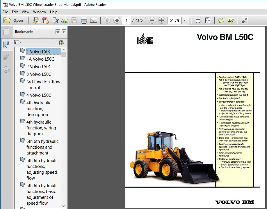
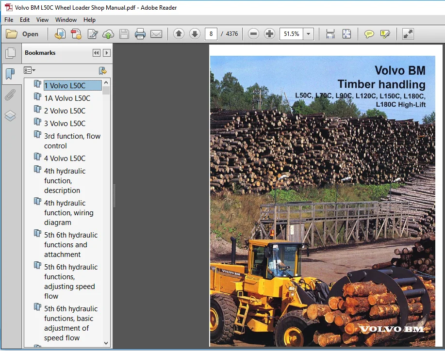
The strength and speed of Volvo BM wheel loaders is the result of an in-house manufactured drive train, composed entirely of robust and compatible Volvo BM components and perfectly matched to the working hydraulics and lift-arm system. ’I‘P Linkage provides superior breakout. capacity and parallel linkage action throughout the lifting range. Thanks to high break- out force in the top position. Volvo BM loaders have no problem picking up logs from high timber trucks. Parallel lift-arm action facilitates stacking of lumber pallets and packages. Handling timber is a precision job. Vfith pilot-operated working hydraulics, it is possible to operate all movements simultaneously with fingertip control. The duty-proven reliable Automatic Power Shift system (APS ll) enables you to concentrate on driving. Productivity-enhaneing technology, long life and high availability have made Volvo BM wheel loaders synonymous with excellence in timber ltzutdling all over the world.
Volvo BM Gare Cab protects the machine’s most important component :
The Volvo BM Care Cah is a protected and ergonomically designed workstation. t’ilowpcrated working hydraulics and a conveniently adjustable operator’s seat enable the openitor to work long shifts with high precision. The curved wind- shield without comer pillars and the large. well-situated glazed areas provide excellent all-round visibility. contribut- ing to safct}r 0n the workplace. Heavy insulation and rubber vibration isolatom tttalte the Volvo BM Care Cab quiet and vibration-free. The cah‘s climate control system supplies tempered, filtered flesh ainAir conditioning is available as an option.
TABLE OF CONTENTS:
Volvo BM L50C Wheel Loader Shop Manual
1 Volvo L50C....................................................................................   1
1A Volvo L50C...................................................................................   8
2 Volvo L50C....................................................................................  15
3 Volvo L50C....................................................................................  36
3rd function, flow control......................................................................  45
4 Volvo L50C....................................................................................  46
4th hydraulic function, description.............................................................  53
4th hydraulic function, wiring diagram..........................................................  54
5th 6th hydraulic functions and attachment......................................................  55
5th 6th hydraulic functions, adjusting speed flow...............................................  56
5th 6th hydraulic functions, basic adjustment of speed flow.....................................  58
5th 6th hydraulic functions, description........................................................  60
5th 6th hydraulic functions, draining the quick-action couplings................................  61
5th 6th hydraulic functions, electrical functions...............................................  62
5th 6th hydraulic functions, monitoring function, checking......................................  64
5th 6th hydraulic functions, wiring diagram.....................................................  66
AC compressor, fill with oil....................................................................  68
AC SAFETY, description of function..............................................................  69
Accumulator, Boom Suspension System,............................................................  70
Action for reducing risk of fire................................................................  72
Action to be taken in case of abnormal lubricating oil consumption..............................  74
Adjusting axial clearance on loader unit........................................................  78
Air cleaner, specifications.....................................................................  80
Air-suspended operator seat, ISRI...............................................................  81
Alternative lubricants for axles with wet brakes................................................  83
Amendments in Service Manual Engine, D10B; Drive Axle, AWB 40B and Drive Axle, AWB 41 AWB 50....  84
Attachment hydraulics GP, description...........................................................  85
Attachment hydraulics GP, wiring diagram........................................................  87
Attachment locking..............................................................................  88
Automatic greasing systems of foreign manufacture...............................................  98
Automatic transmission lubricants...............................................................  99
Axle suspension, checking axial and radial clearance............................................ 101
Axle, installing................................................................................ 103
Axle, removing.................................................................................. 105
Battery and alternator test procedure........................................................... 108
Battery, charging............................................................................... 110
Biodegradable hydraulic fluids.................................................................. 111
Boom Suspension System, description............................................................. 114
Boom Suspension System, hydraulic diagram....................................................... 118
Boom Suspension System, safety valve, checking, adjusting....................................... 120
Boom Suspension System, wiring diagram.......................................................... 123
Brake discs, checking wear (with built-in wear indicator)....................................... 124
Brake discs, checking wear (without built-in wear indicator).................................... 126
Brake discs, replacing.......................................................................... 128
Brake system, checking and adjusting pressure in circuit........................................ 135
Brakes.......................................................................................... 137
Capacities and weights.......................................................................... 138
Capacities and weights1......................................................................... 139
Care Track...................................................................................... 140
Change in tightening torque, AWB10.............................................................. 146
Checking speed with multimeter.................................................................. 147
Cleaning of the machine......................................................................... 149
Cleanliness when working on hydraulic systems................................................... 151
Clutch shaft, high-gear......................................................................... 152
Clutch shaft, low-gear.......................................................................... 153
Code key for diodes............................................................................. 154
Codes used in wiring diagrams................................................................... 156
Coding ECU (Electronic Control Unit)............................................................ 164
Cold-starting control, specifications........................................................... 167
Control unit BCU................................................................................ 168
Control unit ECU................................................................................ 169
Control valve, description...................................................................... 171
DEF AdBlue AUS32 sampling, method............................................................... 184
Description of function......................................................................... 187
Description..................................................................................... 188
	Description1................................................................................ 188
	Description2................................................................................ 192
	Description3................................................................................ 198
	Description4................................................................................ 200
	Description5................................................................................ 201
	Description6................................................................................ 202
	Description7................................................................................ 204
	Description8................................................................................ 207
Detecting leaks with inspection lamp............................................................ 208
Diesel test standards........................................................................... 209
Differential carrier assembly, front axle....................................................... 212
Discontinued recommendation for usage of anti-corrosion agent in cooling system................. 213
E 1664 Lifting tool............................................................................. 214
E 1666 Spanner.................................................................................. 215
E1752 Lifting yoke.............................................................................. 216
ECU, functional check........................................................................... 217
Electric welding................................................................................ 222
Electrical distribution box..................................................................... 223
Electrical system, description of function...................................................... 226
Engine, fitting................................................................................. 228
Engine, removing................................................................................ 230
Engine.......................................................................................... 237
E-tools......................................................................................... 240
Explanations of wiring diagrams,................................................................ 241
Feed pump, checking feed pressure TD40KAE....................................................... 243
Fender.......................................................................................... 245
Flow control for 3rd hydraulic function......................................................... 247
Fluid levels.................................................................................... 254
Foot brake valve (removed), reconditioning...................................................... 255
Foot brake valve, description of function....................................................... 258
Fork arms, information warranty matters, altered procedures..................................... 259
Frame joint bearing, lower, sectional view...................................................... 261
Frame joint bearing, upper, sectional view...................................................... 262
Frame joint, replacing bearings................................................................. 263
Fuel sampling, method........................................................................... 283
Fuel system, air bleeding TD40 KAE, TD40 GFE.................................................... 286
Fuel system, air bleeding TD40GA................................................................ 287
Fuel tank and combined tank unit, changing...................................................... 288
Fuel tank, specifications....................................................................... 291
Functional check................................................................................ 292
Gearbox, checking oil pressure.................................................................. 297
Gearbox, installing............................................................................. 299
Gearbox, removing............................................................................... 305
Gearbox, sectional view......................................................................... 312
General description............................................................................. 313
General description1............................................................................ 314
GRD G700B LabourTimeGuide Old version........................................................... 315
	G700B Labour Time Guide Foreword.pdf........................................................ 317
		Foreword, Labour Time Guide............................................................. 317
			The standard times are issued for the purpose of:................................... 317
			The following is not included in the listed times:.................................. 317
Greasing of hydraulic pump drive shaft.......................................................... 417
Headlights, adjusting........................................................................... 418
Hit Belt1....................................................................................... 419
Hit Belt2....................................................................................... 423
Hydraulic diagram basic machine, 3rd 4th,....................................................... 426
Hydraulic diagram basic machine, 3rd4th,........................................................ 428
Hydraulic diagram, basic machine................................................................ 430
Hydraulic diagram, brake system................................................................. 432
Hydraulic diagram, lever steering CDC Basic Machine............................................. 434
Hydraulic diagram, steering system Basic Machine................................................ 436
Hydraulic oil pump, removing and fitting........................................................ 437
Hydraulic pump, description..................................................................... 439
Hydraulic system................................................................................ 441
Hydrostatic pump, removing and fitting.......................................................... 442
Hydrostatic system, checking oil pressure....................................................... 446
Hydrostatic system, neutral position............................................................ 450
Improved securement for cab filter primary filter............................................... 455
Injection pump, fitting and adjusting injection timing, TD40KAE................................. 457
Injection pump, fitting, TD40GFE................................................................ 460
Injection pump, removing TD40GFE................................................................ 464
Injection pump, removing, TD40KAE............................................................... 468
Injection pump, specifications.................................................................. 471
Injection timing adjustment at low engine temp., TD40GFE........................................ 472
Injection timing, checking and adjusting, TD40GA................................................ 474
Injection timing, checking and adjusting, TD40KAE............................................... 475
Injectors and delivery pipes, specifications.................................................... 478
Installation kit for Operators seat1............................................................ 479
Installation kit for Operators seat2............................................................ 483
Instructions for crack in lifting frame......................................................... 489
Instructions for shielded metal arc welding..................................................... 491
Instruments and controls........................................................................ 494
Intercooler, specifications..................................................................... 496
Kit for fitting the radio....................................................................... 497
Lifting arm, replacing bearings A............................................................... 508
Lifting cylinder, replacing..................................................................... 512
Lifting cylinder, sectional view................................................................ 515
Lifting frame, replacing bearings B............................................................. 516
Limp-Home operation, by-passing control units................................................... 521
Lock cylinder for attachment bracket............................................................ 522
Low and high idling speed, checking and adjusting............................................... 523
Menu overview, service display unit............................................................. 525
Monitored functions ECU......................................................................... 526
MS.Internal.Documents........................................................................... 528
New TechTool VCADS Pro interface................................................................ 534
New warranty routines for Bosch diesel equipment................................................ 536
Non - VCE buckets and attachments............................................................... 538
Obligatory measures when repairing the hydrostatic system....................................... 539
Oil analyses.................................................................................... 542
Oil sampling, method............................................................................ 545
Oils for Volvos wheel loaders equipped with AWB axles (Axle Wet Brakes)......................... 552
Other electrical functions controlled by the control unit, ECU.................................. 554
Paper sintered type brake disc and mechanical wear indicator.................................... 555
Parking brake, adjusting........................................................................ 576
Planetary gear.................................................................................. 578
Plugs and restrictors in control valve.......................................................... 579
Portable refillable O-ring kits................................................................. 583
Power transmission.............................................................................. 584
Pressure drop in hydrostatic circuit............................................................ 585
Product identification plates................................................................... 587
Production development list for Volvo BM transmissions.......................................... 588
Protecting grating.............................................................................. 601
Quality of illustrations in technical reports................................................... 603
Raising and supporting machines (up to and including the E models).............................. 606
Rear axle suspension............................................................................ 611
Recommendations for Oil Sampling Intervals...................................................... 612
Recovering reclaiming refrigerant R134a using recovery unit FRS-10 GS........................... 614
Reinforcing lifting frame B-arm attachment (service solution)................................... 635
Repair instructions for attachments............................................................. 637
Repairing hydraulic system...................................................................... 639
Replacing brake discs........................................................................... 640
Replacing operator seat shock absorber.......................................................... 644
Reporting of product misuse & near-miss report.................................................. 646
Reports......................................................................................... 649
Retardation, functional check................................................................... 651
RM Compaction ABG Time Guide Old................................................................ 653
	Foreword.................................................................................... 653
	Drum........................................................................................ 654
	Hydraulic................................................................................... 655
	Electrical.................................................................................. 656
	Engine...................................................................................... 657
	Structural.................................................................................. 658
	Drive system................................................................................ 659
	Water....................................................................................... 660
RM Compaction Time guide old version............................................................ 661
	Drum........................................................................................ 662
	Hydraulic................................................................................... 666
	Electrical.................................................................................. 670
	Engine...................................................................................... 674
	Structural.................................................................................. 678
	Drive system................................................................................ 686
	Water....................................................................................... 690
RM Paving Systems ABG Time Guide Old............................................................ 692
	Foreword.................................................................................... 692
	Screeds..................................................................................... 693
	Hydraulics.................................................................................. 694
	Structural.................................................................................. 696
	Engine...................................................................................... 697
	Drive system................................................................................ 698
	Electrical.................................................................................. 699
Rotating beacon................................................................................. 700
Seals........................................................................................... 702
Secondary steering Introduction of non-return valve............................................. 703
Service display unit............................................................................ 704
Service solution for loader unit, improved D-pin locking........................................ 711
Servo pressure, checking and adjusting.......................................................... 712
Servo valve, description........................................................................ 713
Servo valve, single control lever............................................................... 715
Shock valve, lifting function, checking and adjusting........................................... 720
Shock valve, tilting function, checking and adjusting........................................... 723
Software in E-ECU for engines supplied as spare part............................................ 727
Special instructions when working on the electrical system...................................... 728
Special tool catalog............................................................................ 729
	General..................................................................................... 729
	Index ...................................................................................... 731
	Hooks....................................................................................... 743
	1. Enviroment and Safety equipment ......................................................... 755
	2. Measuring equipment...................................................................... 787
	3. Tightening and Loosening tools........................................................... 889
	4. Lifting equipment........................................................................ 935
	5. Pullers and Pressing equipment........................................................... 959
	6. Drifts...................................................................................1041
	7. Guide pins and Guide sleeves.............................................................1167
	8. Pliers...................................................................................1237
	9. Fixtures.................................................................................1249
	10. Tech Tool...............................................................................1269
	11. Spare parts.............................................................................1279
Special Tools Recommendations...................................................................1303
Specifications, coolant pump and thermostat.....................................................1304
Specifications..................................................................................1305
	Specifications1.............................................................................1305
	Specifications2.............................................................................1306
	Specifications3.............................................................................1307
	Specifications4.............................................................................1308
	Specifications5.............................................................................1309
	Specifications6.............................................................................1310
	Specifications7.............................................................................1311
	Specifications8.............................................................................1312
	Specifications9.............................................................................1313
	Specifications10............................................................................1314
Standard tightening torques.....................................................................1316
Standard tightening torques1....................................................................1317
Stand-by pressure, checking and adjusting.......................................................1318
Steering cylinder, reconditioning...............................................................1320
Steering cylinder, replacing....................................................................1323
Steering cylinder, sectional view...............................................................1327
Steering pressure and stand-by pressure, checking and adjusting.................................1328
Steering valve, description.....................................................................1331
Steering valve, reconditioning..................................................................1335
Steering........................................................................................1343
T link, upper, removed, replacing bearings HIJ..................................................1344
Tightening torques..............................................................................1350
Tightening torques1.............................................................................1352
Tilting and lifting cylinders...................................................................1354
Tilting arm, replacing bearings GDF.............................................................1356
Tilting cylinder, replacing.....................................................................1361
Tilting cylinder, sectional view................................................................1365
Time Guide Currrent generation..................................................................1366
Time Guide Old generation.......................................................................2542
Time Guide Previous generation..................................................................3370
Time Guide......................................................................................4160
T-link, lower, removed, replacing bearings GH...................................................4168
Tool box........................................................................................4172
Towing..........................................................................................4174
Transporting a wheel loader on another vehicle..................................................4176
Turbocharger, specifications....................................................................4177
Tyres, various types............................................................................4178
Units connected to control unit BCU.............................................................4180
Units connected to control unit ECU.............................................................4181
Valve adjustment................................................................................4183
Valves, adjusting...............................................................................4185
Ventilation servo casing........................................................................4187
Volvo Product incident accident report & Interview Form.........................................4190
Water separator improvement.....................................................................4193
Windshield washer...............................................................................4196
Wiring diag. 22D. 4th hydr. fctn., actvt. thru. brake press. chg. attachm. locking brake........4207
Wiring diagram 1. Main diagram BCU..............................................................4210
Wiring diagram 1B. Main diagram ECU.............................................................4213
Wiring diagram 1C. Main diagram Limp-Home operation ECU.........................................4216
Wiring diagram 2. BCU...........................................................................4219
Wiring diagram 2. BCU1..........................................................................4222
Wiring diagram 2D. Intermittent wiper BCU.......................................................4225
Wiring diagram 3. Gear shifting BCU.............................................................4227
Wiring diagram 3B. Gear shifting ECU............................................................4230
Wiring diagram 3C. Limp-Home opn. ECU...........................................................4233
Wiring diagram 4. Gear shift solenoids ECU......................................................4236
Wiring diagram 5. Engine TD40GA, TD40GFE........................................................4238
Wiring diagram 5D. Engine TD40KAE...............................................................4241
Wiring diagram 5D. Preheating engine TD40KAE. W.e.fr. serial number 11233.......................4244
Wiring diagram 6. Hydraulics....................................................................4247
Wiring diagram 6B. Single lever ctrl. w. boom kick-out and bucket pos...........................4250
Wiring diagram 7B. Secondary steering ECU.......................................................4253
Wiring diagram 7C. Secondary steering with ECU by-passed........................................4256
Wiring diagram 8. Pressure draining, brake pressure charging,...................................4259
Wiring diagram 8D. Brake pressure charging, attachment locking..................................4262
Wiring diagram 9. Travel lights.................................................................4265
Wiring diagram 10. Working lights, rotating warning beacon......................................4268
Wiring diagram 11. Stop lights, direction indicators, hazard flashers...........................4271
Wiring diagram 12. Radio, heated seat...........................................................4274
Wiring diagram 13. Instruments, sensors BCU.....................................................4277
Wiring diagram 13B. Instr, sensors ECU..........................................................4280
Wiring diagram 13C. Instruments, sensors ECU during Limp-Home operation.........................4283
Wiring diagram 14. Instr., alternator BCU.......................................................4286
Wiring diagram 14B. Instr., alternator ECU......................................................4289
Wiring diagram 14C. Instruments, alternator ECU during Limp-Home operation......................4292
Wiring diagram 15. Dual control Forward Reverse BCU.............................................4295
Wiring diagram 15B. Dual control Forward Reverse ECU............................................4298
Wiring diagram 15C. Dual control Forward Reverse during Limp-Home operation ECU.................4301
Wiring diagram 15D. Single lever control........................................................4304
Wiring diagram 16. Air conditioning (AC)........................................................4307
Wiring diagram 17. Service display unit.........................................................4310
Wiring diagram 18. Boom Susp. System (BSS)......................................................4313
Wiring diagram 19. Mechanical parking brake with Rider truck safety norm........................4316
Wiring diagram 19D. Hydraulic parking brake.....................................................4319
Wiring diagram 20B. Lever steering (CDC) w. adjust. ramp gen. Up to and incl. sn 10631..........4321
Wiring diagram 20B. Lever steering (CDC) w. non-adjust ramp gen. W.e.fr.........................4324
Wiring diagram 21. 4th hydraulic function, activation...........................................4327
Wiring diagram 21. 4th hydraulic function, activation1..........................................4329
Wiring diagram 21D. 4th hydraulic function, activation..........................................4331
Wiring diagram 21D. 4th hydraulic function, activation1.........................................4333
Wiring diagram 22. 4th hydraulic function,......................................................4335
Wiring diagram 22. 4th hydraulic function,1.....................................................4338
Wiring diagram 23. 3rd hydraulic function.......................................................4341
Wiring diagram 23. 3rd hydraulic function1......................................................4344
Wiring diagram 25. 5th and 6th hydr. function...................................................4347
Wiring diagram 25. 5th and 6th hydr. function1..................................................4350
Wiring diagram 26. Automatic greasing...........................................................4353
Wiring diagram 27. Automatic greasing with......................................................4356
Wiring diagram 28. Mechanical and hydraulic.....................................................4359
Wiring diagram 28B. Mechanical and hydraulic parking brake with ECU.............................4362
Work light1.....................................................................................4365
Work light2.....................................................................................4368
Working hydraulics, description.................................................................4371
Working pressure, checking and adjusting........................................................4375
PLEASE NOTE:
- This is the same manual used by the dealers to diagnose and troubleshoot your vehicle
- You will be directed to the download page as soon as the purchase is completed. The whole payment and downloading process will take anywhere between 2-5 minutes
- Need any other service / repair / parts manual, please feel free to contact [email protected] . We still have 50,000 manuals unlisted

Leroy Jon –