
Volvo EC240B EC290B Technical Training Manual – Engine, Transmission & Hydraulics PDF
Original price was: $52.95.$34.95Current price is: $34.95.
Complete Volvo EC240B and EC290B excavator technical training manual covering the D7D engine, transmission, hydraulics, electronics, and air conditioning systems. Instant PDF download.
Description
Volvo EC240B & EC290B Technical Training Manual
This Volvo EC240B EC290B technical training manual provides comprehensive coverage of the engine, transmission, hydraulics, and electronic control systems used in these Volvo excavators. Originally developed for Volvo Construction Equipment customer support and dealer training, it walks through the D7D engine platform, the hydraulic pump and main control valve systems, travel and swing motors, and the complete electronic control architecture including the E-ECU, V-ECU, and I-ECU. The manual is intended for technicians, mechanics, and service personnel who need to understand how these systems operate, how they are controlled, and how to diagnose and repair them correctly.
File Details
- Manual type: Technical Training Material
- Brand: Volvo Construction Equipment
- Models covered: EC240B, EC290B
- Engine series: D7D (D70 EAE2, D70 EBE2)
- Language: English
- Page count: 225
- File format: PDF
Chapters Covered
- Engine Specification and Components
- Cylinder Head, Valves, Liner and Piston
- Camshaft, Crankshaft, and Timing Gears
- Lubrication System
- Fuel System
- Cooling System
- Engine Control System
- Electronic Control System Overview
- V-ECU Input and Output
- Engine Speed and Work Mode Control
- Safe Start and Stop Control
- Machine Status Indication and System Diagnosis
- Electrical Components and Circuits
- Air Conditioning System
- Hydraulic System
- Hydraulic Pump and Regulator
- Main Control Valve and Relief Valves
- Servo System and Joystick
- Power Transmission – Swing and Travel Motors
- Cylinders and Turning Joint
- EC290B Update – New I-ECU
Engine Specification and Components
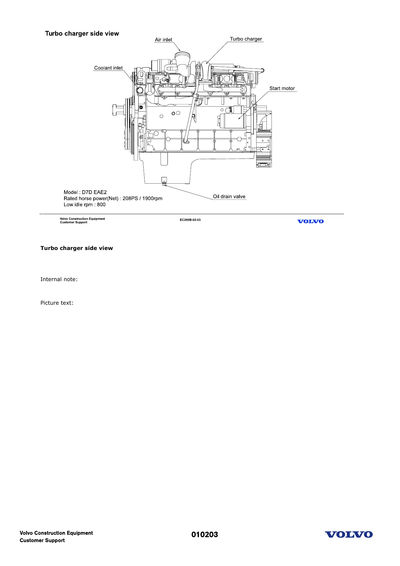
The manual opens with a full engine specification table comparing the EC290B and EC240B powerplants, followed by detailed views of the D7D engine from every angle. You get the turbocharger side view, fuel injection pump side view, top view, fan side view, and flywheel side view, each with labelled components. Engine mounting details include the colour-coded cushion installation for fan side and flywheel side. The cylinder head section explains the grey cast iron block-type design, combustion air entry, and exhaust discharge routing. Valve specifications cover inlet and exhaust seat angles (30° and 45°), valve guide O-rings, and the single-type valve springs.
Cylinder Head, Valves, Liner and Piston
Detailed coverage of the wet replaceable cylinder liners with their two O-ring grooves, the three-ring piston assembly (keystone first ring, conical compression second ring, and bevelled-edge oil control ring), and piston cooling. The piston and connecting rod section explains the eccentric piston bowl, flywheel marking orientation, locating lugs, and centring pins. Critical reuse specifications are included: big end bearing cap screws can be reused twice, and flywheel bolts may be used five times. Head gasket selection is covered with the piston projection measurement chart and the corresponding number of holes on the gasket.
Camshaft, Crankshaft, and Timing Gears
The camshaft runs on seven bearings with induction-hardened running surfaces and is driven by the timing gears at the flywheel end. The forged crankshaft has seven main bearings, with the second bearing acting as the thrust bearing, and carries integrated balance weights. Two hydraulic-type torsional vibration dampers are described in detail, including how the silicon oil equalises pulsing rotation. Timing gear alignment markings on the crankshaft flange and camshaft gear are explained with the note about the imaginary centre line between the two gears.
Lubrication and Fuel Systems
The lubrication system section covers the forced-feed circulation circuit with oil cooler and full-flow filter. Components include the oil pressure relief valve (opening at 4 ± 0.5 bar), safety valve (opening at 10 ± 1 bar), tappet pulse lubrication, rocker arm oil supply, and piston cooling spray nozzles. The fuel system chapter explains the direct injection principle with single injection pumps integrated into the cylinder block and driven by the engine camshaft. Maximum injection pressure reaches up to 1500 bar, with injector opening pressure at 255 bar. The rotary fuel pump is V-belt driven and includes a two-way valve, overpressure relief valve (6 ± 0.5 bar), and a hand pump for bleeding the system.
Cooling System and Air Management
The closed-circuit cooling system with forced circulation is detailed, including the belt-driven coolant pump, thermostat operation (start to open at 83°C, fully open at 95°C), and the coolant flow path through the oil cooler, cylinder liners, cylinder head, and radiator. The blowby gas return system routes crankcase gases back to the intake port rather than to atmosphere. The charged air cooler (CAC) section covers the drain cock for removing accumulated contaminants.
Engine Control System
The EMS (Engine Management System) with E-ECU is covered in depth, including all sensor inputs: engine speed (crank and cam), boost pressure, boost temperature, coolant temperature, fuel temperature, oil pressure, inlet air pressure and temperature, coolant level, and emergency switch. The injection control principle explains how ambient pressure, turbocharger boost, and temperature affect fuel quantity and injection timing. The speed sensor failure section describes how the E-ECU compensates and what happens when the cam speed sensor fails. Cylinder balance monitoring through flywheel speed sensing is also explained. The preheat function is documented with pre-heating and after-heating time diagrams for different coolant temperatures.
Electronic Control System Overview
The electronic control architecture comprises the E-ECU (MID 128), V-ECU (MID 187), and MDU (MID 140), communicating over CAN bus (SAE J1939) and Information bus (SAE J1708). The manual explains MID, PID, PPID, SID, and PSID identification numbers. V-ECU input and output signals are fully mapped, including the functions it controls: self-diagnosis, machine status indication, mode selection, Engine Speed Sensing Power Control (ESSPC), automatic return to idle, automatic and one-touch power boost, safe start and stop, automatic travel speed control, emergency control (limp home mode), and pump flow control for optional equipment (X1).
Work Mode and Engine Speed Control
The manual covers the 10-step engine speed and 5 work-mode control system. The power shift valve operation is explained with the current and pressure specifications for each mode (I, F, P, H, G) across the USA and other markets. F-mode operation is detailed, including travel speed lock, power boost activation, and boom-arm conflux cutoff. Auto-return to idle is described with the default 5-second delay and adjustable 3 to 10-second range via VCADS Pro. Safe start and stop control protects the engine during starting and shutdown.
Machine Status and Diagnosis
The Machine Display Unit (MDU) and instrument panel are covered with their display modes and indicator operations. System diagnosis describes how error codes are displayed and what each indicator means, including the error code tables for V-ECU and E-ECU. The operating data memory section lists all 32 data parameters saved for MATRIS analysis. Pump flow control for optional attachments is explained with the flow control switch and proportional valve operation.
Electrical Components and Circuits
This section covers the engine start and stop circuit, master switch, key switch, battery relay, safety start relay with its restart protection and start interlock functions, safety limit switch, alternator, slow blow fuses, fuse box, instrument panel circuit, and individual sensors and switches. Each component’s operation is explained with circuit diagrams and testing procedures. The switch circuit section provides continuity test diagrams for all panel switches.
Air Conditioning System
The air conditioning system overview covers the combined heating and cooling unit, ambient and main filters, mix door operation, blower motor, evaporator, expansion valve, condenser, receiver drier, compressor, and diesel heater option. The automatic control system input-output diagram shows all sensors and actuators. Error codes (E1 through E6) for the air conditioning system are listed with their causes. Compressor and mix door control specifications are given for each switch step, along with mode door and intake door control tables. The compressor specifications include refrigerant type (R-134a), displacement (154.9 cc/rev), and oil type (SP-10 or equivalent, 240cc charge).
Hydraulic System
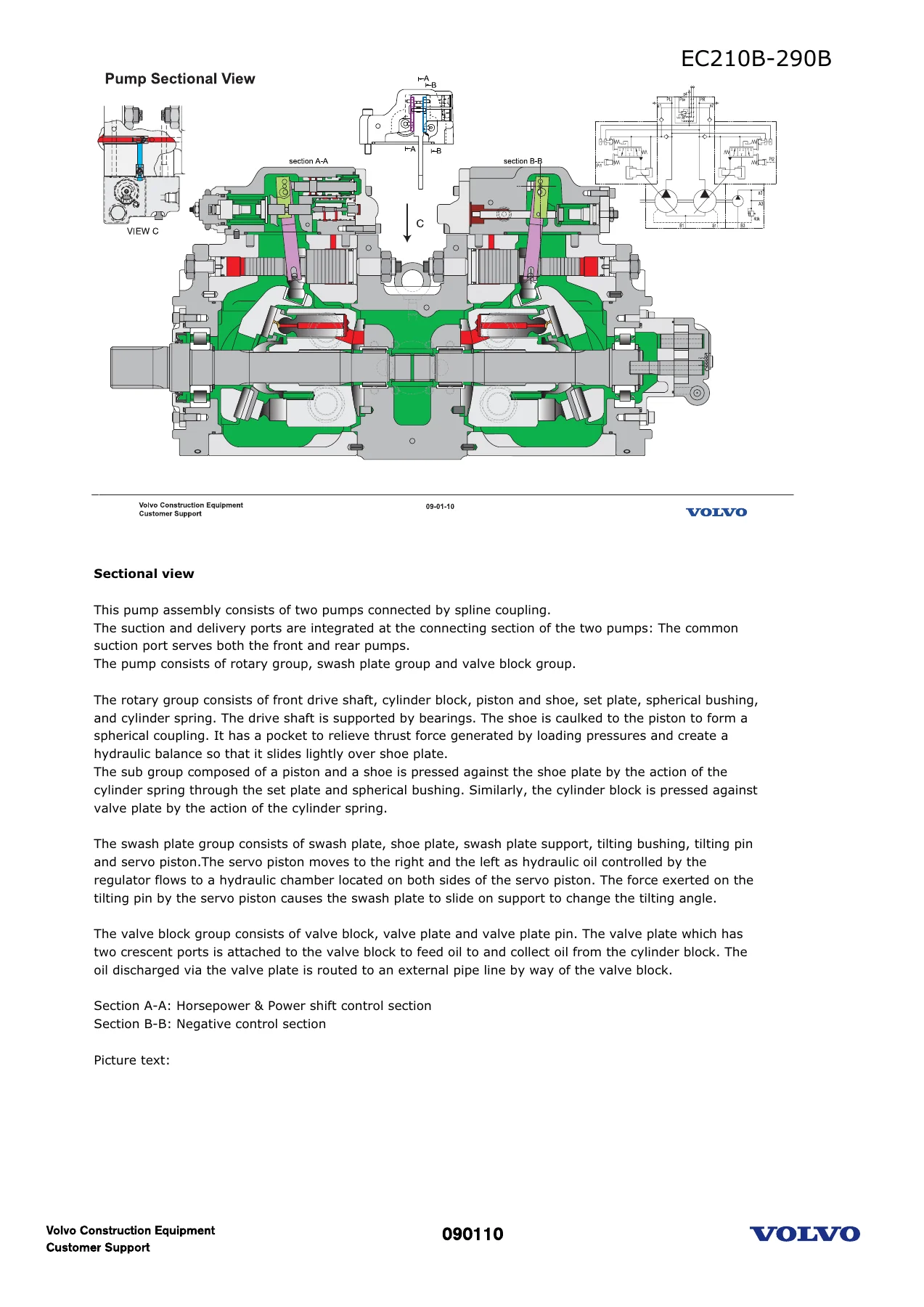
The hydraulic system overview explains how mechanical power from the engine is converted to hydraulic power by two variable displacement piston pumps, plus two fixed gear pumps for the servo system and X3. The manual covers the full-option hydraulic circuit, basic machine circuit, and brief circuits for main and pilot systems. The hydraulic pump section details the K3V112DT-1XJR-9N2D-V (EC240B) and K3V140DT-151R-9NE9-HV (EC290B) piston pumps with sectional views, regulator operation, and P-Q curves. The main control valve, main relief valve operation and adjustment, port relief valve operation, 2-stage port relief valve operation and adjustment, flow sensing valve, and various spool operations are all documented.
Servo System and Control Components
The servo system layout covers the pilot filter, accumulator block, solenoid blocks, shuttle blocks, pilot block, and the flow control valve on the arm spool pilot line. Joystick operation, travel pedal operation, and their characteristic curves are explained. The solenoid valve block functions include safety solenoid, 1 or 2 pump select solenoid, power boost solenoid, travel speed solenoid, hammer solenoid, and boom & arm conflux cutoff solenoid. Shock reducing valves, shuttle valve block, and pilot block are also covered.
Power Transmission
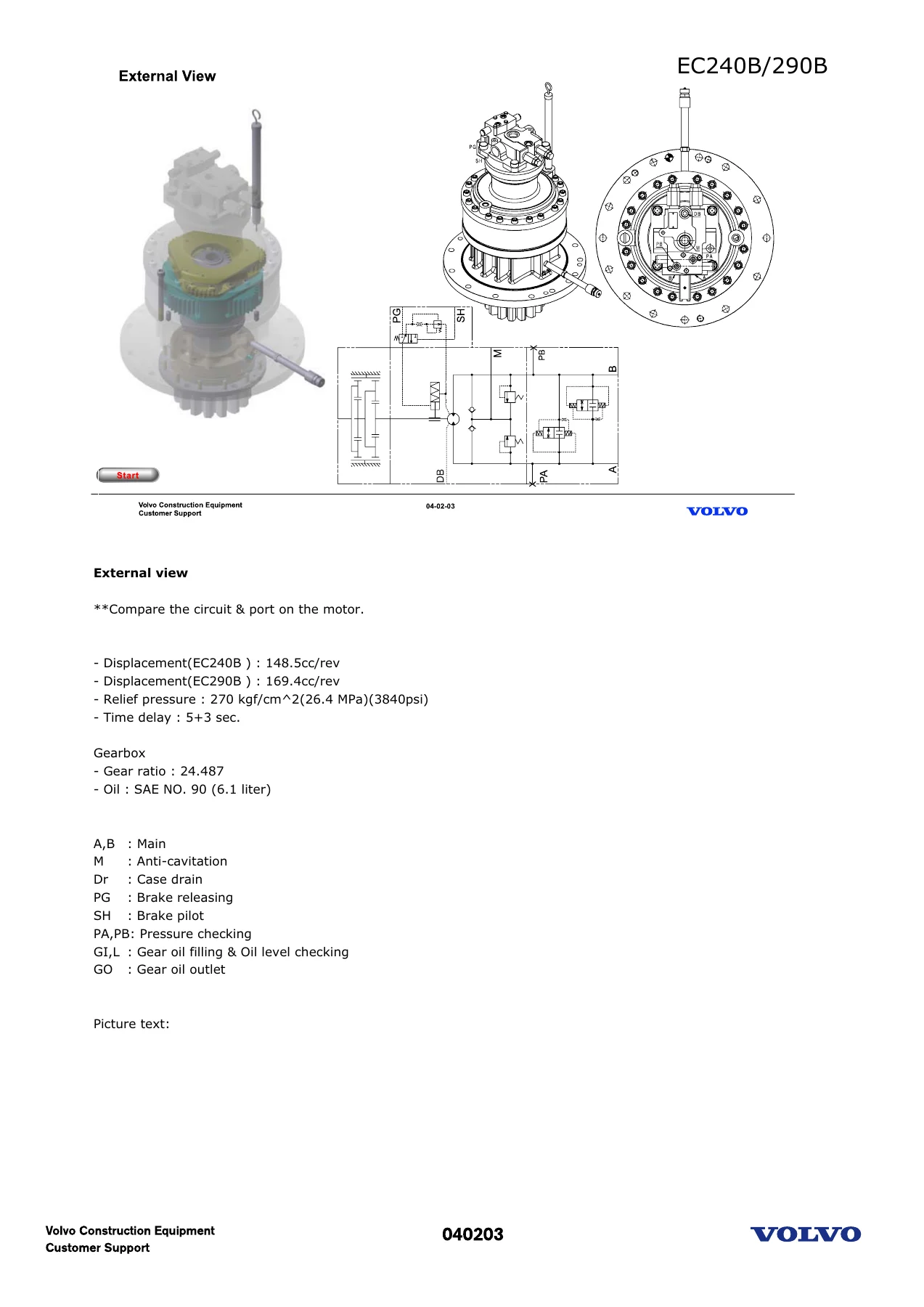
The swing motor section covers the EC210B, EC240B, and EC290B variants with displacement, relief pressure, and time delay specifications. Sectional views show the rotary group, valve plate, mechanical parking brake, relief valve, anti-cavitation valve, and rebound damping valve. The parking brake operation includes the 5-second time delay function. The travel motor section covers the EM140V and EC290B travel motors with displacement, relief pressure, speed changeover pressure, and gear ratio specifications. Brake valve operation, speed changeover, and reducing valve operation are explained with sectional views.
Cylinders and Turning Joint
The cylinder section identifies all components: piston, tube, rod, gland, cushion ring, cushion plunger, dust wiper, rod packing, buffer ring, dry bearing, contamination seal, wear ring, and piston packing. The turning joint section explains how high-pressure oil from the main control valve is delivered to the left and right track motors through ports C-E or D-F, with drain oil returning via port G and track high-speed control servo oil entering port B. The hub is fixed to the lower frame while the shaft rotates on the superstructure, with circumferential grooves allowing oil flow during slew. Return check valves (3k and 4.5k) and the hydraulic oil cooling system are also covered.
EC290B Update – New I-ECU
The final chapters cover the EC290B update introducing the new I-ECU for commonality, with machine serial number ranges (CHW 12508~ and SHA 30178~). Changes include integration of hardware, relocation of switches (A/C switch to RH control box, emergency/auto-manual/1-2 pump select to LH control box, hour meter to LH control box), and flow setting now done at the I-ECU instead of a flow control switch. The new I-ECU circuit uses a 10-pin connector and communicates via the CAN and information buses. Power on-off procedures, buzzer sound specifications, code lock operation, and error message tables for ECU, communication, electric system, hydraulic system, and engine are all documented. The alternator change and safety start relay change (with time delay function) are explained with old and new circuit diagrams.
Why This Manual Matters
Whether you are diagnosing an engine performance issue, rebuilding a hydraulic pump, troubleshooting an electronic control fault, or servicing the air conditioning system, this Volvo EC240B EC290B technical training manual provides the specifications, procedures, and system knowledge you need. The combination of detailed component illustrations, complete specification tables, and step-by-step operational explanations makes it an essential reference for any technician working on these machines.
IMAGES PREVIEW
Instant PDF Delivery
This Volvo EC240B EC290B engine, transmission and hydraulics manual is delivered as an instant PDF download after payment. No shipping, no waiting. You can view it on any device, print the pages you need for the workshop, and keep it as a permanent reference. Whether you are a professional technician, a fleet maintenance manager, or an owner-operator who does their own repairs, this manual gives you the information to get the job done correctly.
Reviews
There are no reviews yet.