
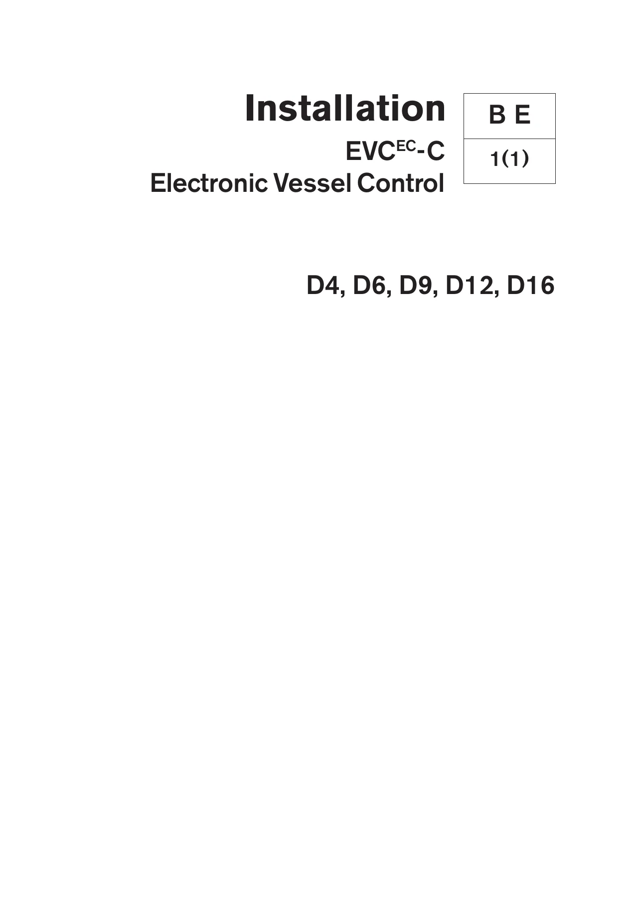
Volvo Penta D4 D6 D9 D12 D16 EVC-C Electronic Vessel Control Installation Manual
Original price was: $34.95.$19.95Current price is: $19.95.
Complete Volvo Penta EVC-C installation manual for D4, D6, D9, D12 and D16 engines. Covers PCU and HCU setup, harness routing, calibration, diagnostics, NMEA interfaces, Powertrim, Lowspeed/trolling and wiring schematics.
Description
Volvo Penta EVC-C Installation Manual for D4, D6, D9, D12 and D16 Engines
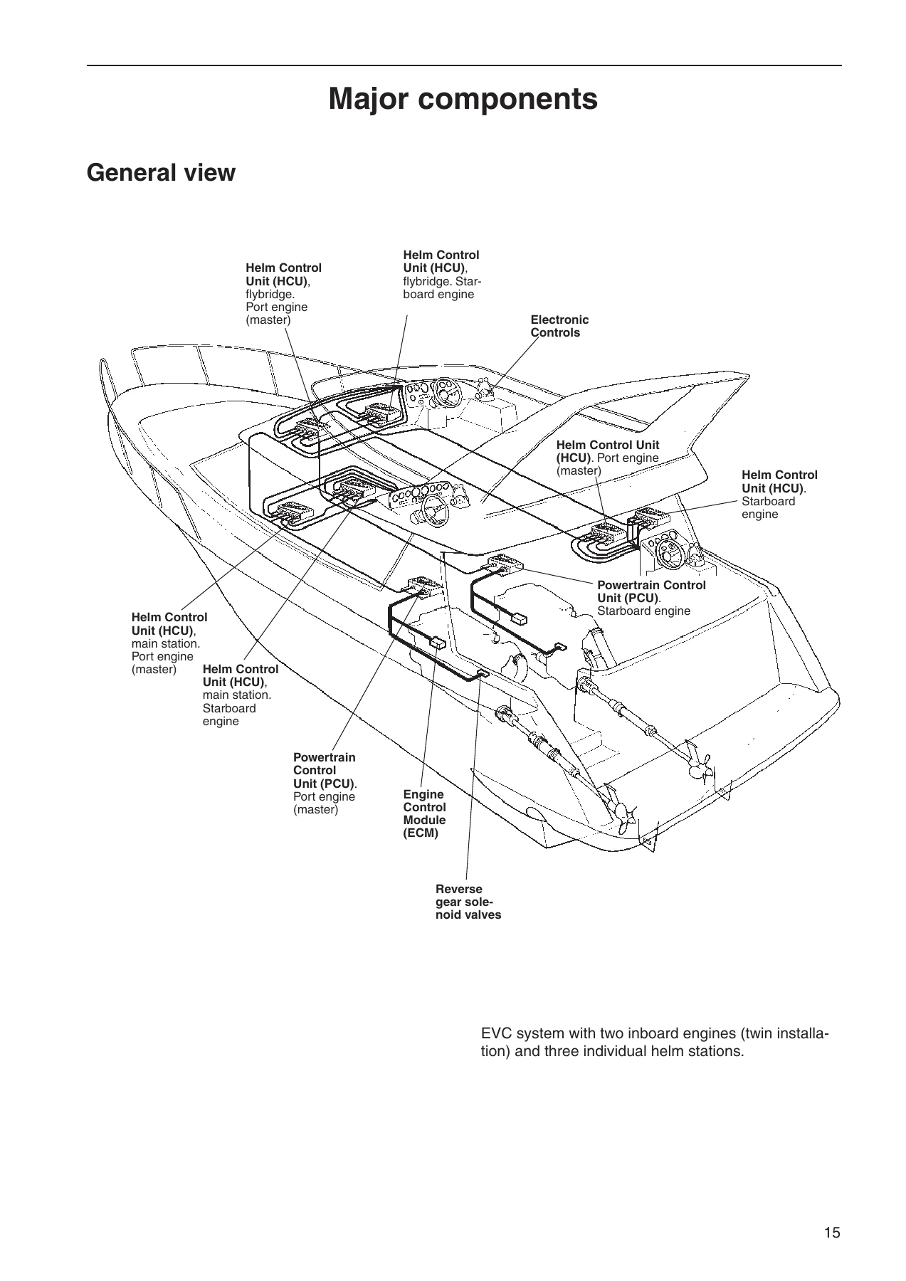
This Volvo Penta D4 D6 D9 D12 D16 EVC-C Electronic Vessel Control Installation Manual is the complete guide for professional installation, calibration and commissioning of the EVC-C electronic vessel control system across Volvo Penta’s diesel engine range. Whether you are fitting a new build, retrofitting an EVC system or reconfiguring an existing helm, this manual gives the installer the exact procedures, wiring schematics and calibration routines required to get the system running correctly from the first key turn.
File Details
- Manual type: Installation Manual
- Brand: Volvo Penta
- Models covered: D4, D6, D9, D12, D16
- System: EVC-C (Electronic Vessel Control)
- Applications: Aquamatic and inboard, DPH/DPR stern drives, Volvo Penta IPS
- Language: English
- Page count: 138
- File format: PDF
- Publication information shown: 2007 AB Volvo Penta
Chapters Covered
- Y-connector
- Key switch and relay
- Start/stop panel
- EVC control panel
- Powertrim panel
- Relay for external accessories
- Instruments
- Instrument, panels and auxiliary cable
- Buzzer
- Auxiliary dimmer unit (ADU)
- Synchronizing cable, twin installations
- EVC system display
- NMEA 0183 interface
- NMEA 2000 interface
- Multisensor
- Controls, electronic
- Adapter for mechanical controls
- Controls, mechanical
- Interface 4-20 mA
- EVC control panels
- Calibration and settings
- Calibration mode
- Auto configuration
- EVC control lever combinations
- Lever calibration
- Select language and units
- Powertrim calibration
- Powertrim Assistance (PTA)
- Trolling calibration
- Slip calibration
- Idling speed calibration
- OEM-mode
- Fuel tank settings
- Fuel tank calibration
- Multisensor calibration
- Diagnostic function
- Fault register
- Parameter settings
- Starting the engine
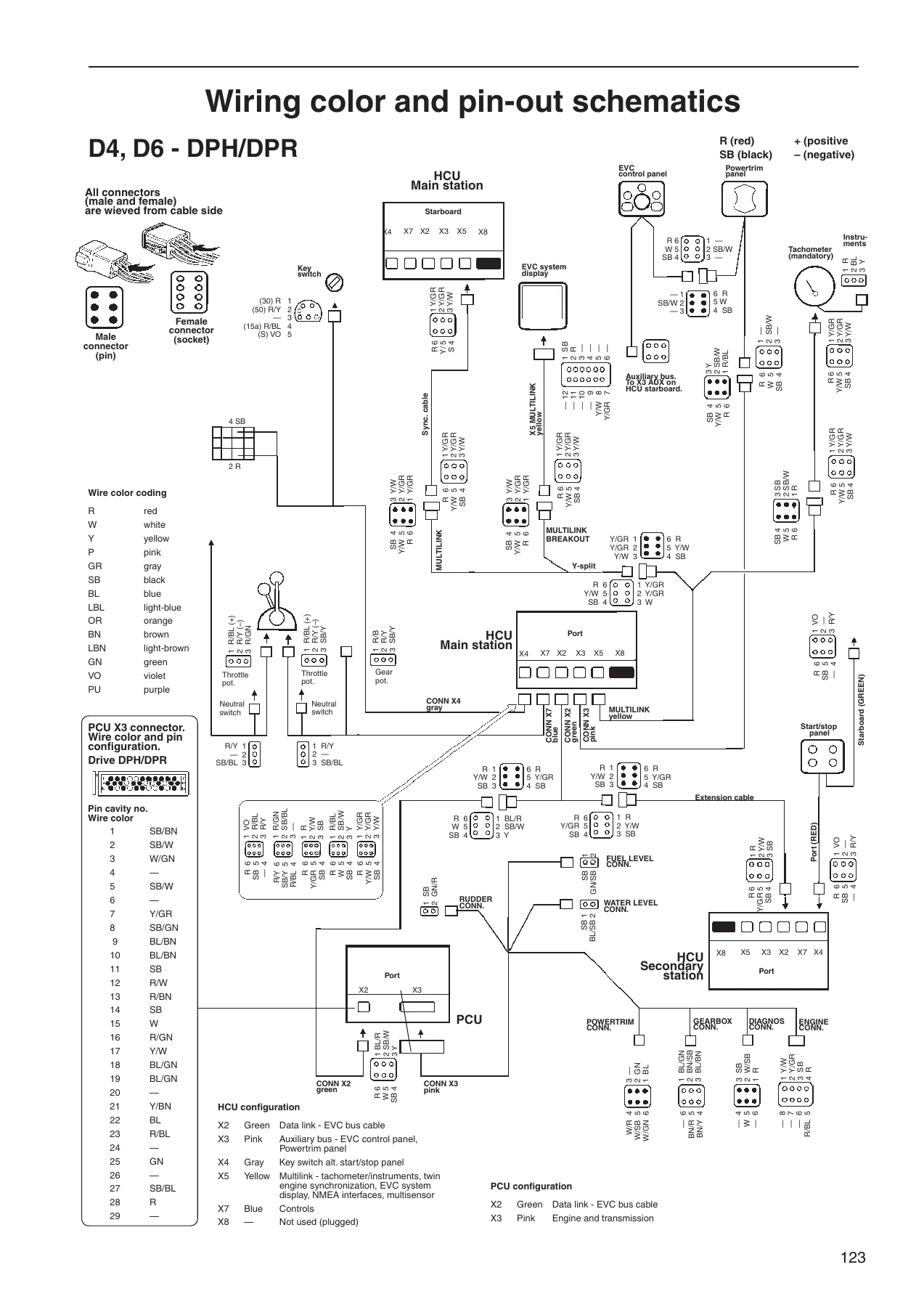
- Wiring color and pin-out schematics
- Templates for controls and panels
- References to Service bulletins
The manual opens with safety precautions and general information before moving through the EVC-C system architecture, node identification, cable harnesses, component mounting and connection. Detailed installation procedures are given for the engine room and helm, followed by full calibration, diagnostic and parameter setting routines. Wiring colour and pin-out schematics and printable templates for controls and panels complete the document.
Engine Room and Helm Installation
The installation section covers PCU and HCU location and mounting, engine-PCU cable connection for inboard and DPH/DPR sterndrive applications, transmission cable connection for HS45, HS63, HS80, HS85 and ZF reverse gears, propeller rotation checks, lowspeed and trolling slip valve fitment, rudder indicator fitting, fuel and fresh water level sender installation, and calibration. Helm installation covers Y-connector location, key switch and relay wiring, start/stop panels, EVC control panels, Powertrim panels, external accessory relays, instrument mounting, buzzer fitment, auxiliary dimmer unit, tachometer, synchronization cable and EVC system display connection.
Diagnostics, Fault Register and Parameter Settings
The diagnostic function chapter explains how the system monitors engine, sterndrive and EVC components, the reaction levels that reduce power or disengage gear, and how fault pop-ups and the fault register work. The fault register lists each alarm with its explanation, reaction and recommended action. Parameter settings cover Transfer Under Way, classified engine, Volvo Penta Lowspeed slip factors, neutral beep, transom angle and lever type adjustments via the VODIA diagnostic tool.
Wiring Schematics and Templates
Wiring colour and pin-out schematics are provided for D4/D6 with DPH/DPR and for D4, D6, D9, D12 and D16 installations, together with full colour-coding tables for the PCU X3 and HCU connectors. Templates for top-mounted controls, side-mounted controls and panels are included at scale, making it straightforward to mark out dashboards and bulkheads accurately.
What This Manual Enables
With this manual a qualified installer or professional boat electrician can mount, wire and configure the entire EVC-C system correctly the first time. It covers the full electrical architecture, node programming, harness routing, calibration routines and fault diagnostics, so problems can be identified and corrected without guesswork. Getting the calibration, auto configuration and lever setup right is what allows the engine to start and run correctly, so having the exact factory procedures matters.
IMAGES PREVIEW
Instant PDF Delivery
Delivered as an instant PDF download, no shipping and no waiting. Read it on any computer, tablet or phone, search and print the pages you need for the job at hand. Keep the file on the workshop laptop and reference the calibration screens, wiring schematics and templates whenever you need them. This Volvo Penta EVC-C installation manual for the D4, D6, D9, D12 and D16 engines is the practical reference you want when it matters.
Reviews
There are no reviews yet.