
Volvo Penta EVC 2 Electrical System Workshop Manual Group 30 – PDF
Original price was: $39.95.$24.95Current price is: $24.95.
Volvo Penta EVC 2 Workshop Manual Group 30 covering the complete electrical system: EVC nodes, CAN datalink networks, fault tracing and fault code tables for BCM, HCU, ICM, PCU, SCM, SUS, VMM and SCU, plus measurement procedures, DTC matrices and wiring diagram references.
Description
Volvo Penta EVC 2 Electrical System Workshop Manual Group 30
This is the Group 30 Electrical System volume of the Volvo Penta EVC 2 workshop manual, publication 47711763_US dated 03-2023. It is a dedicated electrical and electronic systems manual for boats running the EVC 2 distributed control platform, and it takes the reader from the general architecture of the system all the way through to individual fault code diagnosis at node level. Rather than a general engine service book, this volume concentrates entirely on the electrical network, the control units attached to it, the sensors and actuators they manage, and the diagnostic routines used to bring a faulty system back to specification.
File Details
- Manual type: Workshop manual, electrical system group
- Brand: Volvo Penta
- System: EVC 2 (Electronic Vessel Control, generation 2)
- Group: 30 – Electrical System
- Publication number: 47711763_US
- Edition / date: 03-2023
- Language: English
- Page count: 415 pages
- File format: PDF
Chapters Covered
- Safety Information
- Special Service Tools
- General EVC System – design and function, node identification, chassis ID labelling
- Repair Instructions – general advice on working with EVC engines, connector handling, main switch isolation
- Electrical Welding – disconnection sequence and earth clamp placement
- Lost e-Key for EVC2 – eKey list reset and re-registration procedure
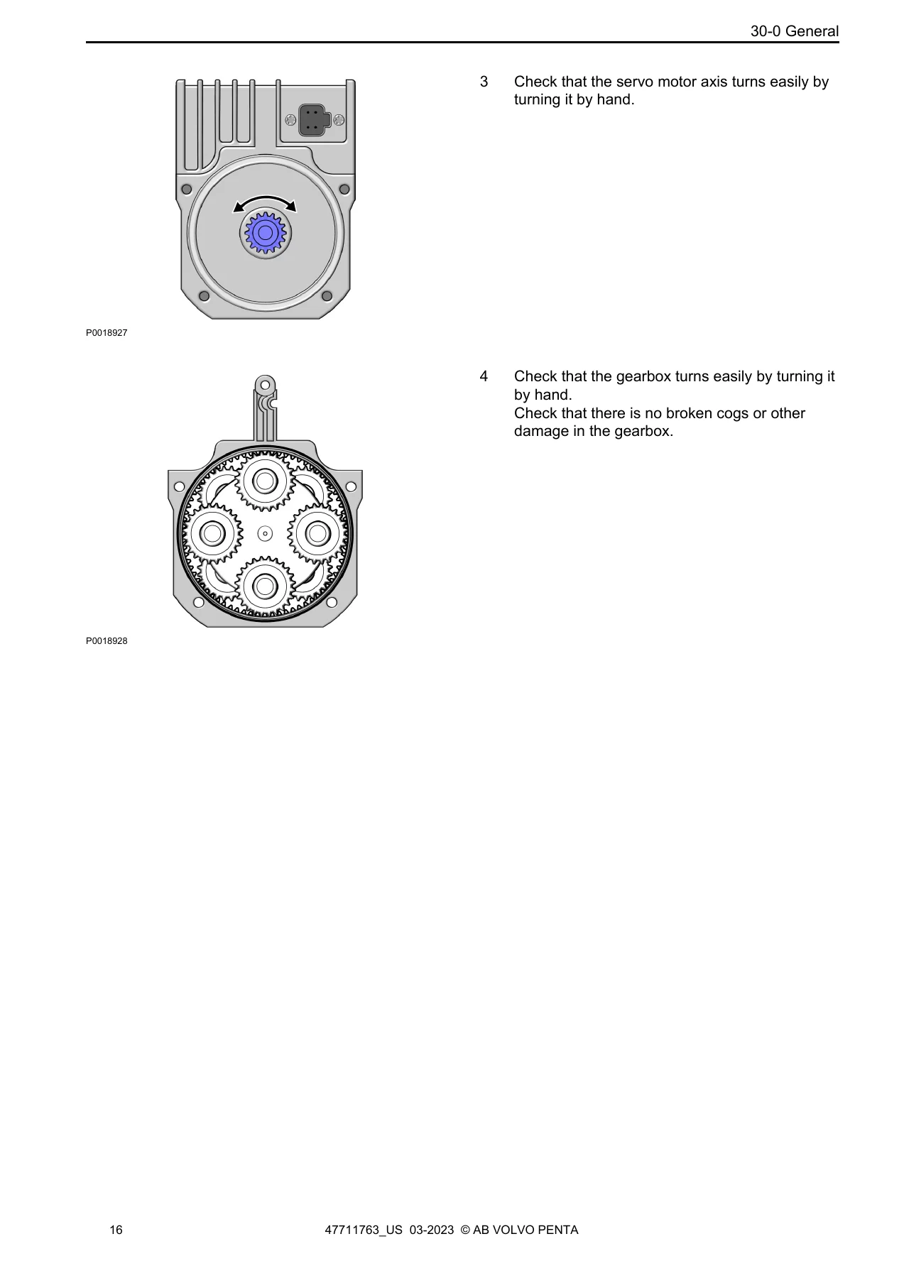
- Servo motor – dismount from interceptor, seal orientation, interceptor shaft torque check, movement range check, servo motor function check, gearbox inspection
- Volvo Penta Glass Cockpit – service and support setup, fault tracing, software version checking, update procedure, power, button, touchscreen, Garmin Marine Network and NMEA 2000 device issues, navigation and mapping
- Faulttrace Procedure – fault tracing flow for the DPI steering function
- Fault code information – BCM (Battery Control Module)
- Fault code information – HCU (Helm station Control Unit)
- Fault code information – ICM (Interceptor Control Module)
- Fault code information – PCU (Powertrain Control Unit)
- Fault code information – SCM (Steering Control Module)
- Fault code information – SUS (Servo Unit Steering)
- Fault code information – VMM (Vessel Main Module)
- Fault code information – SCU (Steering Control Unit)
- Measurements and Fault indication
- CPM / DTC Matrix
- Thruster System DTC matrix
- Wiring diagram reference section
Each fault code entry in the diagnostic chapters follows a consistent structure: failure type, failure event, possible root cause, DTC test conditions, DTC detection time, symptom, corrective action and, where relevant, connector information with specific pin references. That means a technician working through an active fault is not simply told what the code means, but is given the measured threshold that triggers it, how long the condition must persist before the code sets, what the operator will actually notice, and the ordered steps to confirm and correct the problem. Codes span everything from a blown fuse on the BCM supply and a stuck button on a helm panel, through to servo motor over-temperature on an interceptor, low transmission oil pressure on a sterndrive, resolver signal failure on an IPS steering actuator, and CAN bus-off conditions on the EVC, multilink and steering networks.
System Architecture and Node Coverage
The manual opens by explaining that EVC is a distributed system built from smaller electronic units, or nodes, placed at convenient points around the boat. The driveline control system (PCU) sits on the engine, the helm station control unit (HCU) is located close to the helm, the steering servo unit (SUS) lives in the drive leg, and the steering control unit (SCU) is typically found on the inboard side of the transom. A CAN data link ties the nodes together so they can exchange information and use each other’s services, which is what allows the amount of cable installation to be reduced so dramatically compared with conventional wiring.
Because each node is programmed to communicate with a specific engine, and because software can vary with engine type, equipment and parameter settings, the manual stresses the importance of identifying nodes before installation. Identification is done using the ENGINE CHASSIS ID number, checked against labels on the node gables, the engine cover, the engine control unit and the steering unit. The chassis ID on the node labels must match the chassis ID on the engine and SUS/SCU labels, and the same number is used by the Volvo Penta organisation to identify the system in the VODIA diagnostic tool. The chassis ID can also be displayed in the EVC display.
Diagnostic coverage is organised by node, so each control unit has its own block of fault codes with its own connector references. The BCM chapter covers battery banks, battery guards, LIN bus communication with battery sensors, auxiliary network supply and internal module temperature. The HCU chapter covers gear lever units, joystick and steering wheel communication, lanyard safety switches, button panels of every description, key interface faults, autopilot communication, sync bus faults and EVC bus network configuration errors. The ICM chapter deals with the interceptor servo modules one through four. The PCU chapter is the largest, covering transmission speed sensors, shift solenoids, water-in-oil sensing, oil level and oil pressure, oil temperature, trim position controllers and sensors, propeller shaft speed, engine management CAN backbones and the AUX bus nodes. The SCM, SUS and SCU chapters cover steering position sensing, steering servo motors, electromechanical brakes, hydraulic oil temperature and pressure, service and steering solenoids, and drive position sensors. The VMM chapter covers vessel main module communication and auxiliary bus supply.
Measurement Procedures
A substantial section at the back of the manual sets out practical measurement routines for the main buses and sensors. It explains how to check the auxiliary bus, the DPS gateway connection, the EVC bus, the multilink bus at the HCU, the PCU to EECU wiring, the fuel level sensor, the power trim control signal and potentiometer, the propeller shaft speed sensor, the rudder angle sensor, the servo steering motor, the shift solenoids, the steering control bus, the datalink bus terminators and the transmission oil pressure, quality and temperature sensors. Each procedure lists the special tools required, the measurement points with their break-out box pin numbers, and the expected voltage or resistance values, including a resistance table for the transmission oil temperature sensor and a note on verifying the resolver angle parameter through VODIA.
Special Tools Referenced
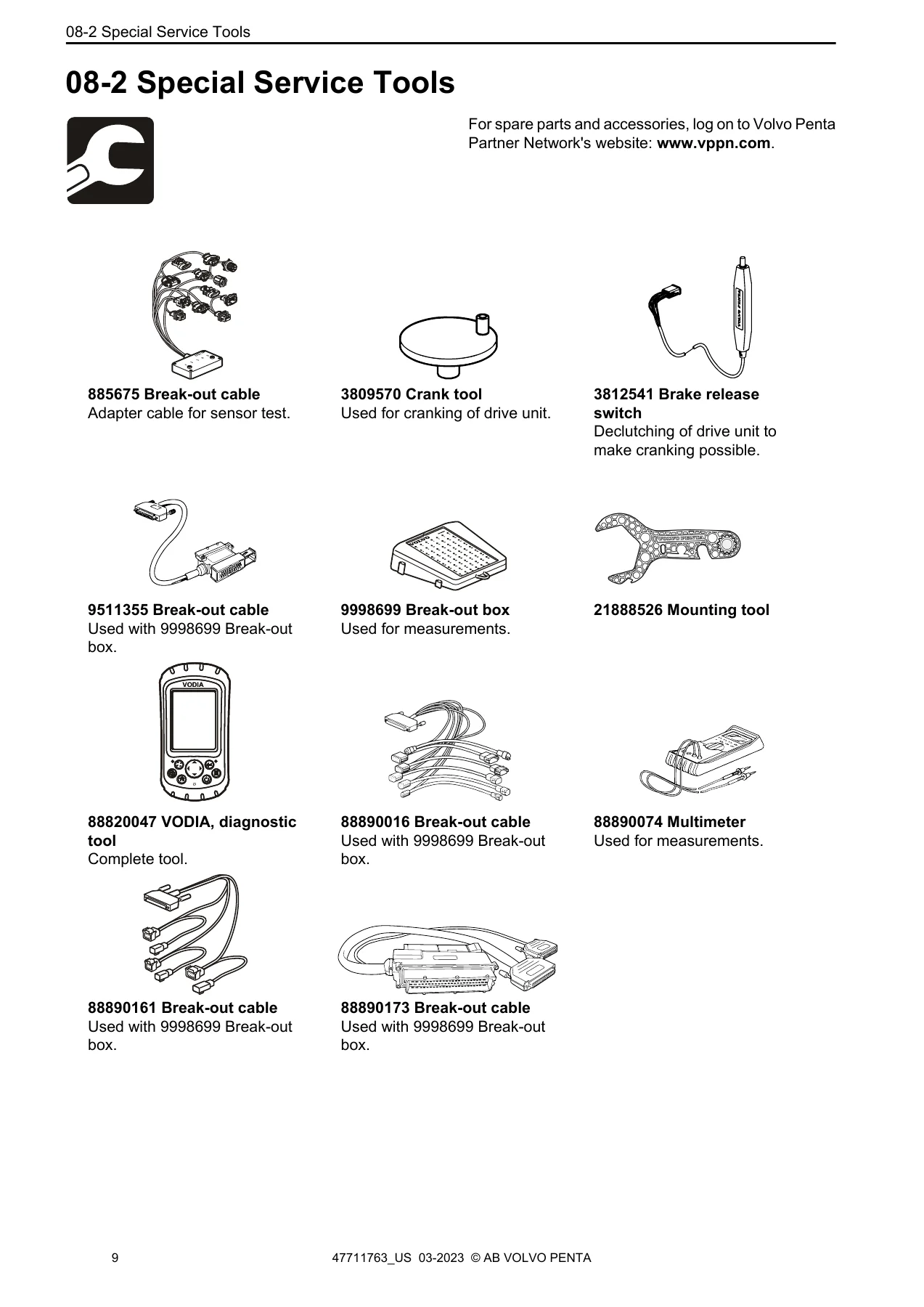
The manual identifies the tooling needed for this work, including break-out cables 885675, 9511355, 88890016, 88890161 and 88890173, break-out box 9998699, multimeter 88890074, the VODIA diagnostic tool 88820047, crank tool 3809570, brake release switch 3812541 and mounting tool 21888526. Safety information is presented up front, with the DANGER, WARNING, CAUTION and NOTICE hierarchy explained, and with specific instructions on immobilising the engine, isolating the main switch, battery handling and the hazards of battery electrolyte.
What This Manual Lets You Do
With this volume on hand you can identify which EVC node is responsible for a reported symptom, pull the correct fault code entry, and follow a defined corrective action path instead of swapping parts on suspicion. You can check bus voltages and terminations at the correct break-out box pins with the expected values in front of you, verify servo motor and gearbox operation on an interceptor before condemning a unit, recalibrate and re-register eKeys after a key is lost, and work through the Glass Cockpit fault tracing tree to decide whether a display problem belongs to the EVC system or to Garmin support. You can confirm chassis ID matching across nodes after a component change, understand when a code points at wiring rather than hardware, and interpret the CPM and thruster DTC matrices to translate J1587 codes into the identifiers used elsewhere.
Electrical faults on a networked boat are rarely solved by guesswork. The difference between a two-hour repair and a two-week parts chase usually comes down to knowing the threshold that set the code, the connector pin that carries the signal, and the order in which the manual expects you to test. That is exactly the information this Group 30 volume is built to supply, and it matters most when a fault is intermittent, when several codes appear at once, or when a previous repair has left the network in a state the system does not recognise.
IMAGES PREVIEW
Delivery is by instant PDF download, with no shipping and nothing to wait for. The file opens on any device you already use in the workshop or on the dock, and you can print the fault code pages or measurement procedures you need for the job in front of you. The Volvo Penta EVC 2 Electrical System Workshop Manual Group 30 is the reference to keep within reach whenever the electrical side of an EVC 2 installation needs attention.
Reviews
There are no reviews yet.