Volvo Penta IPS EVC-C Electrical System Service Manual 77983060
$28.95
Volvo Penta IPS EVC-C Group 30 Electrical System Workshop Manual_77983060 – PDF DOWNLOAD
Description
Volvo Penta IPS EVC-C Group 30 Electrical System Workshop Manual_77983060 – PDF DOWNLOAD
FILE DETAILS:
Volvo Penta IPS EVC-C Group 30 Electrical System Workshop Manual_77983060 – PDF DOWNLOAD
Language : English
Pages : 290
Downloadable : Yes
File Type : PDF
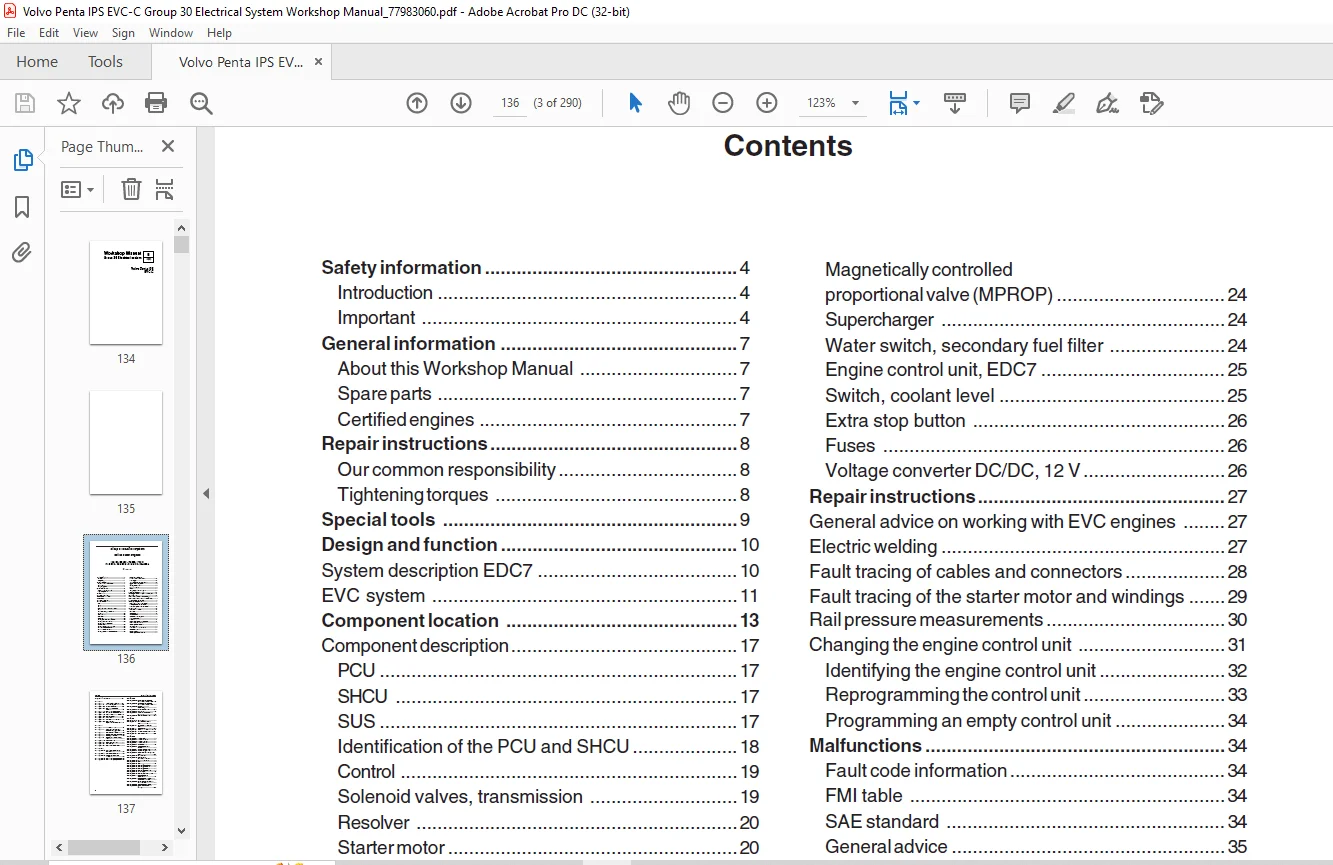
TABLE OF CONTENTS:
Volvo Penta IPS EVC-C Group 30 Electrical System Workshop Manual_77983060 – PDF DOWNLOAD
Safety information 4
Introduction 4
Important 4
General information 7
About this Workshop Manual 7
Spare parts 7
Certified engines 7
Repair instructions 8
Our common responsibility 8
Tightening torques 8
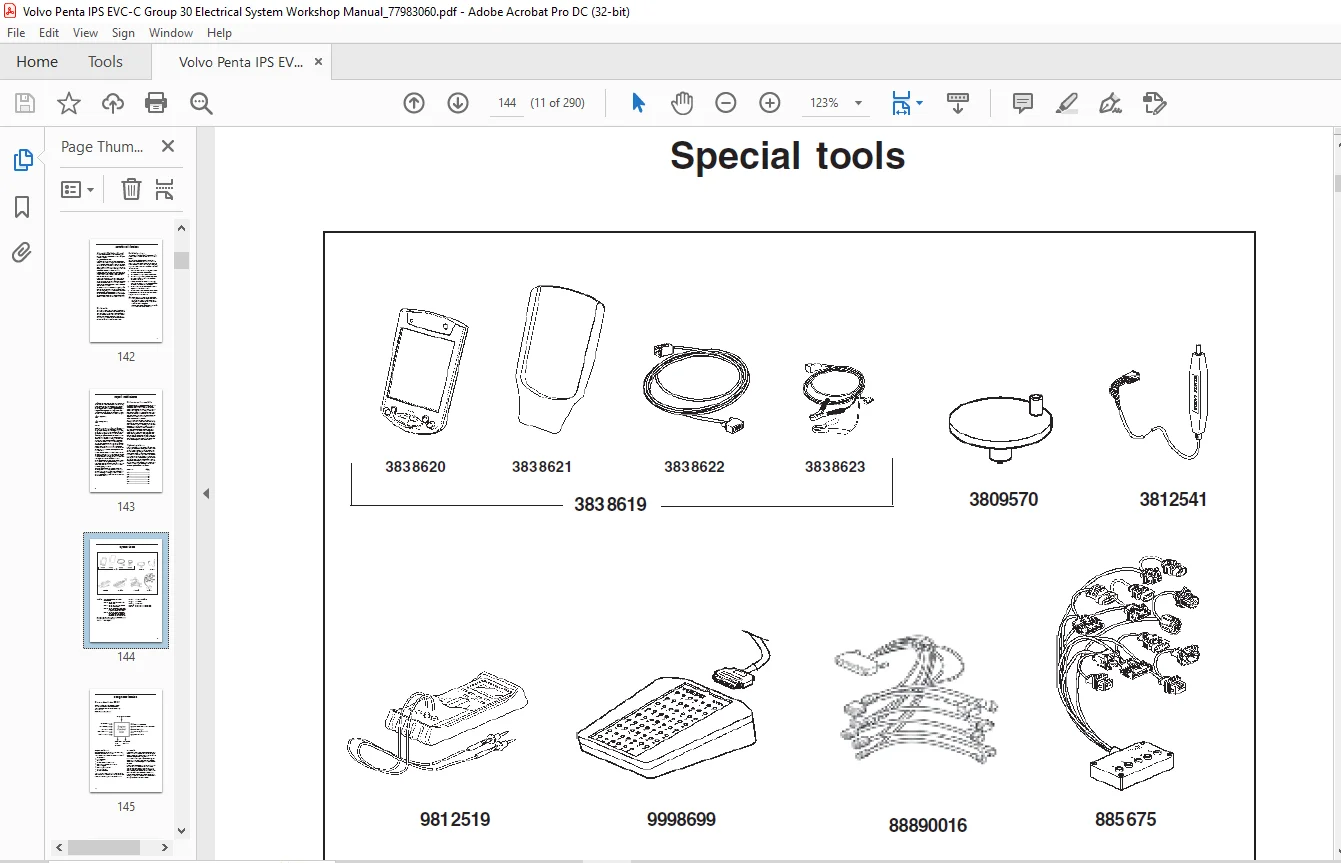
Special tools 9
Design and function 10
System description EDC7 10
EVC system 11
Component location 13
Component description 17
PCU 17
SHCU 17
SUS 17
Identification of the PCU and SHCU 18
Control 19
Solenoid valves, transmission 19
Resolver 20
Starter motor 20
Alternator 20
Injectors 21
Sensor, engine speed (flywheel) 21
Sensor, camshaft position 21
Sensor, boost air pressure/
boost air temperature 22
Sensor, lube oil pressure, engine 22
Coolant temperature sensor 23
Fuel temperature sensor 23
Sensor, common rail pressure (fuel) 23
Contents
Magnetically controlled
proportional valve (MPROP) 24
Supercharger 24
Water switch, secondary fuel filter 24
Engine control unit, EDC7 25
Switch, coolant level 25
Extra stop button 26
Fuses 26
Voltage converter DC/DC, 12 V 26
Repair instructions 27
General advice on working with EVC engines 27
Electric welding 27
Fault tracing of cables and connectors 28
Fault tracing of the starter motor and windings 29
Rail pressure measurements 30
Changing the engine control unit 31
Identifying the engine control unit 32
Reprogramming the control unit 33
Programming an empty control unit 34
Malfunctions 34
Fault code information 34
FMI table 34
SAE standard 34
General advice 35
System introduction, EVC 36
Starting sequence 36
Network 37
Manual fault tracing in bus cables 37
Fault tracing the EVC system 38
Checking the instruments 39
Alarm display 40
Time delay on alarm indication 40
Coolant level monitor 41
Measurements 42
Checking the coolant monitor 43
Contents Group 30: Electrical system
2
Diagnostic Trouble Codes 44
MID 128, PID
MID 128, PID 91 Throttle control position 44
MID 128, PID 97 Water switch, fuel filter 46
MID 128, PID 100 Oil pressure sensor 49
MID 128, PID 105 Boost air temperature
sensor 56
MID 128, PID 106 Boost air pressure sensor 61
MID 128, PID 108 Atmospheric pressure sensor 67
MID 128, PID 110 Coolant temperature sensor 69
MID 128, PID 158 Battery voltage 74
MID 128, PID 164 Fuel pressure 77
MID 128, PID 174 Fuel temperature sensor 83
MID 128, PID 190 Engine speed,
excess speed / calculation 88
MID 128, SID
MID 128, SID 1/2/3/4/5/6 Injectors 1–6 93
MID 128, SID 21 Camshaft position sensor
(speed sensor, camshaft) 96
MID 128, SID 22 Speed sensor (flywheel) 100
MID 128, SID 26 Output, compressor coupling 104
MID 128, SID 40 Output, starter motor 107
MID 128, SID 57 Output, fuel pump (MPROP),
fault 110
MID 128, SID 218 ECM main relay 114
MID 128, SID 231 SAE J1939 Data link 116
MID 128, SID 251 Supply voltage 118
MID 128, SID 254 Engine control unit EDC7 119
MID 128, PSID
MID 128, PSID 50 Fuel pressure, monitoring
(MPROP) 120
MID 128, PSID 51 Redundant Shut-off Path 127
MID 128, PSID 53 Monitoring the pressure
relief valve 128
MID 128, PSID 54 Booster voltage (high bank 1) 130
MID 128, PSID 55 Booster voltage (high bank 2) 132
MID 164, PPID
MID 164, PPID 390 Lever 1 position relative to
potentiometer supply failure 134
MID 164, PPID 391 Lever 2 position relative to
potentiometer supply failure 140
MID 164, PPID 392 Lever potentiometer
supply failure 142
MID 164, PPID 393 Data bus power input 239
MID 164, PPID 394 Key supply 144
MID 164, PPID 397 Main panel communication
failure 147
MID 164, PPID 424 Steering wheel position 245
MID 164, SID
MID 164, PSID139 Auto pilot fault 150
MID 164, SID 226 Neutral switch and lever
position mismatch 152
MID 164, SID 231 Sync bus communication
fault 155
MID 164, SID 240 Program memory fault 210
MID 164, SID 250 SAE J1708 / J1587 data link 157
MID 164, SID 253 Calibration Memory Failure 211
MID 164, SID 254 Internal CPU faults 214
MID 164, PSID
MID 164, PSID 64 Joystick fault 159
MID 164, PSID 65 Joystick on-button 161
MID 164, PSID 66 Joystick hi-button 162
MID 164, PSID 67 Joystick sync fault 163
MID 164, PSID 95 Lever detection 164
MID 164, PSID 96 Calibrated lever travel
too small 166
MID 164, PSID 97 Lever calibration procedure 167
MID 164, PSID 98 Lever(s) not calibrated 168
MID 164, PSID 99 Data bus network configuration
fault 237
MID 164, PSID 103 Neutral button 169
MID 164, PSID 104 Lighting button
(multifunction button) 171
MID 164, PSID 105 Active station button 173
MID 164, PSID 106 Start 175
MID 164, PSID 107 Stop 177
MID 164, PSID 133 Steering wheel data link 179
MID 164, PSID 134 Steering wheel module 181
MID 164, PSID 135 Steering wheel brake 182
MID 164, PSID 136 Steering wheel controller 183
MID 164, PSID 137 Rudder angle 184
MID 164, PSID 138 Steering position divergence 186
MID 164, PSID 140 Incompatible sync
bus version 187
MID 164, PSID 218 Data bus passive / active helm
communication failure 188
MID 164, PSID 226 SHCU communication failure
with other helm 190
MID 164, PSID 231 Incompatible Chassie ID 192
MID 164, PSID 232 Data bus communication
warning 234
Group 30: Electrical system Contents
3
MID 187, PID
MID 187, PID 96 Fuel level 192
MID 187, PID 127 Transmission oil pressure
sensor 196
MID 187, PID 177 Transmission oil temperature
sensor 200
MID 187, PPID
MID 187, PPID 393 Data bus power input 239
MID 187, PPID 400 Transmission sensor supply 203
MID 187, SID
MID 187, SID 231 J1939 Communication
warning / fault 206
MID 187, SID 240 Program memory fault 210
MID 187, SID 253 Calibration Memory Failure 211
MID 187, SID 254 Internal CPU faults 214
MID 187, PSID
MID 187, PSID 10 Incompatible engine type 215
MID 187, PSID 17 Data bus network configuration
fault 237
MID 187, PSID 18 Data bus power output 216
MID 187, PSID 20 Primary solenoid
(high side switch) 219
MID 187, PSID 22 Secondary solenoid
(high side switch) 223
MID 187, PSID 32 Data bus communication with
active helm failure 225
MID 187, PSID 200 No data on engine bus 228
MID 187, PSID 226 SHCU communication failure
with other helm 231
MID 187, PSID 231 Incompatible Chassie ID 192
MID 187, PSID 232 Data bus communication
warning 234
MID 250, PID
MID 250, PID 168 Battery input 242
MID 250, PPID
MID 250, PPID 55 ECU temperature 249
MID 250, PPID 393 Data bus power input 239
MID 250, PPID 424 Steering wheel position 245
MID 250, PPID 426 Rudder angle 247
MID 250, PPID 427 Servo motor temp 250
MID 250, SID
MID 250, SID 240 Program memory fault 210
MID 250, SID 253 Calibration Memory Failure 211
MID 250, SID 254 Internal CPU faults 214
MID 250, PSID
MID 250, PSID 1 Data bus network configuration
fault 237
MID 250, PSID 2 Data bus power output 252
MID 250, PSID 3 Servo motor 254
MID 250, PSID 4 Electro mechanical
rudder brake 259
MID 250, PSID 6 Data bus communication
with active helm failure 262
MID 250, PSID 232 Data bus communication
warning 234
Wiring diagrams 266
Engine D4, D6 266
Controls 268
Pin configuration, PCU 269
Pin configuration, SHCU 270
Calibration before start 271
General 271
Calibration mode 272
Auto configuration 272
Combinations of control levers for EVC
Summary, calibration 274
Lever calibration 276
Idling speed calibration 278
Checking the charging system 279
Technical data 281
References to Service Bulletins 283
Index 284
DESCRIPTION:
Volvo Penta IPS EVC-C Group 30 Electrical System Workshop Manual_77983060 – PDF DOWNLOAD
Safety information:
Introduction:
- This workshop manual contains technical data, de- scriptions and repair instructions for the Volvo
Penta products or product versions noted in the table of con- tents. Check that you have the
correct Workshop Manual for your engine. - Read the available safety information, ”General infor- mation” and ”Repair instructions” in the
workshop manual before you start to do any service work.
General information:
About this Workshop Manual:
- This Workshop Manual contains descriptions and in- structions for the repair of marine diesel
engines D6-310D-B and D6-370D-B. - The engine designation and number are noted on the number plate and engine decal. The engine
designa- tion and number must always be given in all corre- spondence about any product. - The Workshop Manual is produced primarily for the use of Volvo Penta workshops and service techni-
cians. This assumes that people who use the Manual have basic knowledge of marine drive systems and
can do the tasks of a mechanical or electrical nature associated with the trade. - Volvo Penta constantly improves its products, so we reserve the right to make modifications without
prior notification. All information in this manual is based on product data which was available up
to the date on which the manual was printed. Any material changes introduced into the product or
service methods after this date are notified by means of Service Bulletins.
IMAGES PREVIEW OF THE MANUAL:
Contact us: [email protected]
https://vimeo.com/871800088?share=copy
PLEASE NOTE:
- This is the SAME MANUAL used by the dealerships to diagnose your vehicle
- No waiting for couriers / posts as this is a PDF manual and you can download it within 2 minutes time once you make the payment.
- Your payment is all safe and the delivery of the manual is INSTANT – You will be taken to the DOWNLOAD PAGE.
- So have no hesitations whatsoever and write to us about any queries you may have : heydownloadss @gmail.com
S.V