
Volvo VM & EM EU5/EU6 Wiring Diagrams Service Manual – CHID E190426- PDF
Original price was: $52.95.$34.95Current price is: $34.95.
Complete Volvo wiring diagram service information for VM and EM trucks built to EU5/EU6, valid from chassis ID E190426-. Order number 89595948, Release 02, 124 pages of circuit diagrams, connector pinouts, fuse, relay and component lists.
Description
This is the Volvo service information wiring diagram manual covering the VM and EM truck range built to EU5/EU6 emissions standards, valid from chassis ID E190426-. Issued by Volvo Truck Corporation under order number 89595948, Release 02, it is the electrical reference a technician reaches for when a circuit has to be traced, a connector pin identified, or a fuse or relay located without guesswork.
File Details
- Manual type: Wiring diagram / service information
- Brand: Volvo
- Model: VM, EM (EU5/EU6)
- Language: English
- Page count: 124
- File format: PDF
- Order number: 89595948
- Edition / revision: Release 02
- Date: 2023 (designs and methods up to January 2023)
- Chassis ID coverage: E190426-
Chapters Covered
- AA Power supply, starter system
- AG Accessories power supply
- BA Engine interface
- BA1-BA6 MDE8 engine interface variants
- BB1 VECU
- BB2 VECU – ESP switches
- BY_1 TGW III
- CE Position lights and DRL
- CE1 Headlights
- CF Spot lights
- CG Auxiliary fog lights
- CK Brake lights
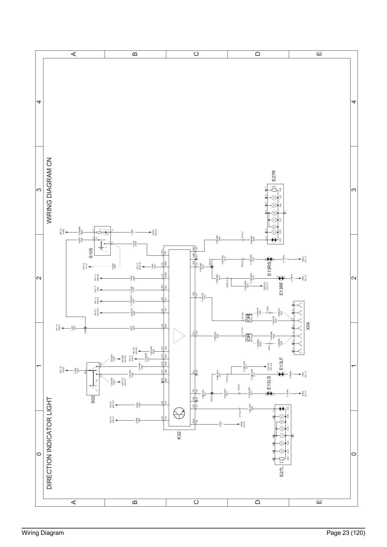
- CN Direction indicator light
- CV1 ACM 2.0
- CV2 EATS – MDE EATS harness
- CV3 ACM 2.0 – EURO5 & EURO6
- CV4 ACM 2.0 – EURO5
- DL Differential lock
- DL_2 Differential lock 6″4
- DP Volvo AMT-G
- DQ Manual (EURO6) gearbox
- EA Reversing light
- EE EBS7
- EF ABS trailer connection
- EG EBS7 – front axle modulator
- EH EBS7 – rear axle modulator
- EI EBS7
- ER Interior light
- EX 12V power supply
- EZ Bodybuilder
- FA Horn
- FW Fifth wheel light
- GA Windscreen wiper and washer
- GF OBD interface
- HA Climate unit air conditioner
- HD Air cooler
- HG Electr. heated/operat. mirror
- HM Fuel filter heater
- IO BBM
- JB Radio base on upper shelf
- KB El. window winders
- KH Central door locking
- LD Power take-off
- MA Bogie lift rear
- MD Front bogie lift / load sensor
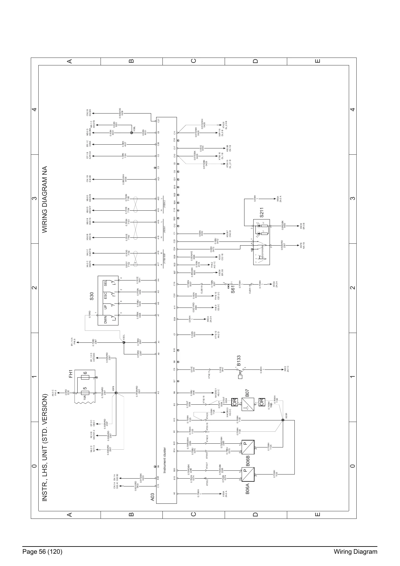
- NA Instr., LHS, unit (std. version)
- NC Tachograph
- XA Bus J1587
- XB CAN J1939
- ZA Ground connection
Power Supply and Starting
The AA section lays out the battery feed, main switch and starter circuit, while AG covers the accessory power supply. Both are drawn with the supply rails +, +30 and +DR clearly marked so you can see exactly which circuits are live with the key in the driving, preheating or starting position.
Engine Interface and Management
BA through BA6 handle the engine interface for the MDE8 engine management platform, including the EURO5 and the cold EGR/ESCR variants. The wiring here is what you need when an engine-side sensor, actuator or ECU pin has to be checked against the harness.
Vehicle Control, Body Builder and Telematics
BB1 and BB2 cover the VECU and its ESP switches, BY_1 documents the TGW III telematics gateway, and EZ gives the body builder the interface information needed to add equipment without disturbing factory circuits.
Lighting
The lighting group runs from position lights and daytime running lamps through headlights, spot lights, auxiliary fog lights, brake lights and the direction indicator circuit. Each diagram shows the control unit, the switch, the lamps and the connectors that join them.
Braking, ABS and EBS
EE, EF, EG, EH and EI cover the EBS7 system across the tractor and trailer, including the front and rear axle modulators and the ABS trailer connection. Wheel-speed sensor routing and modulator wiring are drawn in full.
Transmission, Driveline and PTO
DP documents the Volvo AMT-G transmission, DQ the EURO6 manual gearbox, and EA, DL and DL_2 the reversing light, differential lock and 6″4 differential lock circuits. The AMT-G section is the one to open when a gear-shift fault has to be traced back through the harness.
Climate, Cab Comfort and Accessories
HA, HD, HG, HM, KB, KH and ER together cover the air conditioner, air cooler, heated and operated mirrors, fuel filter heater, electric window winders, central door locking and interior lighting.
Instrumentation, Tachograph and Diagnostics
NA is the instrument cluster wiring for the left-hand-drive standard version, NC covers the tachograph and GF the OBD interface. These pages are where cluster pinouts, sender wiring and diagnostic connector pin assignments are documented.
Communication Buses and Grounding
XA and XB document the J1587 and J1939 CAN buses, and ZA is the ground connection diagram showing the earth points used across the vehicle.
Illustrations, Fuses, Relays, Connectors and Components
Beyond the schematics, the manual carries a full illustrations index with harness and component location drawings, a list of fuses, a list of relays, a list of connectors, a list of components, an abbreviations section and the colour codes used for electrical cables. The cable colour coding follows the standard two-colour notation (for example YE/RD for yellow/red), so a wire read off the page can be matched directly on the truck.
What This Volvo VM/EM Wiring Diagram Manual Lets You Do
With these pages on hand, an electrical fault on a Volvo VM or EM EU5/EU6 stops being a process of elimination. You can follow a circuit from the supply rail through the fuse, the relay, the switch and the connector block to the component, confirm which pin carries which signal, and check the earth return against the ZA ground diagram. That is the difference between replacing parts and repairing the fault.
The fuse list, relay list, connector list and component list turn the diagrams into something workable in the workshop, because every symbol on a schematic can be traced back to a named component and a real connector. The illustrations index adds the physical view: harness routing, connector positions on the cab, chassis, engine and rear lighting, so you can find the plug before you start pulling trim.
IMAGES PREVIEW
Because the manual is delivered as an instant PDF download, there is no shipping and no waiting for a printed binder. Open it on a laptop or tablet in the cab, print the two or three pages for the circuit you are chasing, and keep the rest clean. The Volvo VM and EM EU5/EU6 wiring diagram service information is the electrical backbone reference for these trucks, and having it on hand means the next wiring fault is diagnosed with the correct procedure instead of a guess.
Reviews
There are no reviews yet.