Welch Allyn Propaq CS Vital Signs Patient Monitor Service Manual PDF
Original price was: $85.00.$15.95Current price is: $15.95.
Complete Welch Allyn Propaq CS vital signs monitor service manual with functional verification, calibration procedures, troubleshooting guides, repair procedures, field-replaceable units list, technical diagrams, NIBP/IBP calibration, SpO2 module service, CO2 capnography, and expansion module repair instructions.
Description
Welch Allyn Propaq CS Vital Signs Patient Monitor Service Manual PDF DOWNLOAD
DESCRIPTION:
This comprehensive Welch Allyn Propaq CS service manual (Manual Part Number 810-1101-02 Rev A, April 2006) provides complete factory technical documentation for servicing and repairing the Propaq CS Vital Signs Monitor. Essential for biomedical equipment technicians, hospital clinical engineering departments, and authorized Welch Allyn service professionals.
Monitor Overview:
The Welch Allyn Propaq CS is a portable, battery-powered vital signs monitor designed for patient monitoring in various clinical environments including emergency departments, intensive care units, operating rooms, and patient transport.
Key Monitor Features:
- Vital Signs Parameters:
- ECG (Electrocardiogram) monitoring
- SpO2 (Pulse Oximetry) – Masimo SET® or Nellcor Oximax®
- NIBP (Noninvasive Blood Pressure)
- IBP (Invasive Blood Pressure) – up to 2 channels
- Temperature monitoring
- Respiration rate
- CO2 (Capnography) – Sidestream option
- Display: High-resolution color LCD screen
- Battery Operation: Rechargeable lithium-ion battery pack
- Acuity Communication: FlexNet® wireless or hardwire connectivity
- Expansion Module: Optional module for additional parameters
- Thermal Printer: Optional integrated recorder
- Portability: Lightweight design with carry handle
- ParamSet™ Technology: Automatic parameter configuration
Configurations Available:
- Various SpO2 technology options (Masimo or Nellcor)
- With or without expansion module
- CO2 capnography option
- Acuity communication options
- Printer option
TABLE OF CONTENTS
CHAPTER 1 – SAFETY SUMMARY (Pages 1-4)
- Warnings (Pages 1-2)
- Qualified service personnel requirements
- Federal law restrictions (USA)
- Safe positioning and handling
- MRI and hyperbaric chamber restrictions
- Autoclave warnings
- Power adapter inspection
- Cable and electrode safety
- Acuity connection warnings
- Medical system safety standards (IEC 60601-1-1)
- Patient cabling routing
- Electrosurgery precautions
- Explosion hazard warnings
- Battery safety
- Defibrillator protection
- SpO2 sensor warnings
- High-voltage hazards
- Definitions (Page 3)
- WARNING symbol meaning
- CAUTION symbol meaning
- NOTE symbol meaning
- Symbols (Page 3-4)
- International safety symbols
- Equipment markings
- Regulatory compliance symbols
CHAPTER 2 – OVERVIEW (Pages 5-12)
- Purpose and Scope (Page 5)
- Service manual objectives
- Intended audience
- Document applicability
- Other Applicable Documents (Page 5)
- Operator’s manual reference
- Technical bulletins
- Service updates
- Unpacking Procedure (Page 5-6)
- Initial inspection
- Shipping damage assessment
- Component verification
- Warranty Service (Page 6)
- Warranty coverage details
- Service policies
- Return procedures
- Technical Support Services (Page 6)
- Contact information worldwide
- Support hours
- Service resources
- Recommended Service Intervals (Page 6)
- Preventive maintenance schedule
- Safety inspection intervals
- Calibration frequency
- Identifying Propaq CS Monitor Configurations (Pages 7-9)
- Model number identification
- Serial number location
- Configuration codes
- Optional modules identification
- Identifying the Acuity Communication Options (Page 9)
- FlexNet wireless
- Hardwire connectivity
- Network configuration
- Monitor Controls (Page 9)
- Front panel buttons
- Soft keys
- Navigation controls
- Self Test and Service Menus (Pages 9-11)
- Accessing service mode
- Self-test procedures
- Service menu navigation
- Diagnostic functions
- Service Test Screens (Pages 11-12)
- Test screen descriptions
- Status indicators
- Diagnostic displays
CHAPTER 3 – FUNCTIONAL VERIFICATION (Pages 13-40)
- Introduction (Page 13)
- Functional verification overview
- When to perform tests
- Test equipment requirements
- Safety Tests (Pages 15-17)
- Electrical safety testing:
- Ground continuity test
- AC/DC leakage current measurements
- Patient leakage current test
- Dielectric strength test
- Test procedures and acceptance criteria
- Required test equipment
- Electrical safety testing:
- Functional Verification (Pages 17-40)
- ECG Functional Tests:
- Lead connection verification
- Waveform display verification
- Heart rate accuracy test
- Alarm functionality
- Realtime ECG output test
- SpO2 Functional Tests:
- Sensor recognition
- Pulse rate accuracy
- SpO2 accuracy verification
- Alarm testing
- Pleth waveform verification
- NIBP Functional Tests:
- Pressure accuracy verification
- Pump operation test
- Valve operation test
- Leak test
- Overpressure protection test
- IBP Functional Tests:
- Zero calibration verification
- Pressure accuracy testing
- Waveform display verification
- Dual-channel operation
- Temperature Functional Tests:
- Probe recognition
- Temperature accuracy
- Dual-channel verification
- Respiration Functional Tests:
- Rate accuracy
- Lead-off detection
- Waveform display
- CO2 Functional Tests (if equipped):
- Warm-up verification
- Accuracy testing
- Waveform display
- Sample line verification
- Display and User Interface Tests:
- Screen display verification
- Button functionality
- Alarm indicator testing
- Audio alarm testing
- Battery and Power Tests:
- Battery charge verification
- AC adapter operation
- Battery operation time
- Power-on self-test
- Printer Tests (if equipped):
- Print quality verification
- Paper feed operation
- ECG Functional Tests:
CHAPTER 4 – CALIBRATION (Pages 41-52)
- Introduction (Page 41)
- Calibration overview
- When calibration is required
- Calibration intervals
- Equipment Needed (Page 42)
- Required test equipment list
- Calibration tools
- Simulators and standards
- Setup (Pages 42-44)
- Test bench configuration
- Safety precautions
- Equipment connections
- Recharger Supply Adjustments (Pages 44-46)
- Voltage adjustment procedures
- Current limit settings
- Test point locations
- Measurement procedures
- Main Power Supply Adjustments (Pages 46-48)
- DC voltage calibration
- Regulation verification
- Load testing
- Ripple measurements
- Calibrating Realtime ECG Out (Page 48)
- ECG output amplitude calibration
- Offset adjustment
- Frequency response verification
- Noninvasive Blood Pressure Calibration (Pages 49-51)
- NIBP calibration procedures:
- Pressure transducer calibration
- Zero offset adjustment
- Span adjustment
- Linearity verification
- Multi-point calibration
- Calibration verification tests
- Acceptance criteria
- NIBP calibration procedures:
- Invasive Blood Pressure (Pages 51-52)
- IBP zero calibration
- Gain adjustment
- Multi-point calibration
- Channel calibration procedures
- MSP Board (MCO2) Calibration (Page 52)
- CO2 sensor calibration
- Zero point calibration
- Span calibration
- Barometric pressure compensation
CHAPTER 5 – TROUBLESHOOTING (Pages 53-56)
- Introduction (Page 53)
- Troubleshooting methodology
- Systematic approach
- Safety precautions
- Screen Messages (Pages 53-55)
- Error message reference:
- System error messages
- Parameter-specific errors
- Communication errors
- Hardware fault messages
- Error code descriptions
- Corrective actions
- Message priority levels
- Error message reference:
- Battery Capacity Check (Pages 55-56)
- Battery health testing
- Capacity measurement
- Replacement criteria
- Battery conditioning
CHAPTER 6 – REPAIR PROCEDURES (Pages 57-102)
- Introduction (Page 57)
- Repair procedure overview
- Safety precautions
- ESD protection requirements
- Propaq CS Monitor Software (Pages 57-58)
- Software version identification
- Software update procedures
- PROM replacement
- Required Tools (Page 58)
- Tool list for disassembly
- Special tools
- Measurement equipment
- Propaq CS Monitor Options (Page 59)
- Configuration identification
- Option modules
- Accessories
- Field-Replaceable Units in the Monitor (Pages 60-62)
- FRU list with part numbers
- Assembly-level replacements
- Ordering information
Main Monitor Repair Procedures:
- Replacing the Power Input Fuse (Page 62)
- Fuse location and access
- Fuse specifications
- Installation procedures
- Replacing the Battery Pack (Pages 62-66)
- Battery removal procedure
- Connector disconnection
- Installation steps
- Safety precautions
- Opening the Monitor (Pages 66-70)
- Disassembly sequence
- Screw locations
- Cable routing notes
- Cover removal procedures
- Closing the Monitor (Page 70)
- Reassembly steps
- Torque specifications
- Cable routing verification
- Replacing the Analog Board (Pages 71-73)
- Board removal steps
- Connector identification
- Installation procedures
- Post-installation testing
- Replacing the Digital Board or Display (Pages 73-75)
- Digital board removal
- Display removal procedures
- Cable management
- Connector locations
- Reinstalling the Digital Board or Display (Page 75)
- Installation sequence
- Alignment procedures
- Connector attachment
- Replacing Recharger Board Fuse (F2) (Page 76)
- Fuse location
- Specifications
- Replacement procedure
- Replacing Air Tubing (Page 77)
- NIBP pneumatic tubing
- Routing diagram
- Connection procedures
- Replacing Cables (Page 78)
- Internal cable replacement
- Cable routing diagrams
- Connector types
- Replacing PROMs (Pages 78-81)
- PROM location
- Extraction procedures
- Installation and verification
- Software version confirmation
- Replacing the Recharger Board (Pages 81-83)
- Board removal procedure
- Installation steps
- Calibration requirements
- Replacing the Pump (Page 83)
- NIBP pump removal
- Installation procedures
- Leak testing
- Replacing the Side Panels (Pages 84-88)
- Panel removal
- Installation steps
- Gasket replacement
Expansion Module Repair Procedures:
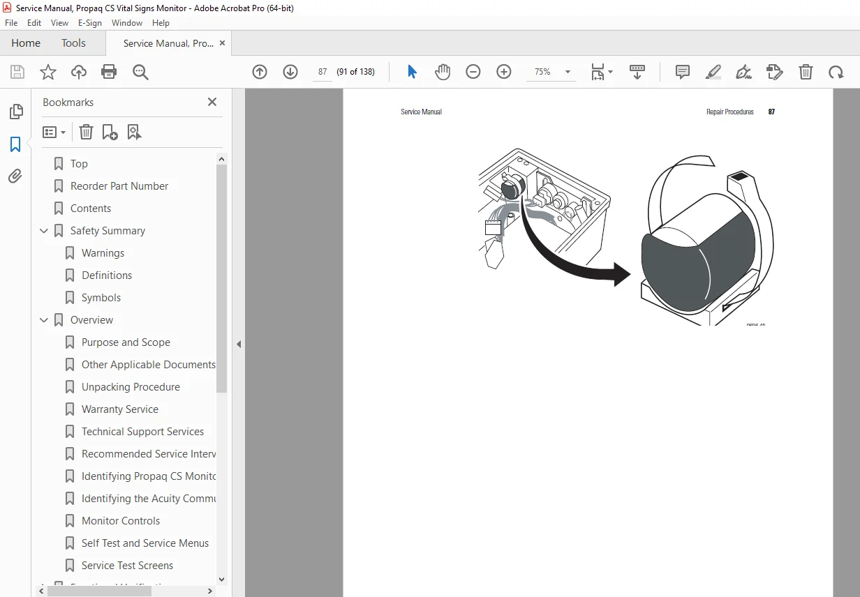
- Expansion Module (Pages 88-91)
- Module overview
- Disassembly procedures
- Component access
- Replacing Expansion Module Front Panel (Page 91)
- Panel removal
- Installation procedures
- Replacing Expansion Module Button Board and Buttons (Page 92)
- Button board removal
- Individual button replacement
- Replacing the Printer (Pages 93-95)
- Printer removal procedure
- Installation steps
- Paper path verification
- Opening the SpO2 Module (Page 95)
- SpO2 module disassembly
- Component access
- Replacing the SpO2 Boards (Pages 96-97)
- Board removal procedures
- Installation steps
- Masimo or Nellcor boards
- Replacing the MSP/SpO2 Boards (Page 97)
- Combined module service
- Board replacement
- Replacing the Sidestream CO2 Assemblies (Pages 98-101)
- CO2 sensor removal
- Pump replacement
- Sample line replacement
- Calibration requirements
- Replacing Expansion Module Side Panels (Page 101)
- Panel removal
- Installation procedures
- Acuity Option Repair Procedures (Pages 101-102)
- FlexNet wireless module
- Hardwire interface board
- Antenna replacement
CHAPTER 7 – TECHNICAL OVERVIEW (Pages 103-124)
- Introduction (Page 103)
- System architecture
- Technical description overview
- System Description (Pages 103-113)
- Block Diagrams:
- Main monitor system block diagram
- Analog board architecture
- Digital board architecture
- Power supply topology
- Functional Description:
- ECG signal processing
- SpO2 signal processing
- NIBP measurement method
- IBP signal conditioning
- Temperature measurement
- Respiration detection
- Power System:
- AC adapter specifications
- Battery charging circuit
- Power distribution
- Voltage regulation
- Digital Processing:
- Microprocessor architecture
- Memory organization
- Software structure
- Communication interfaces
- Block Diagrams:
- NIBP Pneumatics Description (Pages 113-117)
- Pneumatic System:
- Pump operation
- Valve control
- Pressure transducer
- Tubing routing
- Leak detection
- Pneumatic schematic diagram
- Component descriptions
- Pneumatic System:
- Cabling Diagrams (Page 117)
- Internal cable routing
- Connector pinouts
- Signal descriptions
- Expansion Module and Printer Description (Pages 117-119)
- Module architecture
- Printer mechanism
- Interface connections
- Pulse Oximetry Option (SpO2) Description (Pages 119-122)
- SpO2 Technology:
- Masimo SET® technology
- Nellcor Oximax® technology
- Signal processing
- Sensor interface
- Algorithm description
- SpO2 Technology:
- Capnography (CO2) Description (Pages 122-124)
- Sidestream CO2 operation
- Infrared sensor technology
- Sample line system
- Calibration methodology
CHAPTER 8 – FIELD REPLACEABLE UNITS (FRUs) (Pages 125-130)
- Complete FRU Parts List:
- Main monitor assemblies with part numbers
- Expansion module components
- Cables and accessories
- Circuit boards
- Mechanical components
- Consumables
- Ordering information
FRU Categories:
- Analog board assemblies
- Digital board assemblies
- Display assemblies
- Battery packs
- Recharger boards
- Power supplies
- SpO2 modules
- CO2 modules
- Printer assemblies
- Cables and harnesses
- Side panels and covers
- Buttons and switches
- Sensors and transducers
APPENDIX A – MANUFACTURABLE TEST EQUIPMENT (Pages 131-132)
- Custom Test Equipment:
- Test fixture specifications
- Adapter descriptions
- Calibration standards
- Manufacturing tools
APPENDIX B – DYNATECH/NEVADA PATIENT SIMULATOR MODIFICATION (Pages 133-138)
- Simulator Modifications:
- Required modifications for testing
- Circuit modifications
- Setup procedures
- Verification methods
KEY FEATURES OF THIS SERVICE MANUAL:
✓ Official Welch Allyn factory service documentation ✓ Complete functional verification procedures ✓ Comprehensive calibration procedures (NIBP, IBP, ECG, CO2) ✓ Electrical safety testing procedures ✓ Detailed repair procedures with step-by-step photos ✓ Troubleshooting guides with error message reference ✓ Field-replaceable units (FRU) parts list ✓ Technical overview with block diagrams ✓ NIBP pneumatics schematic and description ✓ SpO2 module service procedures (Masimo/Nellcor) ✓ CO2 capnography calibration and repair ✓ Expansion module repair procedures ✓ Cabling diagrams and connector pinouts ✓ Professional biomedical equipment service standards
Applications:
This Welch Allyn Propaq CS service manual is essential for:
- Hospital biomedical engineering departments
- Authorized Welch Allyn service centers
- Independent biomedical equipment repair companies
- Clinical engineering technicians
- Emergency medical services (EMS) equipment technicians
- Medical equipment rental companies
Ideal For:
- Certified biomedical equipment technicians (CBET)
- Clinical engineering professionals
- Hospital technical services staff
- Medical equipment service engineers
- Biomedical technology students
- Healthcare technology management (HTM) professionals
This comprehensive factory service manual provides the complete technical knowledge required to properly diagnose, calibrate, repair, and maintain the Welch Allyn Propaq CS Vital Signs Monitor, ensuring patient safety and optimal equipment performance in critical care environments.
FILE DETAILS:
| Specification | Details |
|---|---|
| Manual Title | Service Manual, Propaq CS Vital Signs Monitor |
| Model Covered | Welch Allyn Propaq CS Vital Signs Monitor |
| Manufacturer | Welch Allyn |
| Manual Part Number | 810-1101-02 Rev A |
| Reorder Part Number | 810-1657-XX (CD), 810-1315-XX (Printed) |
| Publication Date | April 2006 (Rev A) |
| Last Modified | March 23, 2007 |
| Parameters Monitored | ECG, SpO2, NIBP, IBP, Temperature, Respiration, CO2 (optional) |
| SpO2 Technologies | Masimo SET®, Nellcor Oximax® |
| Communication | Acuity FlexNet® wireless, Acuity hardwire |
| Total Pages | 138 pages |
| File Size | 8.6 MB |
| PDF Quality | High-quality factory documentation with photos, diagrams, and schematics |
| Language | English |
| File Format | Searchable PDF (Letter size) |
| Created With | FrameMaker 7.1 / Acrobat Distiller 7.0.5 |