★ TRUSTED BY 321,897+ PROFESSIONALS WORLDWIDE
🏢
Trusted Business
Verified & Licensed
🛡️
Virus Free Files
100% Safe Downloads
🔒
Secure Payment
SSL Protected
Instant Delivery
Available Immediately
Sale!

XCMG XE205D Hydraulic Excavator Workshop Manual PDF – Full Service Repair & Troubleshooting Guide

Original price was: $39.95.Current price is: $24.95.

Complete 498-page XCMG XE205D Hydraulic Excavator Workshop Manual covering engine, hydraulic system, swing and travel motors, electrical control, fault diagnosis, torque values, and step-by-step disassembly and assembly procedures.

Instant PDF Download
Available immediately
💾
Save to Your Device
Download & keep forever
🛡️
Antivirus Scanned
100% virus-free
🌍
Trusted Worldwide
175,000+ customers

Description

XCMG XE205D Hydraulic Excavator Workshop Manual

This XCMG XE205D Hydraulic Excavator Workshop Manual is a comprehensive 498-page technical service and repair guide prepared for experienced technical staff. It delivers the maintenance and repair information needed to keep the XE205D excavator operating safely and efficiently, including technical data, maintenance standards, required tools, step-by-step disassembly and reassembly procedures, and critical safety notices that must be observed during every operation. Whether you are performing routine maintenance, diagnosing a fault code, or overhauling the main hydraulic pump, this XCMG XE205D workshop manual provides the detailed procedures and specifications to complete the job correctly.

File Details

  • Manual Type: Workshop Manual (Service & Repair)
  • Brand: XCMG (Xuzhou XCMG Excavator Machinery Co., Ltd.)
  • Model: XE205D Hydraulic Excavator
  • Overall Machine Part Number: 310606925
  • Language: English
  • Page Count: 498 pages
  • File Format: PDF
  • Version: XE205D Hydraulic Excavator Workshop Manual – 00

Chapters Covered

The XCMG XE205D workshop manual is organized into clearly defined chapters that guide you from general safety and workshop practices through to complete component overhaul. The table of contents includes:

IMAGES PREVIEW

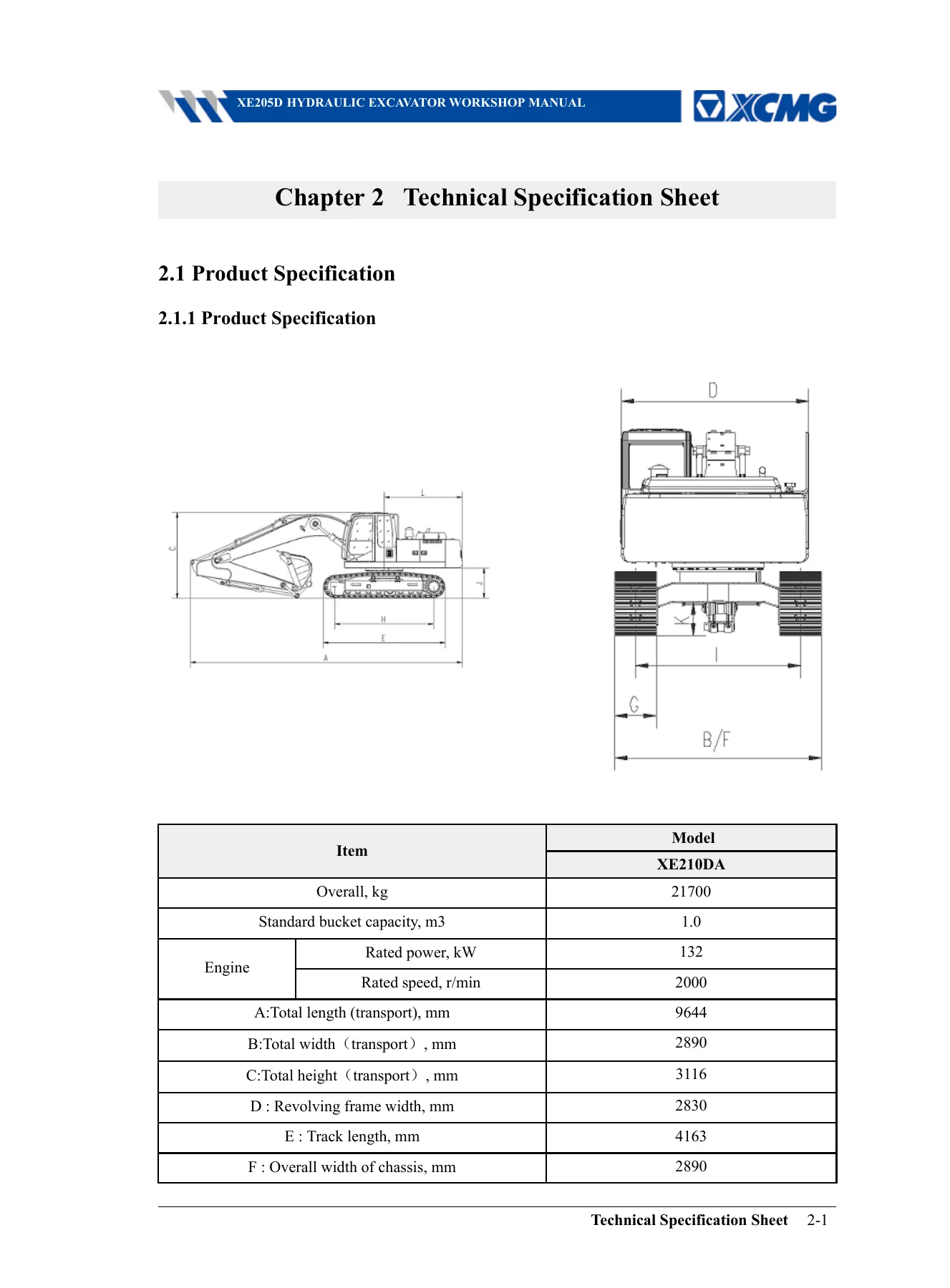
XCMG XE205D Hydraulic Excavator Workshop Manual PDF - Full Service Repair & Troubleshooting Guide — PDF page 35 preview
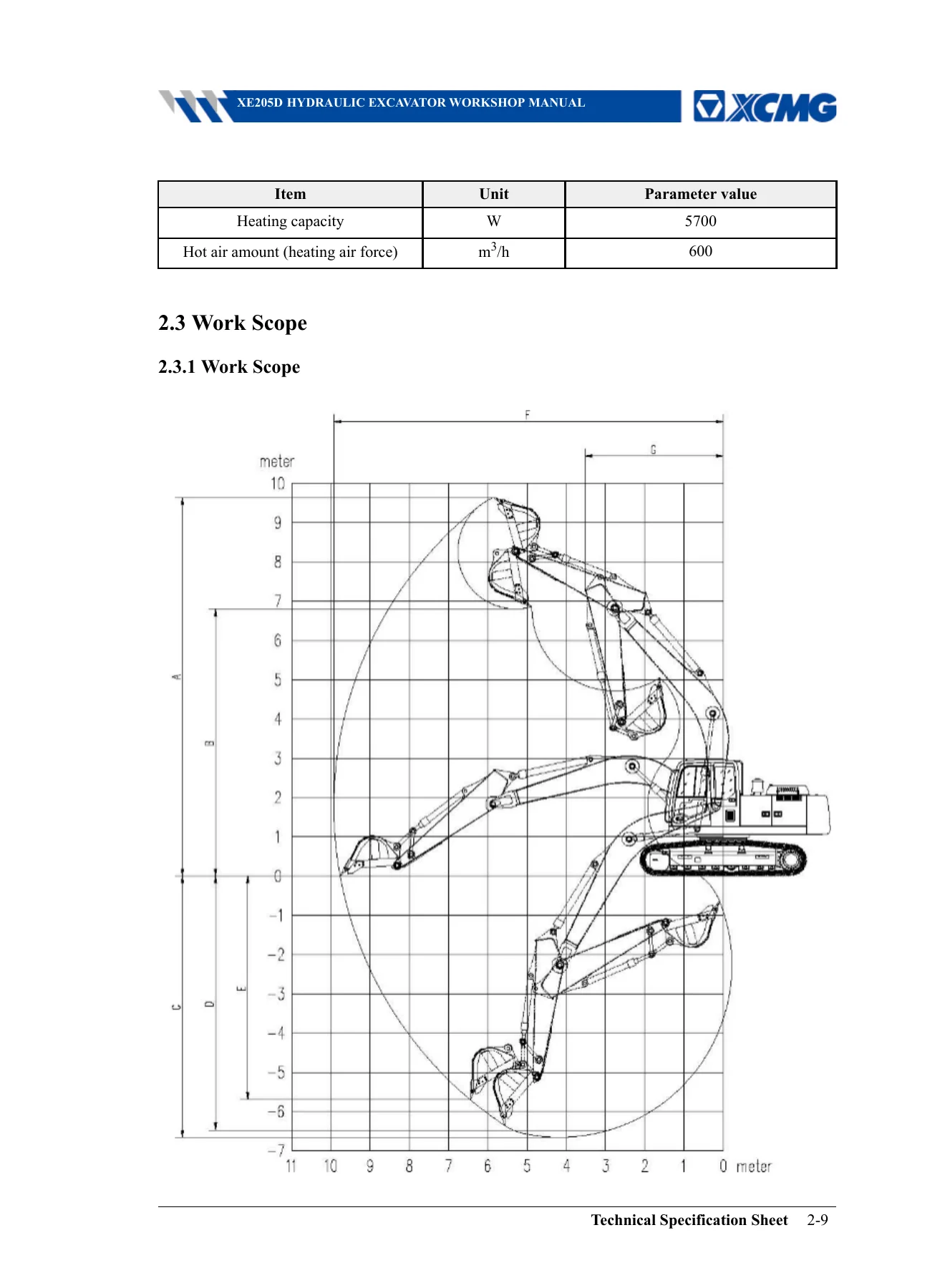
XCMG XE205D Hydraulic Excavator Workshop Manual PDF - Full Service Repair & Troubleshooting Guide — PDF page 43 preview
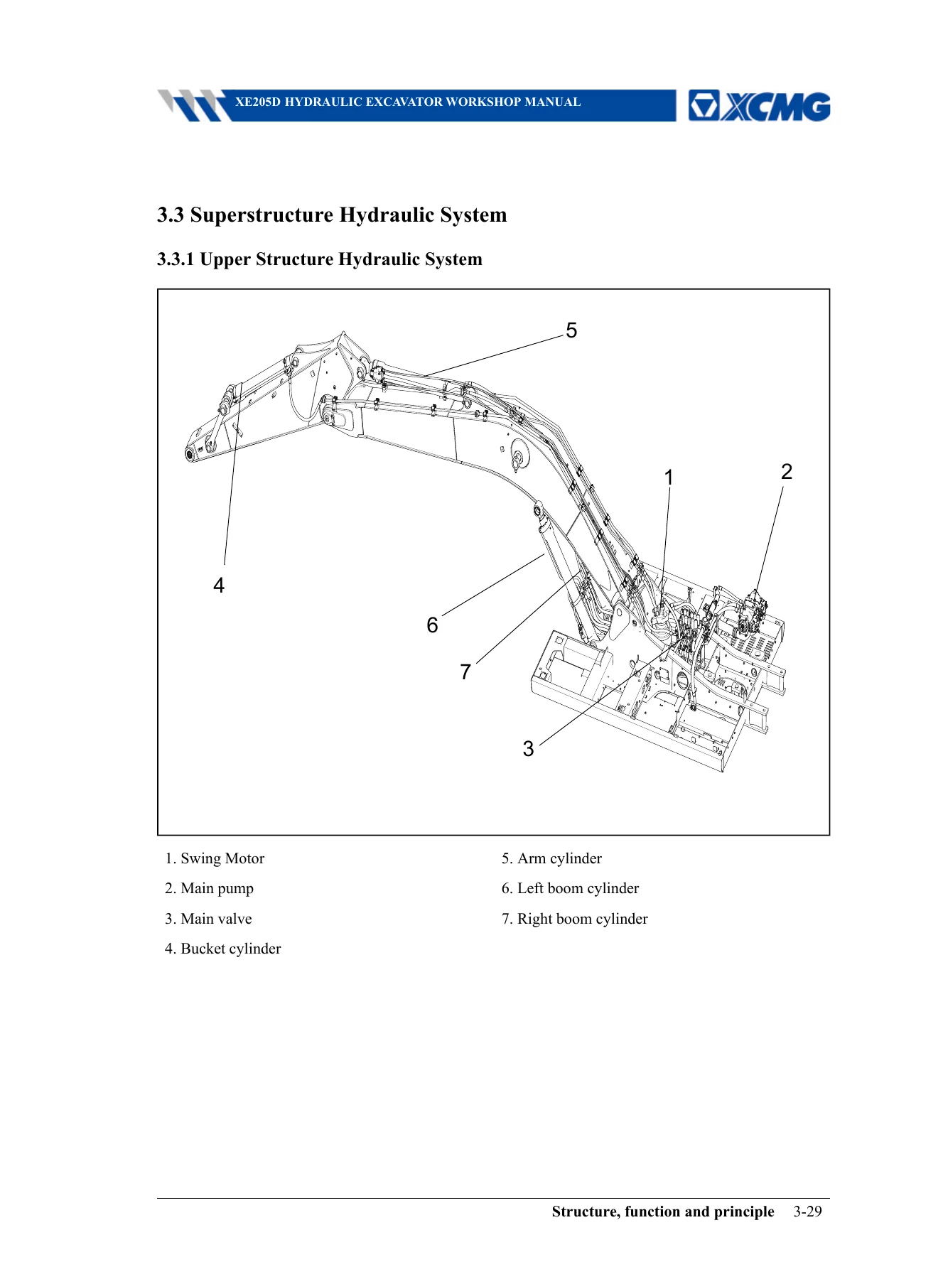
XCMG XE205D Hydraulic Excavator Workshop Manual PDF - Full Service Repair & Troubleshooting Guide — PDF page 73 preview

  • 1. Preface & Safety — Safety warnings, workshop manual reading method, maintenance terms, handling of electrical and hydraulic components, wire code reading.
  • 2. Technical Specification Sheet — Product specification, part specifications for power system, hydraulic system, chassis walking device, electrical system, and air conditioner system; work scope.
  • 3. Structure, Function and Principle — Slewing mechanism (swing mechanism, swivel, swing reducer, swing motor, swing bearing); hydraulic pilot control system (hand pilot valve, traveling pilot valve, pilot valve group); superstructure hydraulic system (hydraulic pump, hydraulic cylinder); hydraulic tank; engine cooling system; chassis walking device (undercarriage assembly, track assembly, tensioner, travel motor); electric control system (pressure switch, pressure sensor, fuel level sensor, hydraulic oil temperature sensor); air conditioner system.
  • 4. Test and Adjust — Measure engine speed and oil consumption ratio; check fuel system leaks; release residual hydraulic pressure; test control oil circuit pilot pressure, main pressure, neutral position unloading pressure; test equipment cylinder, swing, and walking relief pressures; cylinder leakage inspection; exhaust smoke intensity testing; measure equipment oil cylinder settlement; measure single movement speed; measure walking deviation; measure swing bearing clearance; inspect and adjust track tension; test and adjust air conditioner compressor belt.
  • 5. Fault Diagnosis — Troubleshooting overview and precautions; connector pin tables; troubleshooting procedures; fault code tables for machine and engine; diagnostic flow charts for alarms including A101 high hydraulic oil temperature, A104 pilot oil filter blockage, A301 high engine coolant temperature, A302 low fuel level, A305 air filter blockage, E1010/E1020 main pump pressure sensor faults, E1140 hydraulic oil temperature sensor fault, E2010 pump proportional valve fault, and E3030 fuel level sensor fault.
  • 6. Torque and Tool Standard Value Table — Tightening method including thread locker application; general assembly torque table; key position mounting torque table; special material and position mounting torque table.
  • 7. Disassembly and Assembly — Hydraulic pump assembly; control valve assembly; slewing motor assembly and swing reducer; travel motor assembly; hydraulic cylinder assembly (boom, arm, bucket); central rotary joint assembly; work device pilot valve assembly; walking pilot valve assembly; hydraulic tank assembly; crawler track assembly; drive wheel assembly; tensioner assembly; slewing bearing assembly; turntable assembly; cab assembly; air conditioner assembly; counterweight assembly; working device assembly; electronic controller and monitor.

This XCMG XE205D repair manual goes far beyond a simple overview. Each chapter is structured to support real workshop activity: the Structure section explains how components work so you can diagnose faults intelligently, the Test and Adjust chapter supplies the measurement procedures and standard values to verify performance, the Fault Diagnosis chapter maps symptoms to root causes with flow charts and fault code tables, and the Disassembly and Assembly chapter walks you through component overhaul with torque figures, special tool requirements, and safety callouts. The result is a single reference that covers the entire machine — from the engine and hydraulic pump to the swing bearing, travel motor, electrical control system, and air conditioner.

Complete PDF Bookmark Tree

Complete Bookmarks

The complete bookmarks in the “XCMG XE205D Hydraulic Excavator Workshop Manual PDF – Full Service Repair & Troubleshooting Guide” are as follows:

Prefacep. 3
1 Overviewp. 11
1.1 Safety Warningsp. 11
1.2 Workshop manual reading methodp. 16
1.3 Maintenance termsp. 18
1.4 Handling of Electrical and Hydraulic Componentsp. 20
1.5 The way to read the wire codep. 30
2 Technical Specification Sheetp. 35
2.1 Product Specificationp. 35
2.1.1 Product Specificationp. 35
2.2 Part Specificationp. 36
2.2.1 Power systemp. 36
2.2.1.1 Engine Assemblyp. 36
2.2.1.2 Radiator Assemblyp. 37
2.2.2 Hydraulic systemp. 37
2.2.2.1 Hydraulic Pumpp. 37
2.2.2.2 Control Valvep. 37
2.2.2.3 Solenoid Valvep. 37
2.2.2.4 Accumulatorp. 38
2.2.2.5 Swing Motorp. 38
2.2.2.6 Travel Motorp. 38
2.2.2.7 Right Boom Cylinderp. 39
2.2.2.8 Left Boom Cylinderp. 39
2.2.2.9 Arm Cylinderp. 39
2.2.2.10 Bucket Cylinderp. 39
2.2.2.11 Hydraulic Oil Tankp. 40
2.2.3 Chassis walking devicep. 40
2.2.3.1 Tensionerp. 40
2.2.3.2 Track Assemblyp. 40
2.2.3.3 Track Assemblyp. 40
2.2.3.4 Track Assemblyp. 41
2.2.3.5 Swing Bearingp. 41
2.2.4 Electrical systemp. 41
2.2.4.1 Storage Batteryp. 41
2.2.4.2 Storage Batteryp. 41
2.2.4.3 Pressure switchp. 42
2.2.4.4 Pressure sensorp. 42
2.2.4.5 Fuel Level Sensorp. 42
2.2.4.6 Hydraulic Oil Temperature Sensorp. 42
2.2.5 Air Conditioner Systemp. 42
2.2.5.1 Air Conditioner Assemblyp. 42
2.3 Work Scopep. 43
2.3.1 Work Scopep. 43
3 Structure, function and principlep. 45
3.1 Slewing mechanismp. 45
3.1.1 Swing Mechanismp. 45
3.1.2 Swivelp. 46
3.1.3 Swing Reducerp. 48
3.1.4 Swing Motorp. 50
3.1.5 Swing Bearingp. 59
3.2 Hydraulic Pilot Control Systemp. 60
3.2.1 Hydraulic Pilot Control Systemp. 60
3.2.2 Hand Pilot Valvep. 61
3.2.3 Traveling Pilot Valvep. 64
3.2.4 Pilot Valve Groupp. 70
3.3 Superstructure Hydraulic Systemp. 73
3.3.1 Upper Structure Hydraulic Systemp. 73
3.3.2 Hydraulic Pumpp. 74
3.3.3 Hydraulic Cylinderp. 79
3.4 Hydraulic tankp. 83
3.4.1 Hydraulic Oil Tankp. 83
3.5 Engine cooling systemp. 85
3.5.1 Engine Systemp. 85
3.5.2 Radiator Assemblyp. 87
3.6 Chassis walking devicep. 89
3.6.1 Undercarriage assemblyp. 89
3.6.1.1 Chassis Assemblyp. 89
3.6.1.2 Track Assemblyp. 90
3.6.1.3 Tensionerp. 91
3.6.2 Chassis Hydraulic Systemp. 93
3.6.2.1 Lower Structure Hydraulic Systemp. 93
3.6.2.2 Travel Motorp. 94
3.7 Electric Control Systemp. 97
3.7.1 Electric Control Systemp. 97
3.7.2 Pressure Switchp. 99
3.7.3 Pressure Sensorp. 100
3.7.4 Fuel Level Sensorp. 101
3.7.5 Hydraulic oil temperature sensorp. 102
3.8 Air Conditioner Systemp. 104
3.8.1 Air Conditioner Systemp. 104
3.8.2 Air Conditioner Assemblyp. 106
4 Test and Adjustp. 117
4.1 Measure Engine Speedp. 117
4.2 Measure Engine Oil Consumption Ratiop. 117
4.3 Check the Fuel System for Leakp. 118
4.4 Release Residual Pressure from Hydraulic Circuitp. 119
4.5 Test Control Oil Circuit Pilot Pressurep. 121
4.6 Test Main Pressurep. 122
4.7 Test Neutral Position Unloading Pressurep. 123
4.8 Method for Testing Equipment Cylinder Relief Pressurep. 124
4.9 Method of Testing Swing Relief Pressurep. 125
4.10 Test Walking Relief Pressurep. 126
4.11 Equipment Cylinder Leakage Inspection Methodp. 129
4.12 Methods of Checking the Leakage of Swing Motorp. 130
4.13 Methods of Checking the Leakage of Travel Motorp. 131
4.14 Testing Method of Exhaust Smoke Intensityp. 131
4.15 Method of Measuring the Settlement of Equipment Oil Cylinderp. 136
4.16 Measure Single Movement Speed of Equipmentp. 138
4.17 Measure Walking Deviationp. 140
4.18 Measuring Method of Swing Bearing Clearancep. 142
4.19 Inspection and Adjustment of Track Tensionp. 143
4.20 Testing and Adjusting Method of Air Conditioner Compressor Beltp. 149
5 Fault diagnosisp. 153
5.1 Troubleshooting Overview and Precautionsp. 153
5.1.1 Precaution in Fault Diagnosisp. 153
5.1.2 Working Procedure of Fault Diagnosisp. 153
5.1.3 Check before Fault Diagnosisp. 156
5.1.4 Classification and Method of Fault Diagnosisp. 157
5.2 Connector Pin Tablep. 159
5.2.1 Electric Plug Connectorp. 159
5.3 Trouble shootingp. 183
5.3.1 Correct Maintenance and Inspection Procedurep. 183
5.3.2 Trouble Shootingp. 185
5.4 Troubleshooting using fault codesp. 197
5.4.1 Machine Fault Codep. 197
5.4.2 Alarm Informationp. 197
5.4.3 Basic Analytic Table of Fault Code Displayed on the Instrumentp. 199
5.4.4 Basic Analytic Table of Engine Fault Codep. 202
5.5 Troubleshooting Using Trouble Codesp. 216
5.5.1 Fault Diagnosis – A101 Alarm of High Hydraulic Oil Temperaturep. 216
5.5.2 Fault Diagnosis – A104 Pilot Oil Filter Blockage Alarmp. 222
5.5.3 Fault Diagnosis – A301 High Engine Coolant Temperature Alarmp. 226
5.5.4 Fault Diagnosis – A302 Low Fuel Level Alarmp. 229
5.5.5 Fault Diagnosis – A305 Air Filter Blockage Alarmp. 235
5.5.6 Fault Diagnosis – E1010 Main Pump 1 (P1) Pressure Sensor Faultp. 238
5.5.7 Fault Diagnosis – E1020 Main Pump 2 (P2) Pressure Sensor Faultp. 242
5.5.8 Fault Diagnosis – E1140 Hydraulic Oil Temperature Sensor Faultp. 246
5.5.9 Fault Diagnosis – E2010 Pump Proportional Valve Faultp. 250
5.5.10 Fault Diagnosis – E3030 Fuel Level Sensor Faultp. 253
6 Torque and tool standard value tablep. 259
6.1 Tightening Methodp. 259
6.2 General assembly torque tablep. 268
6.3 Key Position Mounting Torque Tablep. 270
6.4 Special Material and Position Mounting Torque Tablep. 272
7 Disassembly and assemblyp. 275
7.1 Disassembly and assembly overview and precautionsp. 275
7.1.1 How to read this chapter (this manual)p. 275
7.1.2 Precautions During Operationp. 276
7.2 Hydraulic pump assemblyp. 277
7.2.1 Disassembly and Re-assembly of Hydraulic Pump Assemblyp. 277
7.2.2 Disassembly and Re-assembly of Main Pumpp. 281
7.3 Control Valve Assemblyp. 291
7.3.1 Disassembly and Re-assembly of Control Valve Assemblyp. 291
7.4 Slewing Motor Assemblyp. 299
7.4.1 Disassembly and Re-assembly of Swing Motor Assemblyp. 299
7.4.2 Disassembly and Re-assembly of Swing Reducerp. 302
7.4.3 Disassembly and Re-assembly of Swing Motorp. 312
7.5 Walking motor assemblyp. 324
7.5.1 Disassembly and Re-assembly of Travel Motor Assemblyp. 324
7.5.2 Disassembly and Re-assembly of Travel Motor Assemblyp. 328
7.6 Hydraulic cylinder assemblyp. 365
7.6.1 Disassembly and Re-assembly of Boom Cylinderp. 365
7.6.2 Disassembly and Re-assembly of Arm Cylinderp. 368
7.6.3 Disassembly and Re-assembly of Bucket Cylinderp. 371
7.7 Central Rotary Joint Assemblyp. 373
7.7.1 Disassembly and Re-assembly of Swivel Assemblyp. 373
7.7.2 Disassembly and Re-Assembly of Swivel Assemblyp. 378
7.8 Work device pilot valve assemblyp. 385
7.8.1 Disassembly and Re-assembly of Pilot Valve Assembly of Equipmentp. 385
7.8.2 Disassembly and Re-assembly of the Pilot Valve Assembly of Equipmentp. 387
7.9 Walking Pilot Valve Assemblyp. 413
7.9.1 Disassembly and Re-assembly of Walking Pilot Valve Assemblyp. 413
7.9.2 Disassembly and Re-assembly of Travel Pilot Valve Assemblyp. 415
7.10 Hydraulic Tank Assemblyp. 442
7.10.1 Disassembly and Re-assembly of Hydraulic Oil Tank Assemblyp. 442
7.11 Crawler with rubber padp. 446
7.11.1 Disassembly and Assembly of Track Assemblyp. 446
7.12 Driving wheel Assemblyp. 451
7.12.1 Disassembly and Re-assembly of Sprocketp. 451
7.13 Tensioner Assemblyp. 452
7.13.1 Disassembly and Re-assembly of Tensioner Assemblyp. 452
7.14 Slewing bearing assembly.p. 454
7.14.1 Disassembly and Re-assembly of Swing Bearing Assemblyp. 454
7.15 Turntable assemblyp. 456
7.15.1 Disassembly and Re-assembly of Revolving Framep. 456
7.16 Cab assemblyp. 459
7.16.1 Disassembly and Re-assembly of Driver’s Cab Assemblyp. 459
7.17 Air Conditioner Assemblyp. 463
7.17.1 Disassembly and Re-assembly of Air Conditioner Assemblyp. 463
7.18 Counterweight assemblyp. 468
7.18.1 Disassembly and Re-assembly of Counterweight Assemblyp. 468
7.19 Working device assemblyp. 470
7.19.1 Disassembly and Re-assembly of Equipment Assemblyp. 470
7.19.2 Disassembly and Re-assembly of Bucket Assemblyp. 474
7.19.3 Disassembly and Re-assembly of Arm Assemblyp. 476
7.19.4 Disassembly and Re-assembly of Boom Assemblyp. 479
7.19.5 Disassembly and Reassembly of Hydraulic Oil Cylinder Assemblyp. 481
7.20 Electronic controllerp. 494
7.20.1 Disassembly and Re-assembly of Electronic Monitorp. 494
7.21 Controller assemblyp. 495
7.21.1 Disassembly and Re-assembly of Controller Assemblyp. 495

What This Workshop Manual Enables You to Do

With the XCMG XE205D Hydraulic Excavator Workshop Manual PDF, you can perform the full range of maintenance, repair, and diagnostic tasks on the XE205D excavator. The manual provides the procedures to:

  • Test and adjust engine speed, main hydraulic pressure, pilot pressure, relief pressures, and neutral unloading pressure.
  • Diagnose faults using machine fault codes and engine fault codes, with detailed diagnostic flow charts for hydraulic oil temperature alarms, pilot oil filter blockage, engine coolant temperature alarms, fuel level alarms, air filter blockage, pressure sensor faults, pump proportional valve faults, and more.
  • Disassemble and reassemble the hydraulic pump, control valve, swing motor, swing reducer, travel motor, hydraulic cylinders, central rotary joint, pilot valves, hydraulic tank, track assembly, sprocket, tensioner, swing bearing, turntable, cab, air conditioner, counterweight, and working device.
  • Check cylinder leakage, swing motor leakage, and travel motor leakage.
  • Measure walking deviation, swing bearing clearance, and equipment cylinder settlement.
  • Inspect and adjust track tension, and test and adjust the air conditioner compressor belt.
  • Apply correct torque values for standard bolts, hose joints, flange connections, and key mounting positions including engine mounts, main pump, swing motor, travel motor, swing bearing, and counterweight.

Having the correct procedures and specifications matters. Hydraulic systems operate at pressures up to 34.3 MPa (normal) and 37.8 MPa (boost), and incorrect assembly or torque can lead to leaks, component damage, or dangerous failures. The XCMG XE205D workshop manual gives you the manufacturer’s specified tolerances, torque values, and step-by-step sequences so you can complete repairs correctly the first time.

Instant PDF Delivery

The XCMG XE205D Hydraulic Excavator Workshop Manual is delivered as an instant PDF download. No shipping, no waiting — you get immediate access to the complete 498-page document. The PDF can be viewed on any device, including laptops, tablets, and smartphones, and can be printed for use in the workshop. Whether you need to look up a torque value at the bench or follow a disassembly sequence step by step, this XCMG XE205D service repair manual is ready when you are.
Reviews

There are no reviews yet.

Be the first to review “XCMG XE205D Hydraulic Excavator Workshop Manual PDF – Full Service Repair & Troubleshooting Guide”

What Our Customers Say

★★★★★ Live reviews from customers
Loading customer reviews...
0
    0
    Your Cart
    Your cart is emptyReturn to Shop
    🛒
    Recently Purchased
    🕒 verified order