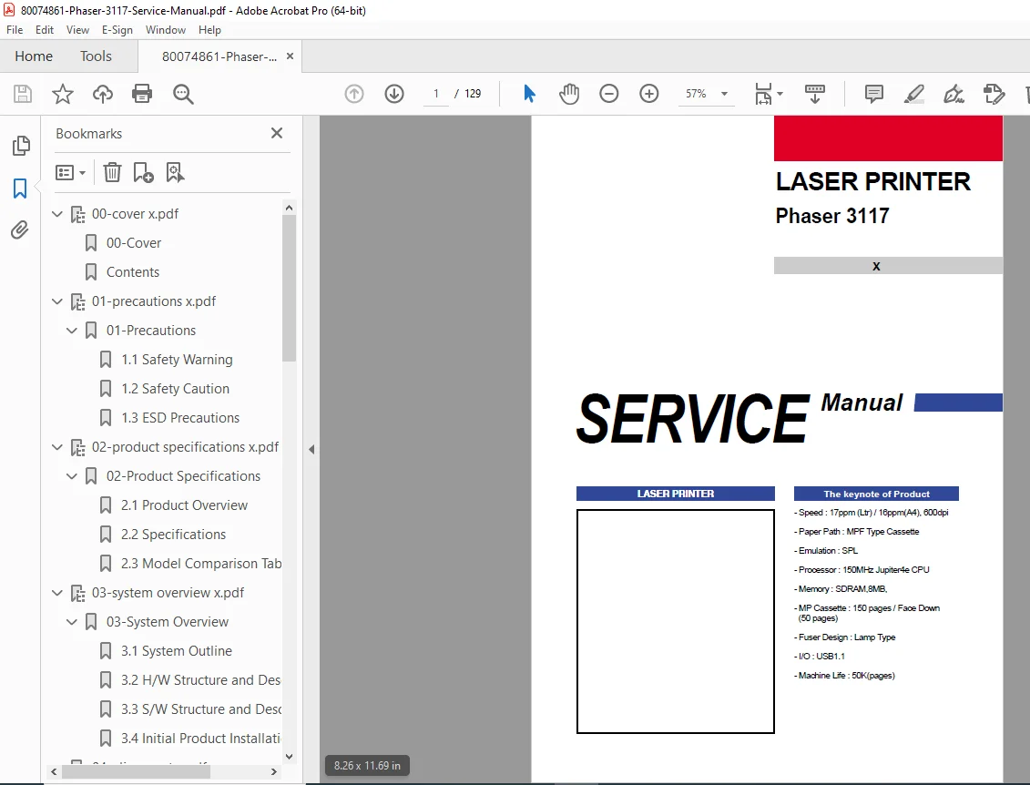
Xerox Phaser 3117 Laser Printer Service Manual PDF Download
Original price was: $85.00.$15.95Current price is: $15.95.
Complete Xerox Phaser 3117 monochrome laser printer service manual with troubleshooting procedures, disassembly/reassembly instructions, LED error messages, parts list with exploded views, schematic diagrams, block diagrams, paper path adjustments, and technical specifications for 17ppm laser printer repair.
Description
Xerox Phaser 3117 Laser Printer Service Manual PDF Download
DESCRIPTION:
This comprehensive Xerox Phaser 3117 service manual (February 2007) provides complete factory technical documentation for servicing and repairing the Xerox Phaser 3117 monochrome laser printer. Essential for authorized Xerox service technicians, independent printer repair specialists, and IT support professionals.
Printer Overview:
The Xerox Phaser 3117 is a compact monochrome laser printer designed for small office and workgroup environments, featuring reliable performance and quality output.
Key Product Features:
- Print Speed: 17 ppm (Letter) / 16 ppm (A4)
- Resolution: 600 dpi
- Paper Path: MPF Type Cassette
- Emulation: SPL (Samsung Printer Language)
- Processor: 150MHz Jupiter4e CPU
- Memory: 8MB SDRAM
- Paper Capacity:
- MP Cassette: 150 pages
- Manual Feed: 50 pages (Face Down)
- Fuser Design: Lamp Type (thermal fuser)
- I/O Interface: USB 1.1
- Machine Life: 50,000 pages
- Compact Design for small office environments
TABLE OF CONTENTS
CHAPTER 1 – PRECAUTIONS (Pages 1-1 to 1-4)
- 1.1 Safety Warning (Pages 1-1 to 1-2)
- Qualified service person requirements
- Do not rebuild warning
- Unauthorized modifications prohibited
- Electric shock prevention
- Fire hazard prevention
- High-voltage component warnings
- Fuser safety precautions (high temperature)
- Laser beam safety
- Power disconnect procedures
- 1.2 Safety Caution (Pages 1-2 to 1-3)
- Equipment damage prevention
- Component handling procedures
- Environmental considerations
- Proper grounding requirements
- Ventilation requirements
- 1.3 ESD Precautions (Page 1-4)
- Electrostatic Discharge protection procedures
- Wrist strap usage
- Anti-static work surface requirements
- IC and circuit board handling
- Grounding techniques
- Component storage procedures
CHAPTER 2 – PRODUCT SPECIFICATION (Pages 2-1 to 2-5)
- 2.1 Product Overview (Page 2-1)
- Printer architecture
- System components
- Design philosophy
- Target market applications
- 2.2 Specifications (Pages 2-1 to 2-4)
- Print Specifications:
- Print speed: 17 ppm (Letter) / 16 ppm (A4)
- Resolution: 600 x 600 dpi
- First page out time
- Warm-up time
- Engine Specifications:
- Processor: 150MHz Jupiter4e CPU
- Memory: 8MB SDRAM
- Print languages: SPL emulation
- Paper Handling:
- Input tray capacity: 150 sheets
- Manual feed: 50 sheets
- Output tray: Face down
- Paper sizes supported
- Paper weight range
- Electrical Specifications:
- Voltage requirements
- Power consumption
- Current ratings
- Fuser power specifications
- Environmental Specifications:
- Operating temperature range
- Storage temperature
- Humidity specifications
- Physical Specifications:
- Dimensions (W x D x H)
- Weight
- Interface Specifications:
- USB 1.1 connectivity
- Cable requirements
- Machine Life: 50,000 pages duty cycle
- Print Specifications:
- 2.3 Model Comparison Table (Page 2-5)
- Feature comparison matrix
- Configuration differences
- Regional variants
CHAPTER 3 – SYSTEM OVERVIEW (Pages 3-1 to 3-24)
- 3.1 System Outline (Pages 3-1 to 3-6)
- Overall system architecture
- Major assembly overview
- Component interaction
- Functional block overview
- 3.2 H/W Structure and Descriptions (Pages 3-7 to 3-18)
- Hardware Architecture:
- Main board components
- LSU (Laser Scanning Unit)
- OPC drum assembly
- Developer unit
- Transfer roller
- Fuser assembly (lamp type)
- Paper feed mechanism
- Power supply (SMPS)
- High-voltage power supply (HVPS)
- Mechanical Components:
- Drive motors
- Clutches and solenoids
- Gears and pulleys
- Sensors and switches
- Paper Path Description:
- Paper pickup mechanism
- Registration assembly
- Transfer process
- Fuser operation
- Exit path
- Hardware Architecture:
- 3.3 S/W Structure and Descriptions (Pages 3-19 to 3-23)
- Software architecture
- Firmware structure
- Control algorithms
- Communication protocols
- Command processing
- 3.4 Initial Product Installation (Page 3-24)
- Unpacking procedures
- Initial setup steps
- Driver installation
- Test print procedures
CHAPTER 4 – ALIGNMENT AND ADJUSTMENTS (Pages 4-1 to 4-11)
- 4.1 Sample Pattern (Page 4-1)
- Test pattern printing
- Quality assessment patterns
- 4.2 Control Panel (Page 4-2 to 4-3)
- Front panel description
- LED indicators
- Button functions
- Status display interpretation
- 4.3 Consumables and Replacement Parts (Page 4-4)
- Toner cartridge specifications
- OPC drum life
- Developer unit replacement
- Fuser lamp replacement intervals
- 4.4 LED Status Error Messages (Page 4-4)
- LED blink patterns
- Error code interpretation
- Fault indication system
- 4.5 Periodic Defective Image (Page 4-5)
- Repetitive defect diagnosis
- Measurement techniques
- Component identification chart
- 4.6 How to use DCU (Pages 4-6 to 4-10)
- Diagnostic Control Utility (DCU) operation
- Service mode access procedures
- Configuration parameters
- Adjustment procedures
- Counter reset functions
- Calibration routines
- 4.7 Paper Path (Page 4-11)
- Paper path adjustment procedures
- Registration timing
- Feed roller adjustment
- Exit sensor calibration
CHAPTER 5 – DISASSEMBLY AND REASSEMBLY (Pages 5-1 to 5-30)
- 5.1 General Precautions on Disassembly (Page 5-1)
- Safety precautions before disassembly
- Tool requirements
- Component handling guidelines
- Screw organization tips
- Cable routing notes
- 5.2 Disassembly and Reassembly (Pages 5-2 to 5-30)
Complete step-by-step procedures with photos:
External Components:
- Top cover removal
- Front cover removal
- Side panels removal
- Rear cover removal
- Paper tray removal
Internal Components:
- Main board removal and installation
- Power supply (SMPS) removal
- High-voltage power supply (HVPS) removal
- LSU (Laser Scanning Unit) removal
- OPC drum cartridge removal
- Developer unit removal
- Transfer roller removal
- Fuser assembly removal and installation
- Fuser lamp replacement
Paper Path Components:
- Paper feed assembly removal
- Pickup roller replacement
- Separation pad replacement
- Registration assembly removal
- Exit assembly removal
Drive System:
- Main motor removal
- Drive gears removal
- Clutch replacement
- Belt replacement
Sensors and Switches:
- Sensor replacement procedures
- Switch removal
- Cable routing diagrams
CHAPTER 6 – TROUBLESHOOTING (Pages 6-1 to 6-30)
- 6.1 Checking Symptoms (Pages 6-1 to 6-3)
- Systematic diagnostic approach
- Symptom identification
- Problem isolation techniques
- 6.2 Bad Discharge (Pages 6-4 to 6-7)
- No power symptoms
- Power supply failure diagnosis
- Voltage testing procedures
- Fuse location and replacement
- Circuit board testing
- 6.3 Malfunction (Pages 6-8 to 6-12)
- Printer does not respond
- Communication errors
- USB connection problems
- Driver issues
- Print job not processing
- Paper feed malfunctions
- Paper jam diagnosis and clearing
- 6.4 Bad Software Environment (Pages 6-13 to 6-16)
- Driver installation problems
- Operating system compatibility
- Firmware update procedures
- Configuration issues
- Communication protocol problems
- 6.5 Bad Image (Pages 6-17 to 6-30)
- Print Quality Problems:
- Blank pages
- Light or faded prints
- Dark or overexposed prints
- Vertical lines or streaks
- Horizontal banding
- Toner smearing
- Background shading
- Spotting or speckling
- Ghosting images
- Uneven density
- Text quality issues
- Image Defect Diagnosis:
- OPC drum problems
- Developer unit issues
- Transfer roller defects
- Fuser problems
- Toner cartridge issues
- LSU alignment problems
- Resolution Procedures for each defect type
- Print Quality Problems:
CHAPTER 7 – EXPLODED VIEWS & PARTS LIST (Pages 7-1 to 7-40)
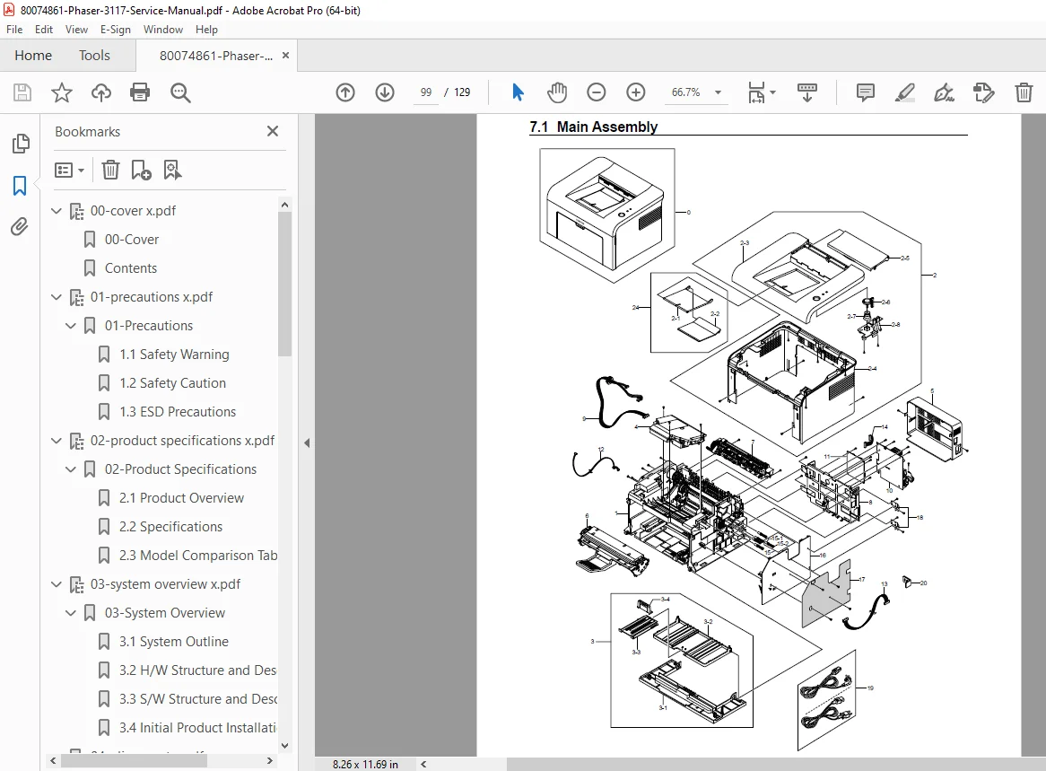
- 7.1 Exploded Views and Parts List (Pages 7-1 to 7-40)
Complete parts catalog with exploded diagrams:
Major Assemblies:
- Overall unit exploded view
- Frame and cover assembly
- Paper feed assembly
- LSU assembly exploded view
- Fuser assembly exploded view
- Main board assembly
- Power supply assembly
Parts List with Part Numbers:
- Mechanical parts
- Electrical components
- Circuit boards
- Motors and sensors
- Rollers and belts
- Covers and panels
- Cables and harnesses
- Screws and fasteners
Part Number Reference:
- Ordering information
- Compatible parts
- Service kit contents
CHAPTER 8 – BLOCK DIAGRAM (Pages 8-1 to 8-2)
- 8.1 System Block Diagram (Page 8-1)
- Overall system architecture
- Component interconnections
- Signal flow diagram
- Power distribution
- 8.2 System Timing Chart (Page 8-2)
- Print sequence timing
- Motor control timing
- Sensor timing relationships
- Paper path timing diagram
CHAPTER 9 – CONNECTION DIAGRAM (Pages 9-1 to 9-5)
- 9.1 Connection Diagram (Pages 9-1 to 9-5)
- Main board connector locations
- Cable routing diagrams
- Harness interconnections
- Connector pinout diagrams
- Signal descriptions
- Ground connections
CHAPTER 10 – SCHEMATIC DIAGRAM (Pages 10-1 to 10-7)
- 10.1 Main Board (Pages 10-1 to 10-4)
- Complete main board schematic
- CPU and memory circuits
- Interface circuits
- Control circuits
- Signal processing
- 10.2 Connector Circuit Diagram (Page 10-5)
- Connector pinout schematics
- Signal routing
- Pin assignments
- 10.3 SMPS Circuit Diagram (Page 10-6)
- Switching Mode Power Supply schematic
- Voltage regulation circuits
- Protection circuits
- Output voltages
- 10.4 HVPS Circuit Diagram (Page 10-7)
- High-Voltage Power Supply schematic
- Charging voltage circuits
- Transfer voltage circuits
- Developer bias voltage
CHAPTER 11 – REFERENCE INFORMATION (Pages 11-1 to 11-5)
- 11.1 Troubleshooting Tools (Page 11-1)
- Required tools list
- Test equipment specifications
- Diagnostic utilities
- 11.2 Acronyms and Abbreviations (Pages 11-2 to 11-3)
- Technical terms glossary
- Abbreviation definitions
- 11.3 Selecting Printer Locations (Page 11-4)
- Environmental requirements
- Ventilation needs
- Space requirements
- Power outlet specifications
- 11.4 Sample Test Patterns (Page 11-5)
- Diagnostic test prints
- Quality assessment patterns
- Alignment patterns
CHAPTER 12 – CIRCUIT DESCRIPTION (Pages 12-1 to 12-10)
- 12.1 Engine Controller (Pages 12-1 to 12-10)
- Circuit Theory of Operation:
- Main controller operation
- CPU architecture
- Memory management
- I/O control
- USB interface circuit
- Motor control circuits
- Sensor input circuits
- Laser control circuit
- Fuser control circuit
- High-voltage control
- Safety interlock circuits
- Circuit Theory of Operation:
KEY FEATURES OF THIS SERVICE MANUAL:
✓ Official Xerox factory service documentation ✓ Complete troubleshooting procedures with symptom diagnosis ✓ Step-by-step disassembly/reassembly instructions with photos ✓ LED error message interpretation guide ✓ DCU (Diagnostic Control Utility) operation procedures ✓ Complete parts list with exploded views and part numbers ✓ Circuit schematics for main board, SMPS, and HVPS ✓ Block diagrams and timing charts ✓ Print quality troubleshooting guide ✓ Paper path adjustment procedures ✓ Connection diagrams with pinouts ✓ ESD precautions and safety procedures ✓ Professional Xerox service standards
Applications:
This Xerox Phaser 3117 service manual is essential for:
- Authorized Xerox service centers
- Independent printer repair shops
- IT support departments
- Small office technical support
- Computer repair businesses
- Technical training programs
Ideal For:
- Professional printer repair technicians
- Xerox certified service engineers
- IT support specialists
- Office equipment technicians
- Technical students and apprentices
- Small business IT personnel
- Mobile printer repair services
This comprehensive factory service manual provides the complete technical knowledge required to properly diagnose, repair, and maintain the Xerox Phaser 3117 laser printer, ensuring optimal performance and print quality.
FILE DETAILS:
| Specification | Details |
|---|---|
| Manual Title | Phaser 3117 Laser Printer Service Manual |
| Model Covered | Xerox Phaser 3117 Monochrome Laser Printer |
| Manufacturer | Xerox Corporation |
| Publication Date | February 2007 |
| Print Speed | 17 ppm (Letter) / 16 ppm (A4) |
| Resolution | 600 x 600 dpi |
| Processor | 150MHz Jupiter4e CPU |
| Memory | 8MB SDRAM |
| Interface | USB 1.1 |
| Machine Life | 50,000 pages |
| Total Pages | 129 pages |
| File Size | 7.9 MB |
| PDF Quality | High-quality factory documentation with photos, diagrams, and schematics |
| Language | English |
| File Format | Searchable PDF (A4 size, optimized) |