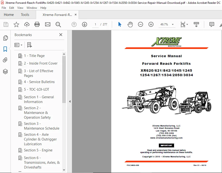
Xtreme Forward Reach Forklifts Xr620 Xr621 Xr842 Xr1045 Xr1245 Xr1254 Xr1267 Xr1534 Xr2050 Xr3034 Service Manual – PDF DOWNLOAD
Original price was: $23.95.$14.95Current price is: $14.95.
Xtreme Forward Reach Forklifts Xr620 Xr621 Xr842 Xr1045 Xr1245 Xr1254 Xr1267 Xr1534 Xr2050 Xr3034 Service Manual
Description
Xtreme Forward Reach Forklifts Xr620 Xr621 Xr842 Xr1045 Xr1245 Xr1254 Xr1267 Xr1534 Xr2050 Xr3034 Service Manual
XTREME FORWARD REACH FORKLIFTS XR620 XR621 XR842 XR1045 XR1245 XR1254 XR1267 XR1534 XR2050 XR3034 SERVICE MANUAL – PDF DOWNLOAD:
IMAGES PREVIEW OF THE MANUAL:


DESCRIPTION:
1-1 SCOPE OF MANUAL: This manual provides operation and maintenance information and procedures intended for use by the owner and/or operator of the forklift. For detailed, specific operating instructions, refer to the applicable Operation and Safety Manual for the specific model forklift. For detailed maintenance and troubleshooting information and schematic diagrams, refer to the Service Manual.
1-2 APPLICABILITY :This Owner’s Service Manual applies to the following model rough-terrain, forward-reach forklifts manufactured by Xtreme Manufacturing: • XR620/621 • XR842 • XR1045 • XR1245 • XR1254 • XR1267 • XR1534 • XR2050 • XR3034
1-3 SERVICE BULLETINS: Service Bulletins are issued by Xtreme Manufacturing, LLC to help mechanics diagnose and repair forklift problems discovered during the manufacturing process or reported by owners and repair shops. There are two types of Service Bulletins: • Safety Service Bulletin: This type of bulletin is issued for safety problems that affect the safe operation of the forklift. An example would be “Parking brake is weak.” • Service Bulletin: This type of bulletin is issued for non-safety problems that affect the reliability or performance of the forklift of forklift subsystem. An example would be “Engine idles rough.” Perform the following steps when you have received a service bulletin: • Carefully read and analyze the service bulletin. • Determine if the service bulletin applies to your forklift(s).
TABLE OF CONTENTS:
Xtreme Forward Reach Forklifts Xr620 Xr621 Xr842 Xr1045 Xr1245 Xr1254 Xr1267 Xr1534 Xr2050 Xr3034 Service Manual
List of Effective Pages A
Service Bulletins B
Table of Contents i
List of Illustrations vi
List of Tables ix
SECTION 1 – GENERAL INFORMATION & SPECIFICATIONS 1-1
1-1 Scope of Manual 1-1
1-2 Applicability 1-1
1-3 Service Bulletins 1-1
1-4 Related Technical Documentation 1-2
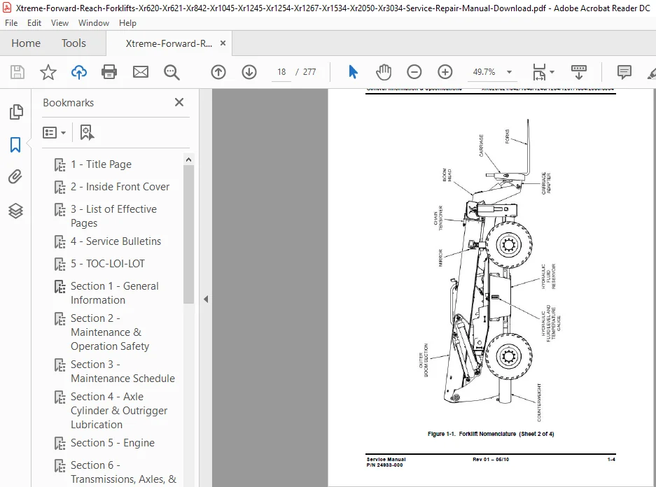
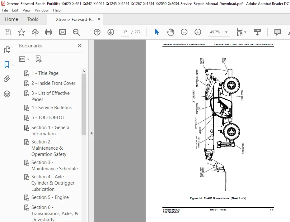
1-5 Forklift Nomenclature 1-2
1-6 Component Data Plates 1-10
1-7 Lubricants and Fluids 1-14
1-8 Filters and Strainers 1-15
1-9 Forklift and Engine Specifications 1-16
1-10 Torque Wrench Use 1-26
1-11 Cap Screw Torque Values 1-27
SECTION 2 – MAINTENANCE & OPERATION SAFETY 2-1
2-1 General 2-1
2-2 Safety Signal Words 2-1
2-3 Notes 2-1
2-4 Safety Symbols 2-2
2-5 Lockout/Tagout Procedure 2-6
2-6 General Maintenance Precautions 2-7
2-7 Viton Seals 2-7
2-8 Using Compressed Air Safely 2-8
2-9 Battery Handling and Maintenance 2-8
2-10 Engine Operation and Maintenance 2-10
2-11 Fuel Handling and Maintenance 2-10
2-12 California Proposition 65 Warnings 2-11
2-13 Functional Tests 2-11
2-14 Safe Operation Checklist 2-12
2-15 Functional Test Checklist 2-13
2-16 Load Handling 2-14
Service Manual Rev 01 – 05/10 i
P/N 24933-000
Table of Contents XR620/621/842/1045/1245/1254/1267/1534/2050/3034
Table of Contents – Cont
PARA TITLE PAGE
2-17 Picking Up a Load 2-16
2-18 Carrying a Load 2-16
2-19 Placing a Load 2-16
2-20 Load Shift 2-17
2-21 Proper Use of Forks 2-17
2-22 Prohibited Practices 2-17
2-23 Operator Hand Signals 2-17
2-24 Safety Decals 2-24
SECTION 3 – MAINTENANCE SCHEDULE 3-1
3-1 Establishing a Preventive Maintenance Program 3-1
3-2 Long-Interval Maintenance Requirements 3-5
SECTION 4 – AXLE CYLINDER AND OUTRIGGER LUBRICATION 4-1
4-1 General Maintenance Safety 4-1
4-2 Using a Grease Gun 4-2
4-3 Lubricate Axle Cylinders and Outriggers 4-3
SECTION 5 – ENGINE 5-1
5-1 General Maintenance Safety 5-1
5-2 Check Engine Oil Level 5-1
5-3 Check Engine Coolant Level 5-3
5-4 Check for Oil and Coolant Leaks 5-6
5-5 Check for Water in Fuel-Water Separator 5-7
5-6 Empty Air Filter Dust Cup 5-9
5-7 Check Condition and Tension of Drive Belts 5-11
5-8 Change Engine Oil 5-11
5-9 Replace Oil Filters 5-14
5-10 Replace Fuel Filter 5-17
5-11 Check Specific Gravity of Coolant 5-19
5-12 Drain and Flush Cooling System 5-22
5-13 Replace Air Filter 5-24
5-14 Check Air Filter 5-25
5-15 Check Condition and Tension of Drive Belts 5-26
5-16 Check and Adjust Valve Tip Clearances 5-28
5-17 Check Engine Hoses and Connections 5-30
Service Manual Rev 01 – 05/10 ii
P/N 24933-000
Table of Contents XR620/621/842/1045/1245/1254/1267/1534/2050/3034
Table of Contents – Cont
PARA TITLE PAGE
5-18 Check Radiator Hoses and Connections 5-31
5-19 Check Engine Wiring and Connections 5-32
5-20 Check for Oil, Coolant, and Fuel Leaks 5-33
SECTION 6 – TRANSMISSION, AXLES, & DRIVE SHAFTS 6-1
6-1 General Maintenance Safety 6-1
6-2 Using a Grease Gun 6-1
6-3 Lubricate Axle Grease Fittings 6-2
6-4 Lubricate Drive Shafts 6-4
6-5 Replace Transmission Filters and Fluids 6-6
6-6 Check Axle Oil Level 6-8
6-7 Check Wheel End Oil Level 6-11
6-8 Drain and Fill Axle Wheel End 6-13
SECTION 7 – WHEELS & TIRES 7-1
7-1 General Maintenance Safety 7-1
7-2 Check Wheel Lug Nut Torque 7-1
7-3 Inspect Wheel/Tire Assembly 7-3
7-4 Replace Wheel/Tire Assembly 7-4
7-5 Replace Tire 7-7
SECTION 8 – HYDRAULIC SYSTEM 8-1
8-1 General Maintenance Safety 8-1
8-2 Hydraulics Maintenance Safety and Precautions 8-1
8-3 Handling Hydraulic Fluid 8-2
8-4 Making Leak-Free Connections 8-2
8-4-1 Hose and Tubing Installation Practices 8-2
8-4-2 Operating Conditions 8-2
8-4-3 Maintenance Practices 8-3
8-5 Keeping the Hydraulic System Clean 8-4
8-6 Check Hydraulic Fluid Level 8-6
8-7 Change Hydraulic Fluid 8-8
8-8 Replace Suction Strainer 8-10
8-9 Clean Hydraulic Reservoir Strainer 8-12
8-10 Replace Air Breather 8-14
8-11 Replace High-Pressure Filter 8-16
8-12 Replace Return Line Filter 8-19
Service Manual Rev 01 – 05/10 iii
P/N 24933-000
Table of Contents XR620/621/842/1045/1245/1254/1267/1534/2050/3034
Table of Contents – Cont
PARA TITLE PAGE
8-13 Taking Hydraulic Fluid Sample 8-21
8-14 Replacing a Hose 8-24
8-15 Tightening Loose Fittings 8-27
8-16 Replace Cartridge Valve 8-27
8-17 Replace Cartridge Valve Solenoid 8-30
8-18 Location of Hydraulic Components 8-32
8-19 Distribution Manifold Hose Connections 8-32
8-20 Maintenance Requirements for Failed Pump 8-47
SECTION 9 – ELECTRICAL SYSTEM 9-1
9-1 General Maintenance Safety 9-1
9-2 Battery Safety 9-1
9-3 Battery Description 9-3
9-4 Battery Cable Description 9-3
9-5 Check Condition of Battery and Cables 9-3
9-6 Replace Battery 9-4
9-7 Inspect and Clean Battery 9-8
9-8 Install Auxiliary Battery 9-10
9-9 Electrical Center Assembly 9-13
9-10 Engine Relay Assembly 9-18
9-11 Replace a Relay 9-20
9-12 Replace a Fuse 9-21
SECTION 10 – BOOM & ATTACHMENTS 10-1
10-1 General Maintenance Safety 10-1
10-2 Using a Grease Gun 10-1
10-3 Boom and Attachment Lubrication 10-2
10-4 Lubricate Boom Extend Chain 10-8
10-5 Inspect Boom Chains 10-9
10-5-1 Chain Nomenclature 10-10
10-5-2 Visually Inspect Chain 10-10
10-5-3 Measure Chain Edge Wear 10-13
10-5-4 Measure Chain Elongation 10-15
10-6 Check and Adjust Boom Chain Tension 10-17
10-7 Slide Blocks 10-18
10-8 Slide Block Inspection 10-18
10-9 Replace Slide Blocks 10-22
Service Manual Rev 01 – 05/10 iv
P/N 24933-000
Table of Contents XR620/621/842/1045/1245/1254/1267/1534/2050/3034
Table of Contents – Cont
PARA TITLE PAGE
10-10 Inspect Boom Rollers 10-23
10-11 Fork Nomenclature 10-27
10-12 Measure Fork Flank Wear 10-29
10-13 Fork Inspection 10-31
10-14 Manually Retracting and Lowering Boom 10-33
SECTION 11 – CHECK-OUT PROCEDURES 11-1
11-1 Check Operation of Rear Axle Stabilization System 12-1
SECTION 12 – STORAGE & TRANSPORTATION 12-1
12-1 General Maintenance Safety 12-1
12-2 Preparing Engine for Long-Term Storage 12-1
12-3 Preparing Forklift for Long-Term Storage 12-4
12-4 Transporting Forklift 12-5
APPENDIX – MAINTENANCE FORMS AND SAFETY TAGS A-1
A-1 Preventive Maintenance and History Logs A-1
A-2 Pre-Operation Checklist A-1
A-3 Safety Tags A-1
Maintenance Schedule A-2
Maintenance History Log A-8
Fork Inspection Log A-11
Pre-Operation Checklist A-13
Grease Fittings List A-15
Danger Tags A-16
Condition Tags A-17
Notes A-18
Service Manual Rev 01 – 05/10 v
P/N 24933-000
Table of Contents XR620/621/842/1045/1245/1254/1267/1534/2050/3034
List of Figures
FIGURE TITLE PAGE
1-1 Forklift Nomenclature 1-3
1-2 Forklift Covers 1-7
1-3 Forklift Cab 1-8
1-4 Front Control Panel 1-9
1-5 Side Control Console 1-10
1-6 Location of Chassis and Engine Data Plates 1-11
1-7 Location of Transmission Data Plates 1-12
1-8 Location of Axle Data Plates 1-13
1-9 SAE Grade 8 Bolt Markings 1-28
2-1 Danger and Condition Tags 2-6
2-2 Battery Disconnect Switch 2-7
2-3 Operator Hand Signals 2-18
2-4 Safety Decals 2-19
3-1 Forklift Hour Meter 3-1
4-1 Front and Rear Axle Cylinder Grease Fittings 4-3
4-2 Outrigger Grease Fittings – XR1245/1254/1267/2050 4-4
5-1 Engine Oil Fill Cap and Dipstick 5-3
5-2 Coolant Level Indicator 5-5
5-3 Radiator 5-5
5-4 Fuel-Water Separator 5-8
5-5 Engine Air Filter Assembly 5-10
5-6 Oil Drain Plug and Dipstick 5-13
5-7 Recommended Engine Oil Viscosity Grades 5-13
5-8 Element-Type Oil Filter 5-15
5-9 Canister-Type Oil Filter 5-16
5-10 Fuel Filter Element 5-18
5-11 Coolant Recovery Tank and Radiator Drain 5-20
5-12 Specific Gravity Chart 5-21
5-13 Cylinder Block Drain Plug 5-23
5-14 Checking Drive Belt Tension 5-27
5-15 Checking and Adjusting Engine Valve Clearances 5-29
5-16 Radiator Hoses and Connections 5-32
Service Manual Rev 01 – 05/10 vi
P/N 24933-000
Table of Contents XR620/621/842/1045/1245/1254/1267/1534/2050/3034
List of Figures – Cont
FIGURE TITLE PAGE
6-1 Axle Grease Fittings 6-3
6-2 Drive Shaft Grease Fittings 6-5
6-3 Transmission Plugs and Filters 6-7
6-4 Axle Differential and Trumpet Fluid Levels 6-10
6-5 Axle Wheel End 6-12
7-1 Lug Nut Torque Check Sequence 7-2
7-2 Wheel/Tire Assembly 7-4
7-3 Wheel Lug Nut Tightening Sequence 7-6
8-1 Making Leak-Free Connections 8-3
8-2 Hydraulic Filtration System 8-5
8-3 Hydraulic Reservoir Sight Gauge 8-7
8-4 Hydraulic Reservoir Fill Cap 8-8
8-5 Hydraulic Reservoir 8-10
8-6 Hydraulic Reservoir Strainer 8-12
8-7 Air Breather 8-15
8-8 Location of Hydraulic Filters 8-17
8-9 High-Pressure Filter 8-18
8-10 Return Line Filter 8-20
8-11 Taking Hydraulic Fluid Sample 8-23
8-12 Hose Installation Guidelines 8-26
8-13 Cartridge Valve Solenoid 8-30
8-14 Location of Hydraulic Components 8-32
8-15 Distribution Manifold Hose Connections – Model XR842 8-37
8-16 Distribution Manifold Hose Connections – Model XR1045 8-39
8-17 Distribution Manifold Hose Connections – Model XR1245 8-41
8-18 Distribution Manifold Hose Connections – Model XR1254 8-43
9-1 Battery and Cables 9-4
9-2 Battery Installation 9-7
9-3 Auxiliary Battery Installation 9-12
9-4 Connecting Auxiliary Battery 9-13
9-5 Electrical Center Relays and Fuses 9-14
9-6 Engine Relay Assembly 9-19
9-7 Correct Installation of Relays B through G, P/N 12068567 9-20
Service Manual Rev 01 – 05/10 vii
P/N 24933-000
Table of Contents XR620/621/842/1045/1245/1254/1267/1534/2050/3034
List of Figures – Cont
FIGURE TITLE PAGE
9-8 Determining Fuse Condition 9-22
10-1 Boom and Attachment Lubrication 10-4
10-2 Boom Extend Chain Lubrication 10-9
10-3 Chain Nomenclature 10-10
10-4 Chain Damage Inspection 10-12
10-5 Chain Edge Wear Measurement 10-14
10-6 Chain Elongation Measurement 10-16
10-7 Boom Chain Tension Adjustment 10-18
10-8 Boom Slide Blocks 10-20
10-9 Boom Roller Inspection 10-24
10-10 Location of Boom Rollers 10-25
10-11 Fork Nomenclature 10-27
10-12 Measuring Fork Flank Wear 10-30
10-13 Boom Lift and Extend Cylinder Manual Lowering Valves 10-34
11-1 Boom Angle Indicator 11-2
11-2 Frame Level Indicator 11-3
12-1 Tie-Down Point Locations 12-6
Service Manual Rev 01 – 05/10 viii
P/N 24933-000
Table of Contents XR620/621/842/1045/1245/1254/1267/1534/2050/3034
List of Tables
TABLE TITLE PAGE
1-1 Related Technical Documentation 1-1
1-2 Lubricants and Fluids 1-14
1-3 Filter and Strainer Part Numbers 1-15
1-4 Model XR620/621 Specifications 1-17
1-5 Model XR842 Specifications 1-17
1-6 Model XR1045 Specifications 1-18
1-7 Model XR1245 Specifications 1-20
1-8 Model XR1254 Specifications 1-21
1-9 Model XR1267 Specifications 1-22
1-10 Model XR1534 Specifications 1-24
1-11 Model XR2050 Specifications 1-25
1-12 Model XR3034 Specifications 1-26
1-13 Engine Specifications 1-28
1-14 Tightening Torque Values – Cap Screws 1-30
2-1 Safety Symbols 2-2
3-1 Preventive Maintenance – After Every 8 Hours of Operation 3-1
3-2 Preventive Maintenance – After First 50 Hours of Operation 3-2
3-3 Preventive Maintenance – After Every 50 Hours of Operation 3-2
3-4 Preventive Maintenance – After Every 250 Hours of Operation 3-3
3-5 Preventive Maintenance – After Every 500 Hours of Operation 3-3
3-6 Preventive Maintenance – After Every 1,000 Hours of Operation 3-4
3-7 Preventive Maintenance – After Every 2,000 Hours of Operation 3-5
3-8 Long-Interval Maintenance Requirements 3-5
5-1 Cylinder and Valve Numbers 5-29
7-1 Forklift Operating Weights 7-5
7-2 Wheel and Tire Specifications 7-7
8-1 Hose Connector Torque Values 8-27
8-2 Boom Isolation Manifold Valve Torque Values 8-45
8-3 Rear Axle Cylinder Valve Torque Values 8-45
8-4 Distribution Manifold Torque Values (XR842/1045) 8-45
8-5 Distribution Manifold Torque Values (XR1245/1254) 8-46
9-1 Electrical Center Relays 9-17
9-2 Electrical Center Fuses and Circuit Breaker 9-17
Service Manual Rev 01 – 05/10 ix
P/N 24933-000
Table of Contents XR620/621/842/1045/1245/1254/1267/1534/2050/3034
Service Manual Rev 01 – 05/10 x
P/N 24933-000
List of Tables – Cont
TABLE TITLE PAGE
9-3 Fuse Block Fuses 9-18
9-4 Engine Relay Assembly Relays and Fuse 9-18
10-1 Fork Nomenclature 10-27
12-1 Forklift Operating Weights 12-5
INDEX DETAILS:
Xtreme Forward Reach Forklifts Xr620 Xr621 Xr842 Xr1045 Xr1245 Xr1254 Xr1267 Xr1534 Xr2050 Xr3034 Service Manual
- Adjusting Engine Valve Clearances, Checking
- Air Breather
- Air Breather, Replacing
- Air Filter Assembly, Engine
- Air Filter Dust Cup, Emptying
- Air Filter, Checking
- Air Filter, Replacing
- Applicability of Manual
- Auxiliary Battery Installation
- Auxiliary Battery, Connecting
- Auxiliary Battery, Installing
- Axle Cylinder and Outrigger Lubrication
- Axle Cylinders and Outriggers, Lubrication
- Axle Data Plates, Location
- Battery and Cables
- Battery and Cables, Checking Condition
- Battery Cable Description
- Battery Description
- Battery Disconnect Switch
- Battery Handling and Maintenance
- Battery Installation
- Battery Safety
- Battery, Inspecting and Cleaning
- Battery, Replacing
- Boom & Attachments
- Boom and Attachment Lubrication
- Boom and Attachment Lubrication
- Boom Angle Indicator
- Boom Chain Tension Adjustment
- Boom Chain Tension, Checking and Adjusting
- Boom Chains, Inspecting
- Boom Extend Chain Lubrication
- Boom Extend Chain, Lubrication
- Boom Isolation Manifold Valve Torque Values
- Boom Lift and Extend Cylinder Manual Lowering Valves
- Boom Roller Inspection
- Boom Rollers, Inspecting
- Boom Rollers, Location
- Boom Slide Blocks
- California Proposition Warnings
- Canister Type Oil Filter
- Cap Screw Torque Values
- Carrying a Load
- Cartridge Valve Solenoid
- Cartridge Valve Solenoid, Replacing
- Cartridge Valve, Replacing
- Chain Damage Inspection
- Chain Edge Wear Measurement
- Chain Edge Wear, Measuring
- Chain Elongation Measurement
- Chain Elongation, Measuring
- Chain Nomenclature
- Chain, Visually Inspecting
- Service Manual Rev – / Index P/N
- Index XR
- Chassis and Engine Data Plates, Location
- Check Condition and Tension of Drive Belts
- Check Engine Coolant Level
- Check for Water in FuelWater Separator
- CheckOut Procedures
- Component Data Plates
- Condition Tags
- Coolant Level Indicator
- Coolant Recovery Tank and Radiator Drain
- Cooling System, Drain and Flush
- Cylinder and Valve Numbers
- Cylinder Block Drain Plug
- Danger and Condition Tags
- Danger Tags
- Distribution Manifold Torque Values (XR/)
- Distribution Manifold Torque Values (XR/)
- Drive Belt Condition and Tension, Checking
- Drive Belt Tension, Checking
- – E –
Electrical Center Assembly - Electrical Center Fuses and Circuit Breaker
- Electrical Center Relays
- Electrical Center Relays and Fuses
- Electrical System
- Engine
- Engine Hoses and Connections, Checking
- Engine Oil Level, Checking
- Engine Oil, Changing
- Engine Operation and Maintenance
- Engine Specifications
- Engine Wiring and Connections, Checking
- Filter and Strainer Part Numbers
- Filter, HighPressure
- Filters and Strainers
- Fork Flank Wear, Measuring
- Fork Inspection
- Fork Inspection Log
- Fork Nomenclature
- Forklift and Engine Specifications
- Forklift Cab
- Forklift Covers
- Forklift Hour Meter
- Forklift Nomenclature
- Forklift Operating Weights
- Frame Level Indicator
- Front Control Panel
- Fuel Filter Element
- Fuel Filter, Replacing
- Fuel Handling and Maintenance
- FuelWater Separator
- Functional Test Checklist
- Functional Tests
- Fuse Block Fuses
- Fuse Condition
- Fuse, Replacing
- General
- General Information & Specifications
- General Maintenance Precautions
- General Maintenance Safety
- Grease Fittings List
- Handling Hydraulic Fluid
- Service Manual Rev – / Index
- HighPressure Filter
- HighPressure Filter, Replacing
- Hose and Tubing Installation Practices
- Hose Connector Torque Values
- Hose Installation Guidelines
- Hose, Replacing
- Hydraulic Components, Location
- Hydraulic Filtration System
- Hydraulic Fluid Level, Checking
- Hydraulic Fluid, Changing
- Hydraulic Reservoir
- Hydraulic Reservoir Fill Cap
- Hydraulic Reservoir Sight Gauge
- Hydraulic Reservoir Strainer
- Hydraulic Reservoir Strainer, Cleaning
- Hydraulic System
- Hydraulics Maintenance Safety and Precautions
- Keeping the Hydraulic System Clean
- List of Effective Pages
- List of Illustrations
- List of Tables
- Load Handling
- Load Shift
- Location of Hydraulic Filters
- Lockout/Tagout Procedure
- Lubricants and Fluids
- Lug Nut Torque Check Sequence
- Maintenance & Operation Safety
- Maintenance Forms & Safety Tags
- Maintenance History Log
- Maintenance Practices
- Maintenance Requirements for Failed Pump
- Maintenance Requirements, LongInterval
- Maintenance Schedule
- Making LeakFree Connections
- Manually Retracting and Lowering Boom
- Model XR Specifications
- Model XR Specifications
- Model XR Specifications
- Model XR Specifications
- Oil and Coolant Leaks, Checking
- Oil Drain Plug and Dipstick
- Oil Fill Cap and Dipstick, Engine
- Oil Filter, ElementType
- Oil Filters, Replacing
- Oil, Coolant, and Fuel Leaks, Checking
- Operating Conditions
- Operator Hand Signals
- Outrigger Grease Fittings – XR/
- – P –
Picking Up a Load - Placing a Load
- PreOperation Checklist
A, A
Preparing Engine for LongTerm Storage - Preparing Forklift for LongTerm Storage
- Service Manual Rev – / Index
P/N
Index XR/////////
Preventive Maintenance – After Every , Hours of Operation - Preventive Maintenance – After Every , Hours of Operation
- Preventive Maintenance – After Every Hours of Operation
- Preventive Maintenance – After Every Hours of Operation
- Preventive Maintenance – After Every Hours of Operation
- Preventive Maintenance – After Every Hours of Operation
- Preventive Maintenance – After First Hours of Operation
- Preventive Maintenance and History Logs
A
Preventive Maintenance Program, Establishing - Prohibited Practices
- Proper Use of Forks
- – Q –
– R –
Radiator - Radiator Hoses and Connections
- Radiator Hoses and Connections, Checking
- Rear Axle Cylinder Grease Fittings
- Rear Axle Cylinder Valve Torque Values
- Rear Axle Stabilization System, Checking Operation
- Recommended Engine Oil Viscosity Grades
- Related Technical Documentation
- Relay Assembly Relays and Fuse, Engine
- Relay Assembly, Engine
,
Relay, Replacing - Relays B through G, P/N , Correct Installation
- Return Line Filter, Replacing
- Return Line Filter
- – S –
SAE Grade Bolt Markings - Safe Operation Checklist
- Safety Labels
- Safety Signal Words
- Safety Symbols
- Safety Tags
- Scope of Manual
- Service Bulletins
- Service Bulletins
- Side Control Console
- Slide Block Inspection
- Slide Blocks
- Slide Blocks, Replacing
- Specific Gravity Chart
- Specific Gravity of Coolant, Checking
- Storage & Transportation
- Suction Strainer, Replacing
- Taking Hydraulic Fluid Sample
- TieDown Point Locations
- Tightening Loose Fittings
- Tightening Torque Values – Cap Screws
- Tire, Replacing
- Torque Wrench Use
- Transmission Data Plates, Location
- Transporting Forklift
- Using a Grease Gun
- Using Compressed Air Safely
- Service Manual Rev – / Index
- Valve Tip Clearances, Checking and Adjusting
- Viton Seals
- Wheel Lug Nut Tightening Sequence
- Wheel Lug Nut Torque, Checking
- Wheel/Tire Assembly
- Wheel/Tire Assembly, Inspecting
- Wheel/Tire Assembly, Replacing
- Wheels & Tires
FILE DETAILS:
LANGUAGE:ENGLISH
PAGES:277
DOWNLOADABLE:YES
FILE TYPE:PDF
PLEASE NOTE:
- This is the same manual used by the DEALERSHIPS to SERVICE your vehicle.
- The manual can be all yours – Once payment is complete, you will be taken to the download page from where you can download the manual. All in 2-5 minutes time!!
- Need any other service / repair / parts manual, please feel free to contact us at heydownloadss @gmail.com . We may surprise you with a nice offer
Aldo Adan –
GREAT SERVICE AS ALWAYS