★ TRUSTED BY 321,897+ PROFESSIONALS WORLDWIDE
🏢
Trusted Business
Verified & Licensed
🛡️
Virus Free Files
100% Safe Downloads
🔒
Secure Payment
SSL Protected
Instant Delivery
Available Immediately
Sale!

Xtreme XR1055 Telehandler Parts Manual – Complete Illustrated Parts Catalog PDF

Original price was: $39.95.Current price is: $24.95.

686-page illustrated parts manual for the Xtreme XR1055 telehandler, covering 74HP and 120HP Cummins models with exploded diagrams and bill-of-material tables for every assembly.

Instant PDF Download
Available immediately
💾
Save to Your Device
Download & keep forever
🛡️
Antivirus Scanned
100% virus-free
🌍
Trusted Worldwide
175,000+ customers

Description

Xtreme XR1055 Telehandler Parts Manual – Complete Illustrated Parts Catalog

This is the complete illustrated parts manual for the Xtreme XR1055 telehandler, covering both the 74HP and 120HP Cummins-powered variants. With 686 pages of detailed exploded-view diagrams and corresponding bill-of-material tables, this parts catalog gives you every component number, quantity, and description needed to identify, order, and replace parts on your machine. Whether you are maintaining a single XR1055 or managing a fleet, this manual is the definitive reference for every assembly on the machine.

What This Parts Manual Covers

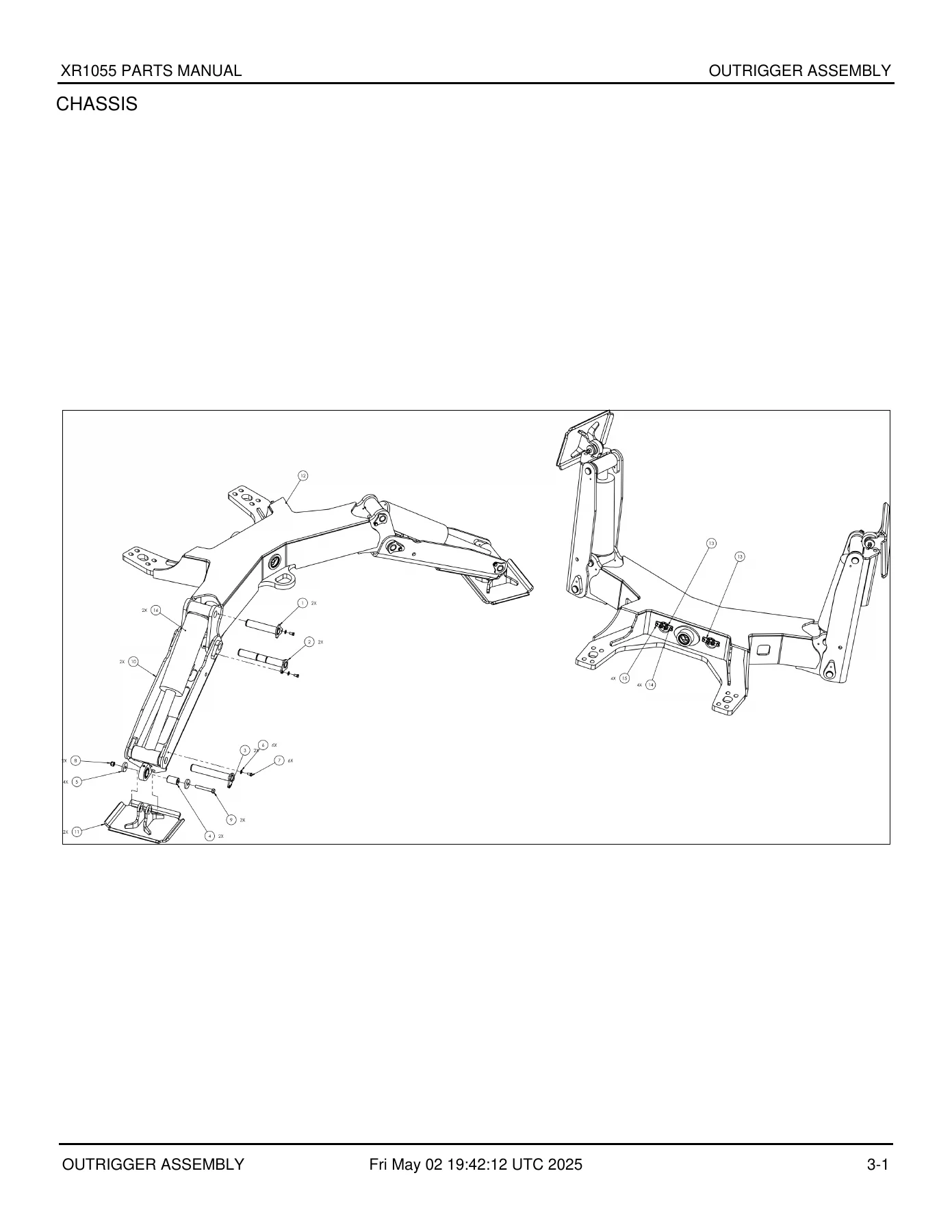
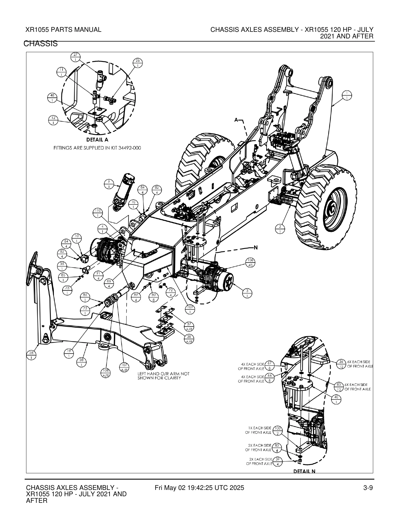
The manual is organized into major system groups, each containing detailed exploded drawings with balloon callouts that cross-reference directly to a parts table. The table lists item number, Xtreme part number, quantity, and description for every component shown. This structure makes it straightforward to locate any part on the machine, from a simple washer to a complete boom assembly.

Component Identification

The manual opens with a component identification section that maps out the major systems and assemblies across the XR1055. This gives you a quick visual reference to understand how the machine is broken down and where each system-specific section begins.

Chassis

The chassis section is extensive, covering the outrigger assembly, outrigger mount, outrigger leg, outrigger bulkhead, and the complete chassis assembly for both engine configurations. Separate sections cover the Tier 4 Final 72HP XR1055 (June 2021 and before), the 72HP July 2021 and after variant, the T4F 120HP (June 2021 and before), and the 120HP July 2021 and after variant. You will find detailed breakdowns of:

  • Outrigger assembly, mount, leg, and bulkhead components
  • Chassis axles assembly for both 72HP and 120HP configurations
  • Engine mounting and chassis assembly – engine T4F 120HP
  • Chassis covers for both 74HP and 120HP machines, with separate sections for pre- and post-July 2021 builds
  • Hydraulic/fuel tank assembly and purchased components
  • Chassis hose kits for both 74HP and 120HP engines

Boom

The boom section covers every component of the telescopic boom assembly, including the outer boom, outer mid boom, inner int boom, and inner boom assemblies. You will also find detailed breakdowns for:

  • Boom assembly for November 2021 and before, and December 2021 and after
  • Boom support assembly
  • Roller pin, mid roller assembly, intermediate roller assembly, and roller assemblies in multiple sizes
  • Outer boom roller, inner boom roller, outer chain sheave, and chain sheave assemblies
  • Extend cylinder, tilt cylinder, and adapter assemblies
  • Slide blocks, shims, and spacers for boom wear surfaces
  • Chain tensioners, chain pins, and chain assemblies

Engine

The engine section covers the complete engine and transmission assembly for both the Cummins 74HP 3.8 with ZF transmission and the Cummins 120HP 3.8 with XR1055 transmission. Detailed coverage includes:

  • Engine/transmission assembly – Cummins 74HP 3.8 – ZF
  • Engine/transmission assembly – Cummins 120HP 3.8 – XR1055
  • Extended exhaust pipe
  • Radiator
  • Air shut off valve installation for the 3.8 Cummins
  • Air cleaner assembly and air intake connections
  • ECM mount bracket assembly

Cabin & Covers

The cabin and covers section provides complete parts coverage for both open and enclosed cab configurations, including:

  • Cab mounting for open cab T4F, enclosed cab T4F, and enclosed cab with A/C T4F
  • Open cab assembly for 74HP models
  • Enclosed cab assembly and enclosed cab with A/C assembly
  • Cab assembly for ZF models with outriggers (February 2021 and after) in open, enclosed, and enclosed with A/C configurations
  • Enclosed cab weldment for B-Series
  • Seat assembly, arm rest, and accelerator pedal assembly
  • Front cover assembly, front cover frame assembly, and front cover with doors assembly
  • Cover kits for 74HP and 120HP XR1055/XR1147 models
  • Engine cover assembly for 74HP and 120HP, sliding engine cover kit, rear cover assembly, cooler cover assembly, battery cover assembly, and DEF cover assembly

Hydraulic System

The hydraulic system section is one of the largest in the manual, covering every pump, valve, cylinder, and manifold on the machine. Component coverage includes:

Complete PDF Bookmark Tree

Complete Bookmarks

The complete bookmarks in the “Xtreme XR1055 Telehandler Parts Manual – Complete Illustrated Parts Catalog PDF” are as follows:

GENERAL INFORMATIONp. 8
XR1055 GENERAL INFORMATIONp. 8
COMPONENT IDENTIFICATIONp. 12
XR1055 COMPONENT IDENTIFICATIONp. 12
CHASSISp. 13
OUTRIGGER ASSEMBLYp. 13
OUTRIGGER MOUNT ASSEMBLYp. 15
OUTRIGGER LEG ASSEMBLYp. 17
OUTRIGGER BULKHEAD ASSEMBLYp. 19
CHASSIS ASSEMBLY – ENGINE T4F 120HP CUp. 21
CHASSIS ASSEMBLY – AXLES TIER 4 FINAL 72HP XR1055 – JUNE 2021 AND BEFOREp. 29
CHASSIS AXLES ASSEMBLY – XR1055 72 HP – JULY 2021 AND AFTERp. 41
CHASSIS ASSEMBLY – AXLES – XR1055 T4F 120 HP – JUNE 2021 AND BEFOREp. 53
CHASSIS AXLES ASSEMBLY – XR1055 120 HP – JULY 2021 AND AFTERp. 62
CHASSIS – ENGINE – 120HP CUMMINSp. 71
CHASSIS ASSEMBLY – ENGINE – T4F XR1055 – JUNE 2021 AND BEFOREp. 79
CHASSIS ASSEMBLY ENGINE – T4F XR1055 – JULY 2021 AND AFTERp. 89
CHASSIS ASSEMBLY – COVER TIER 4 FINAL – XR1055 – JUNE 2021 AND BEFOREp. 99
CHASSIS ASSEMBLY COVER – X1055 – T4F – JULY 2021 AND AFTERp. 103
CHASSIS ASSEMBLY – COVERS – 120 HP XR1055 – JUNE 2021 AND BEFOREp. 107
CHASSIS ASSEMBLY – COVERS 120HP – XR1055 – JULY 2021 AND AFTERp. 111
HYDRAULIC/FUEL TANK ASSEMBLYp. 118
HYDRAULIC/FUEL TANK PURCHASED ASSEMBLYp. 121
HYDRAULIC/FUEL TANK ASSEMBLY – 120HPp. 123
CHASSIS HOSE KIT – XR1055 – T4F-C – 74HPp. 127
CHASSIS HOSE KIT – XR 1055 120HPp. 131
BOOMp. 139
BOOM ASSEMBLY – NOVEMBER 2021 AND BEFOREp. 139
BOOM ASSEMBLY – DECEMBER 2021 AND AFTERp. 148
OUTER BOOM ASSEMBLYp. 158
OUTER MID BOOM ASSEMBLYp. 160
INNER INT BOOM ASSEMBLY – XR1055p. 165
INNER BOOM ASSEMBLYp. 169
BOOM SUPPORT ASSEMBLY – XR1055p. 172
ROLLER PINp. 174
MID ROLLER ASSEMBLYp. 176
INTERMEDIATE ROLLER ASSEMBLYp. 178
ROLLER ASSEMBLY – 4.50 OD x 3.00 IDp. 180
ROLLER ASSEMBLYp. 182
OUTER BOOM ROLLER ASSEMBLYp. 184
INNER BOOM ROLLER ASSEMBLYp. 186
OUTTER CHAIN SHEAVE ASSEMBLYp. 188
CHAIN SHEAVE ASSEMBLYp. 190
CHAIN SHEAVE ASSEMBLYp. 192
INNER CHAIN SHEAVE ASSEMBLYp. 194
SLIDE BLOCK ASSEMBLYp. 196
SLIDE BLOCK ASSEMBLYp. 198
SLIDE BLOCK ASSEMBLY – EXTEND TUBEp. 200
ADAPTER ASSEMBLYp. 202
TUBE CLAMP ASSEMBLY #2p. 204
HOSE CLAMP ASSEMBLYp. 206
ANGLE INDICATOR ASSEMBLYp. 208
TRANSDUCER MOUNT – BASE ASSEMBLYp. 210
TRANSDUCER MOUNT – TIP ASSEMBLYp. 212
MAGNET – COORDINATED MOTION ASSEMBLYp. 214
ENGINEp. 216
ENGINE/TRANSMISSION ASSEMBLY – CUMMINS 74HP 3.8 – ZFp. 216
ENGINE/TRANSMISSION ASSEMBLY – CUMMINS 120 HP 3.8 – XR1055p. 220
EXTENDED EXHAUST PIPE – XR1055 12HPp. 224
RADIATORp. 226
AIR SHUT OFF VALVE INSTALLATION – 3.8 CUMMINSp. 227
AIR CLEANER ASSEMBLY – CUMMINSp. 230
AIR INTAKE CONNECTIONp. 232
AIR INTAKE CONNECTIONp. 234
BRACKET ASSEMBLY – ECM MOUNT – CUMMINSp. 236
CABIN & COVERSp. 238
CAB MOUNTING XR1055 OPEN CAB T4Fp. 238
CAB MOUNTING XR1055 ENCLOSED CAB T4Fp. 241
CAB MOUNTING XR1055 ENCLOSED CAB W/AC T4Fp. 244
CAB MOUNTING OPEN CAB – XR1055 – ZF – 120 HPp. 247
OPEN CAB ASSEMBLY – XR1055 – 74HPp. 250
CAB ENCLOSED ASSEMBLY – XR1055- 74HPp. 256
CAB ENCLOSED W/AC ASSEMBLY XR1055 74hpp. 262
CAB ASSEMBLY OPEN ZF W/OUTRIGGERS – FEBRUARY 2021 AND AFTERp. 268
CAB ASSEMBLY ENCLOSED ZF W/OUTRIGGERS – FEBRUARY 2021 AND AFTERp. 274
CAB ASSEMBLY ENCLOSED W/AC ZF W/OUTRIGGERS – FEBRUARY 2021 AND AFTERp. 280
ENCLOSED CAB WELDMENT – B-SERIESp. 286
SEAT ASSEMBLYp. 290
ARM REST – ADJUSTABLE – ASSEMBLYp. 292
ACCELERATOR PEDAL ASSEMBLYp. 294
FRONT COVER ASSEMBLYp. 296
FRONT COVER ASSEMBLYp. 298
FRONT COVER FRAME ASSEMBLYp. 300
FRONT COVER W/DOORS ASSEMBLYp. 302
COVERS KIT – 74 HP – XR1055/XR1147p. 304
COVERS KIT – 120 HP – XR1055/XR1147p. 307
COVERS ASSEMBLY – ENGINE 74HPp. 310
ENGINE COVER ASSEMBLY – 74HPp. 312
ENGINE COVER ASSEMBLYp. 314
HOOD BRACKET ASSEMBLYp. 316
ENGINE COVER ASSEMBLY – RH SIDEp. 318
SLIDING ENGINE COVER KIT – XR843/XR944/XR1055/XR1147p. 320
REAR COVER ASSEMBLYp. 325
REAR COVER ASSEMBLY – 120HPp. 327
COOLER COVER ASSEMBLYp. 329
COOLER COVER ASSEMBLYp. 331
COVERS ASSEMBLY – ENGINE 120 HPp. 333
COOLER COVER ASSEMBLY – 120 HPp. 335
COOLER ASSEMBLY COVERp. 337
BATTERY COVER ASSEMBLYp. 339
COVER ASSEMBLY – CUMMINS DEF 120 HPp. 341
HYDRAULIC SYSTEMp. 343
HYDRAULIC PUMP ASSEMBLY – HENGLIp. 343
PUMP SEALS SERVICE KIT – HYDRAULIC PUMP – HENGLIp. 348
HIGH-PRESSURE FILTER/STEERING VALVE ASSEMBLYp. 350
STEERING VALVE/HIGH PRESSURE FILTER ASSEMBLYp. 352
CONTROL VALVE ASSEMBLY – HYDRAULIC PUMP – HENGLIp. 355
FORK POSTITION VALVEp. 358
BRAKE/STEER MANIFOLD ASSEMBLYp. 360
BOOM MANIFOLD ASSEMBLYp. 367
BOOM MANIFOLD ASSEMBLY – LHp. 369
BOOM MANIFOLD ASSEMBLY – RHp. 371
HENGLI OUTRIGGER CYLINDER ASSEMBLYp. 373
VALVE MAIN CONTROL – HAWEp. 375
VALVE MAIN CONTROL ASSEMBLYp. 377
14170-200 CONTROL VALVEp. 381
REAR AXLE LOCK MANIFOLD ASSEMBLYp. 382
MASTER CYLINDER ASSEMBLY – 2.75Bp. 384
MASTER CYLINDER PIN ASSEMBLYp. 386
MASTER CYLINDER PIN ASSEMBLYp. 388
LIFT CYLINDER ASSEMBLYp. 390
LIFT CYLINDER PIN ASSEMBLYp. 392
EXTEND CYLINDER ASSEMBLYp. 394
EXTEND CYLINDER SUB-ASSEMBLYp. 397
EXTEND CYLINDER HOUSING ASSEMBLYp. 399
EXTEND CYLINDER COLLAR ASSEMBLYp. 401
EXTEND CYLINDER SUPPORT ASSEMBLYp. 403
CARRIAGE TILT CYLINDER ASSEMBLYp. 405
FRONT SWAY CYLINDER ASSEMBLYp. 407
REAR SWAY CYLINDER ASSEMBLYp. 409
OUTRIGGER CYLINDER ASSEMBLY – HENGLIp. 411
TILT CARRIAGE FITTING KITp. 413
BOOM HOSE KIT – HIGH PIVOT ROLLER BOOM – XR1055p. 415
BOOM HOSE KITp. 417
BOOM FITTING KITp. 419
HYDRAULIC SCHEMATIC – 1055p. 421
ELECTRICAL SYSTEMp. 422
BATTERY DISCONNECT SWITCH ASSEMBLYp. 422
KIEWIT LHP TELEMATICS HARNESSp. 424
ENGINE HARNESS – 74HP CUMMINS 3.8p. 427
ENGINE HARNESS – CUMMINS 3.8L 120HPp. 431
TRANSMISSION HARNESS – ZF – XR1055p. 439
WINDSHIELD WIPER HARNESSp. 440
ELECTRICAL ACCESS PANEL ASSEMBLYp. 442
WIPER WIRING LAYOUTp. 445
SWITCH PANEL ASSEMBLYp. 447
SWITCH PANEL ASSEMBLY NO OUTRIGGERSp. 450
JOYSTICK PG CAN I/O HARNESSp. 453
SWAY JOYSTICK ASSEMBLYp. 457
JOYSTICK ASSEMBLY – DUAL AXISp. 459
ASSY, GT JOYSTICK SWAYp. 461
STRIP TERMINAL ASSEMBLY #8 X 12p. 463
STRIP TERMINAL ASSEMBLY #6 X 12p. 465
LIGHT MOUNT ASSEMBLYp. 467
LIGHT – RED LED ASSEMBLYp. 469
REAR LIGHT ASSEMBLYp. 471
ELECTRICAL SCHEMATIC – XR1055 74HPp. 473
ELECTRICAL SCHEMATIC – XR1055 120HPp. 474
TRANSMISSION, AXLES & DRIVESHAFTSp. 475
OUTPUT ASSEMBLY – ZFp. 475
FRONT AXLE ASSEMBLY – ZFp. 477
REAR AXLE ASSEMBLY – ZFp. 479
AXLE CASING ASSEMBLY – ZFp. 481
LIMIT SLIP DIFFERENTIAL ASSEMBLY – FRONT AXLE – ZFp. 483
JOINT HOUSING ASSEMBLY – FRONT AXLE – ZFp. 485
INPUT ASSEMBLY – FRONT AXLE – ZFp. 487
JOINT HOUSINGp. 493
JOINT HOUSING ASSEMBLY – ZFp. 495
PLANETARY DRIVE ASSEMBLY – ZFp. 498
PLANETARY DRIVE ASSEMBLY – ZFp. 500
INPUT ASSEMBLY – ZFp. 502
DIFFERENTIAL ASSEMBLY – ZFp. 508
TRANSMISSION AND PUMP ASSEMBLY – ZFp. 510
STEERING LIMITER – FRONT/REAR AXLEp. 512
STEER STOP ASSEMBLY KITp. 514
TRANSMISSION ASSEMBLY – 120 HP – XR1055p. 516
TRANSMISSION FILTER ASSEMBLYp. 518
COLD WEATHER INSTALLATION TRANSMISSION – ZF – 120HPp. 520
INSTALLATION TRANSMISSION BYPASS VALVE – CUMMINS 74HPp. 523
TRANSMISSION THERMAL BYPASS – ZFp. 525
STEERING, BRAKES, TIRES & WHEELSp. 527
STEERING CYLINDERp. 527
BRAKE VALVE ASSEMBLY – MICOp. 529
MICO BRAKE PEDAL KIT ASSEMBLY – XR1045/XR2045p. 531
MULTI-DISK BRAKE REAR AXLEp. 533
MULTI-DISK BRAKE ASSEMBLY – ZFp. 535
PARKING BRAKEp. 537
REAR ACCUMULATOR ASSEMBLYp. 539
BRAKE CHARGE VALVE ASSEMBLYp. 541
STEERING COLUMN ASSEMBLYp. 544
LABELSp. 546
LABEL KITp. 546
ATTACHMENTSp. 551
STANDARD CARRIAGE ASSEMBLY HEAVY-DUTY WITH DOUBLERSp. 551
CARRIAGE STANDARD HEAVY DUTY ASSEMBLYp. 553
72" CARRIAGE ASSEMBLY – ADJUSTABLE FORKS – 12Kp. 555
48" GROUP B TILT CARRIAGE ASSEMBLYp. 557
48'' GRP B FORK POSITIONp. 559
60" CARRIAGE ASSEMBLY -12K ADJUSTABLE FORKSp. 563
96'' DIRECT PIN ADJUSTABLE CARRIAGE ASSEMBLYp. 565
CARRIAGE PIN ASSEMBLYp. 570
HITCH PIN ASSEMBLYp. 572
OPTIONSp. 574
OPTION – FIRE EXTINGUISHER INSTALLATIONp. 574
OPTION – TELEMATICS – XR742/XR843/XR944/XR1055/XR1147/XR1255-B/XR1347/XR1555/XR1734p. 576
LMI DOVER TWG KITp. 578
OPTION – SMV SIGNp. 580
OPTION – SMV SIGNp. 582
OPTION – BOOM LIGHTS W/CABLE REELp. 584
OPTION – REAR CAMERA FOR XR1055/XR1147/XR1247p. 587
AUXILIARY CAMERA INSTALLATIONp. 589
BREATHER HEATER INSTALLATION – 3.8 CUMMINSp. 591
PROPORTIONAL AUX JOYSTICK ASSEMBLYp. 593
OPTION – FLASHING AMBER STROBEp. 595
OPTION – ROTATING AMBER BEACONp. 597
OPTION – SECONDARY SEATBELT SWITCH BEACONp. 599
OPTION – AMBER BEACON AND SECONDARY SEATBELT BEACONp. 601
OPTION – CAB WORK LIGHTSp. 603
ENCLOSED CAB WORK LIGHTSp. 605
FENDERS – 13 X 24 TIRES – ZFp. 607
OPTION – SOLID TIRES 14 X 24 CAMSO TLH NON-MARKING TIRESp. 609
OPTION – FENDER – KR1055/1147p. 611
OPTION – SOLARGIZER 12V – ALDENp. 613
COORDINATED BOOM OPTION XR1055p. 617
OPTION – ENCLOSED CAB WITH AC WITH CLEAR GLASSp. 622
AUXILIARY HEATER INSTALLATION – ENCLOSED CABp. 628
OPTION – WHITE NOISE ALARM – XR1055p. 632
OPTION – TELEMATICS KEYPAD – XR742/XR843/XR944/XR1055/XR1147/XR1255-B/XR1347/XR1547/XR1555/XR1734p. 634
OPTION – SLOW MOVING VEHICLE SIGNp. 637
OPTION – BOOM LIGHTS ASSEMBLYp. 639
TAIL/TURN OPTION CHASSIS MOD XR1055 HIGH PIVOT ROLLER BOOMp. 642
OPTION – BOOM LIGHTS W/CABLE REEL – XR1055p. 645
OPTION – FLASHING GREEN STROBEp. 648
REAR WIPER MOTOR KITp. 650
Annexe A :Index des pagesp. 652
Annexe B :Index des piècesp. 657

  • Hydraulic pump assembly – Hengli, and pump seals service kit
  • High-pressure filter/steering valve assembly and steering valve/high pressure filter assembly
  • Control valve assembly – hydraulic pump – Hengli
  • Fork position valve
  • Brake/steer manifold assembly
  • Boom manifold assembly (LH and RH)
  • Hengli outrigger cylinder assembly
  • Valve main control – Hawe, and valve main control assembly
  • 14170-200 control valve
  • Rear axle lock manifold assembly
  • Master cylinder assembly, master cylinder pin assemblies
  • Lift cylinder assembly and lift cylinder pin assembly
  • Extend cylinder assembly, sub-assembly, housing assembly, collar assembly, and support assembly
  • Carriage tilt cylinder assembly
  • Front sway cylinder assembly, rear sway cylinder assembly
  • Outrigger cylinder assembly – Hengli

Electrical System

The electrical section covers the complete wiring and control system, including:

  • Battery disconnect switch assembly
  • Kiewit LHP telematics harness
  • Engine harness for 74HP Cummins 3.8 and Cummins 3.8L 120HP
  • Transmission harness – ZF – XR1055
  • Windshield wiper harness
  • Electrical access panel assembly
  • Wiper wiring layout
  • Switch panel assembly and switch panel assembly no outriggers
  • Joystick PG CAN I/O harness
  • Sway joystick assembly
  • Joystick assembly – dual axis
  • GT joystick sway assembly
  • Strip terminal assemblies
  • Light mount assembly, red LED light assembly, and rear light assembly
  • Electrical schematic for XR1055 74HP and XR1055 120HP

Transmission, Axles & Driveshafts

This section covers the drivetrain components including:

  • Output assembly – ZF
  • Front axle assembly – ZF and rear axle assembly – ZF
  • Axle casing assembly – ZF
  • Limit slip differential assembly – front axle – ZF
  • Joint housing assemblies
  • Input assemblies
  • Planetary drive assemblies – ZF
  • Differential assembly – ZF
  • Transmission and pump assembly – ZF
  • Steering limiter and steer stop assembly kit
  • Transmission filter assembly
  • Cold weather installation transmission – ZF – 120HP
  • Transmission bypass valve installation – Cummins 74HP
  • Transmission thermal bypass – ZF

Steering, Brakes, Tires & Wheels

Coverage includes the steering cylinder, brake valve assembly – Mico, Mico brake pedal kit assembly, multi-disk brake rear axle, multi-disk brake assembly – ZF, parking brake, rear accumulator assembly, brake charge valve assembly, and steering column assembly.

Labels

The label kit section provides part numbers for all safety and informational decals used on the XR1055, including data plates, dash overlays, danger/warning/caution labels, boom lettering, logos, and load charts.

Attachments

Attachment coverage includes standard carriage assembly heavy-duty with doublers, carriage standard heavy-duty assembly, 72″ carriage assembly with adjustable forks, 48″ Group B tilt carriage assembly, 48″ Group B fork position, 60″ carriage assembly with 12K adjustable forks, 96″ direct pin adjustable carriage assembly, carriage pin assembly, and hitch pin assembly.

Options

The options section covers factory and dealer-installed accessories including fire extinguisher installation, telematics for multiple XR models, LMI Dover TWG kit, SMV sign options, boom lights with cable reel, rear camera for XR1055/XR1147/XR1247, auxiliary camera installation, breather heater installation for 3.8 Cummins, proportional aux joystick assembly, flashing amber strobe, rotating amber beacon, and secondary seatbelt switch beacon options.

IMAGES PREVIEW

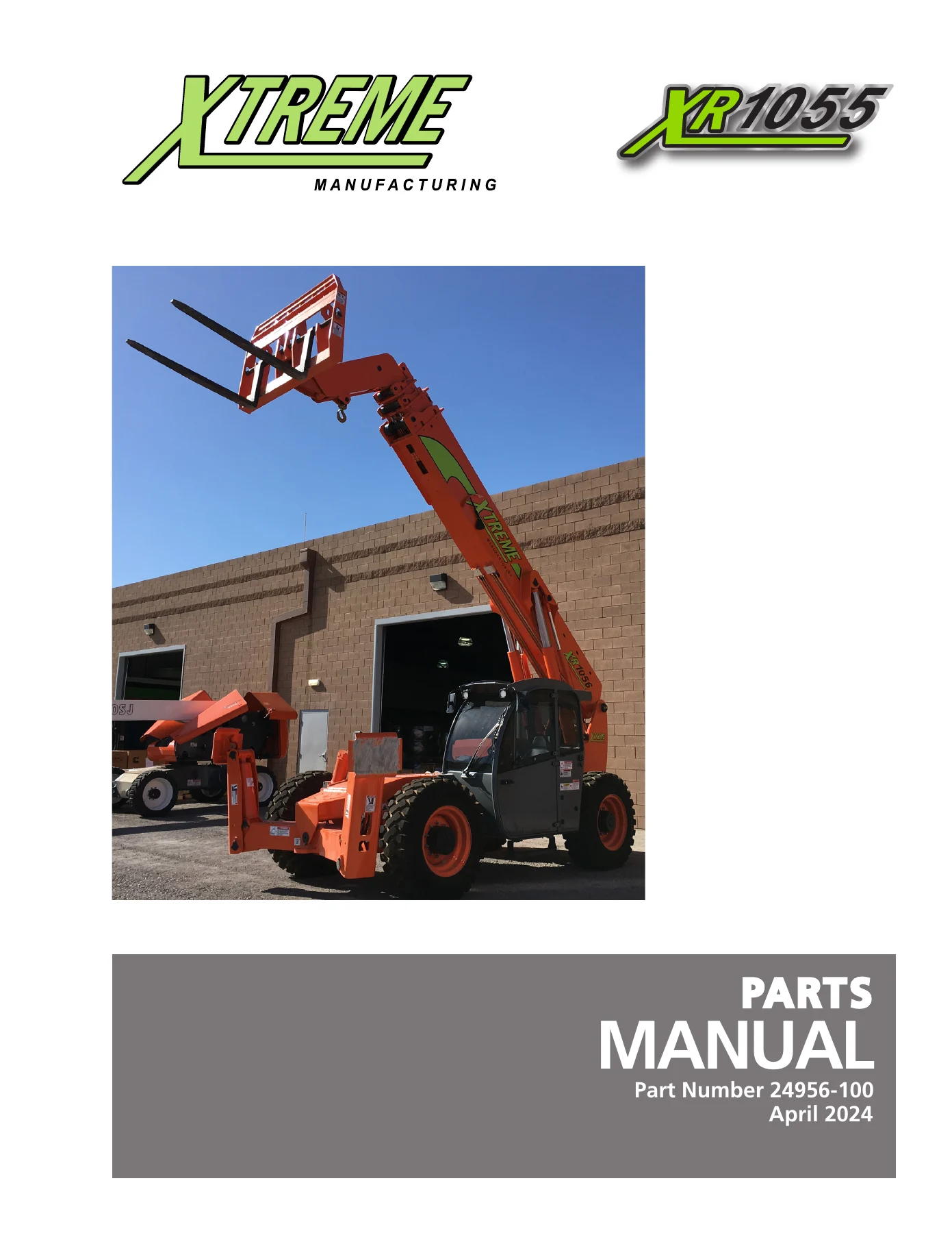
Xtreme XR1055 Telehandler Parts Manual - Complete Illustrated Parts Catalog PDF — PDF page 8 preview
Xtreme XR1055 Telehandler Parts Manual - Complete Illustrated Parts Catalog PDF — PDF page 13 preview
Xtreme XR1055 Telehandler Parts Manual - Complete Illustrated Parts Catalog PDF — PDF page 62 preview

How This Manual Helps You

This is not a generic reference that covers multiple machines in vague terms. It is the specific parts manual for the Xtreme XR1055 telehandler, with exploded diagrams that show exactly how every assembly goes together and bill-of-material tables that give you the exact part number, quantity, and description for each component. When you need to order a replacement part, you can identify it visually on the diagram, look up the callout number in the table, and have the correct Xtreme part number in hand.

The manual also accounts for production changes. Separate sections for “June 2021 and before” and “July 2021 and after” builds mean you are not guessing which version of a component fits your machine. Similarly, the boom assembly is broken down into “November 2021 and before” and “December 2021 and after” sections. This level of detail saves time and prevents ordering the wrong part.

With 686 pages of component-level coverage, this parts manual is an essential resource for anyone responsible for maintaining, repairing, or rebuilding an XR1055 telehandler. It covers the complete machine from the outriggers to the boom tip, including the engine, transmission, axles, hydraulic system, electrical system, cab, covers, and every attachment and option available for this model.

Get Your Copy Today

This Xtreme XR1055 parts manual is available as an instant PDF download. There is no shipping wait, no physical book to lose or damage, and no limitation on how many devices you can view it on. Whether you are working in the shop, in the field, or at the parts counter, you can have the complete illustrated parts catalog for the XR1055 on your phone, tablet, or computer. Print the pages you need for a specific job or keep the entire manual accessible for quick reference. When you need to identify a part, verify a component number, or put together a parts order, this manual gives you the information you need without delay.
Reviews

There are no reviews yet.

Be the first to review “Xtreme XR1055 Telehandler Parts Manual – Complete Illustrated Parts Catalog PDF”

What Our Customers Say

★★★★★ Live reviews from customers
Loading customer reviews...
0
    0
    Your Cart
    Your cart is emptyReturn to Shop
    🛒
    Recently Purchased
    🕒 verified order