
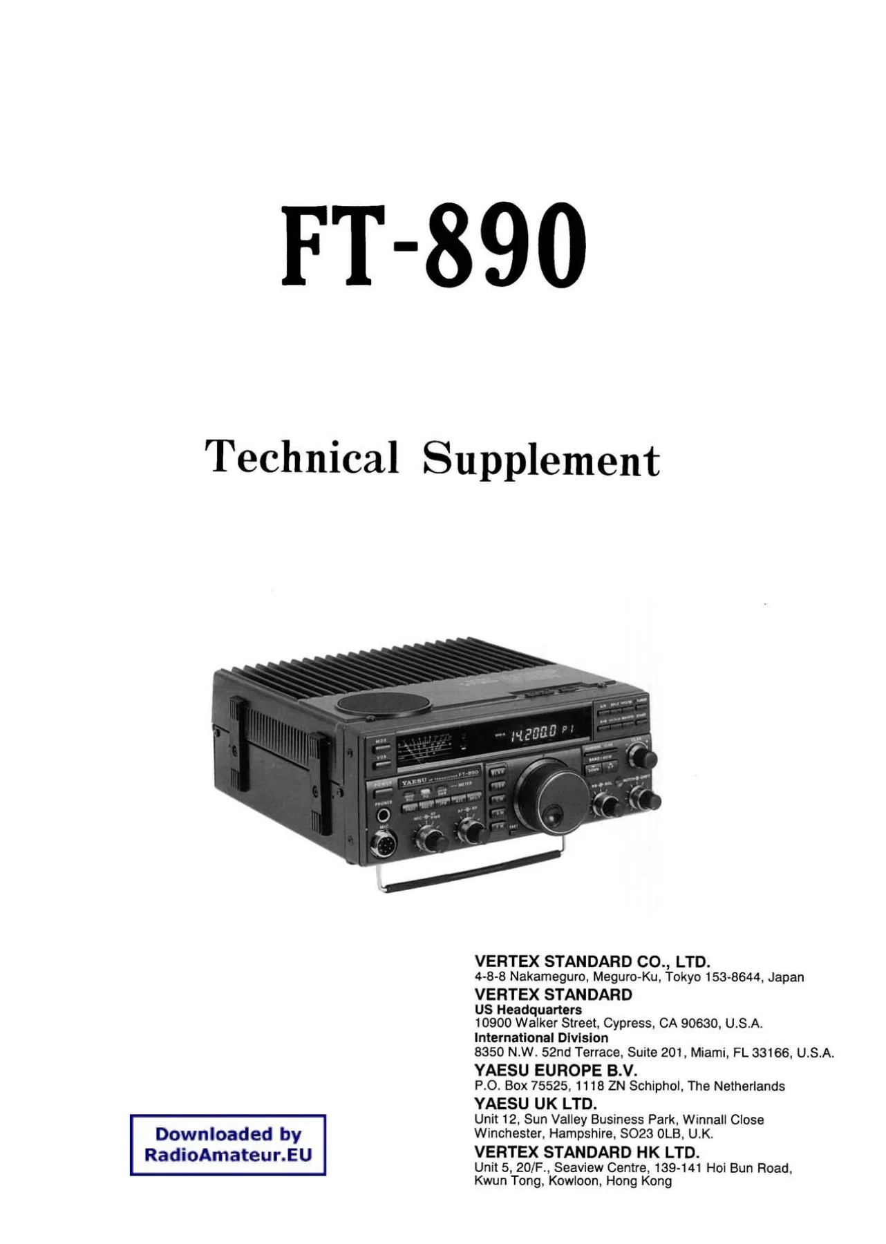
Yaesu FT-890 HF Transceiver Technical Supplement Service Manual – PDF Download
Original price was: $34.95.$19.95Current price is: $19.95.
Complete Yaesu FT-890 HF Transceiver Technical Supplement covering alignment procedures, PCB diagrams, parts lists, block and interconnection diagrams, and mechanical exploded views for every board in the transceiver.
Description
Yaesu FT-890 HF Transceiver Technical Supplement
This is the complete Yaesu FT-890 HF Transceiver Technical Supplement, the service bench companion to the FT-890 Operating Manual. It is the document Yaesu produced for qualified service technicians who need to realign, repair, or rebuild an FT-890 at board level. Across its 122 pages it delivers unit-by-unit alignment procedures, full PCB layouts with component identification, parts lists for every assembly, block and interconnection diagrams, and an exploded mechanical view of the chassis.
The Yaesu FT-890 HF Transceiver Technical Supplement is not a general operating guide. It assumes the reader already understands the transceiver’s normal operation and is ready to work inside the case with proper test equipment. That is exactly what makes it valuable: it hands you the specific test points, adjustment trimmers, and target readings that Yaesu’s own technicians used when these radios were on the bench.
File Details
- Manual type: Technical Supplement (service, alignment, and board-level repair manual)
- Brand: Yaesu (Vertex Standard)
- Model: FT-890 HF Transceiver
- Language: English
- Page count: 122
- File format: PDF
- Publication date: 1992 (Yaesu Musen Co., Ltd.)
Chapters Covered
The supplement opens with servicing prerequisites, chip component handling, and the specific warning that this equipment requires surface-mount expertise to service safely.
- Introduction & Chip Component Replacement
- Circuit Board Access, Battery & Lamp Replacement, CPU Resetting
- Alignment
- Alignment Preparation & Precautions
- Local Unit: Reference Oscillator, 70-MHz 2nd Local Oscillator, Carrier DDS Check, Sub-Loop DDS Check, Main PLL Local BPF & VCV, 1st Local Output Level Check
- PA Unit: Final Idling Current
- LPF Unit: CM Coupler Balance
- Tuner Unit: Tuning Capacitor/Motor Mechanical Check and Setting, Tuner Impedance & Phase Detection
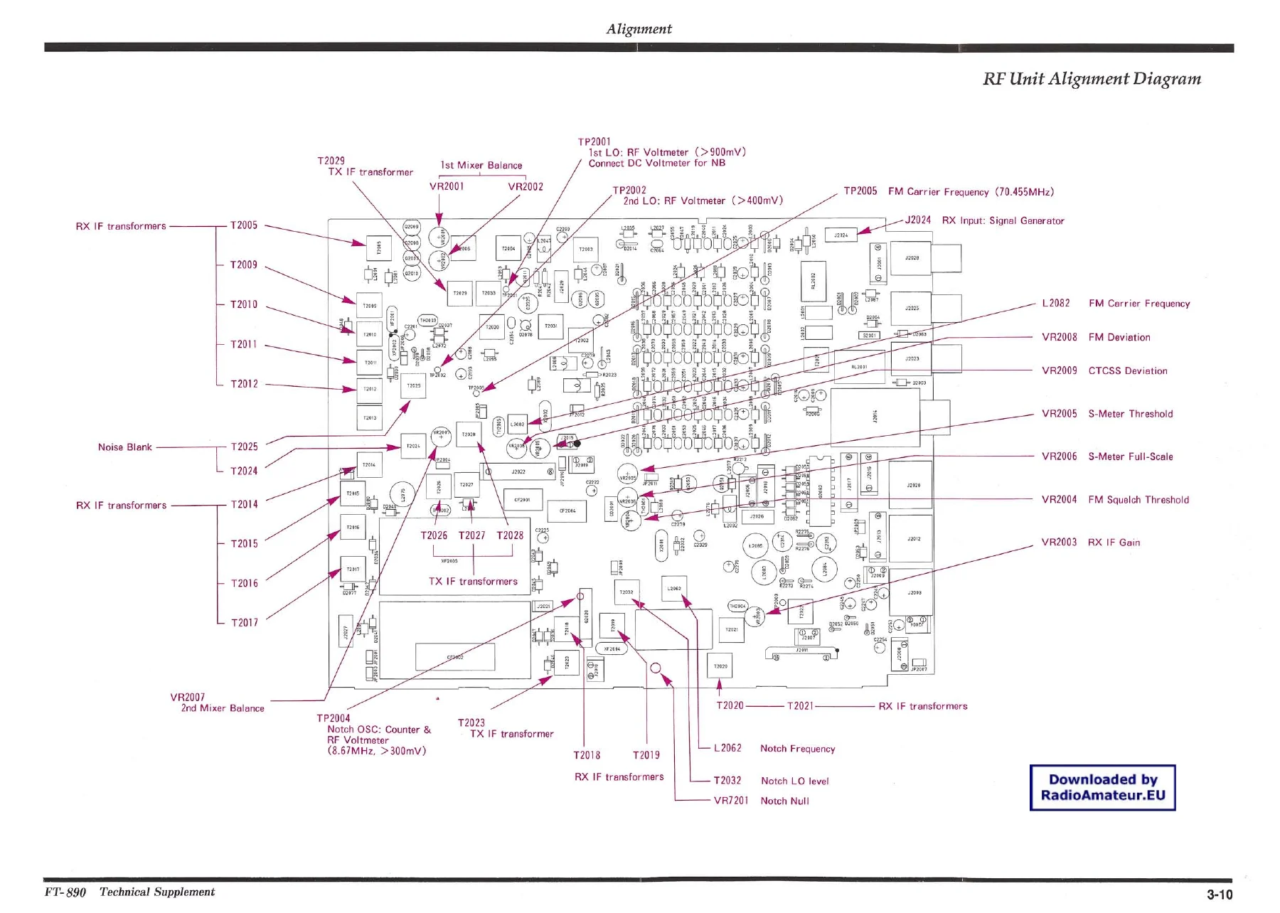
- RF Unit: Local Signals and Oscillators, Notch Oscillator
- Receiver Circuits: IF Interstage Transformers, SSB Detector Balance, 1st Mixer Balance, Meter Full Scale, S-Meter Threshold, IF Gain, S-Meter Full-Scale, Notch Null, SSB Squelch Threshold, FM Squelch Threshold
- Transmitter: ALC Meter Zero Set, Overcurrent ALC Zero Set, Transmitter IF Interstage Transformers, 2nd Tx Mixer Balance, Tx Drive, Overcurrent ALC Turndown, Forward ALC, Ext. Antenna Tuner Tuning Power, ALC Meter Sensitivity, PO Meter Calibration, Reverse ALC, SWR Meter Calibration, SSB Modulator Balance, AM Carrier Level, Speech Processor Check, FM Carrier Frequency, FM & CTCSS Deviation
- Block & Interconnection Diagrams
- PCB Diagrams & Parts Lists
- Local Unit
- RF Unit
- Display Unit
- 100-W Power Amp (PA) Unit
- LPF Unit
- Keyer Unit
- Tuner Main Unit
- Tuner Control Unit
- Carrier (CAR) DDS Unit
- PLL Sub-Loop (SUB) DDS Unit
- Notch Unit
- Potentiometer (VR) A, B & Clarifier (CLAR) Units
- Headphone (HP), Microphone (MIC) & Potentiometer (VR) C Units
- Potentiometer (VR) D & Keyer Control Units
- Switch A Unit, Switch B Unit, Switch C Unit
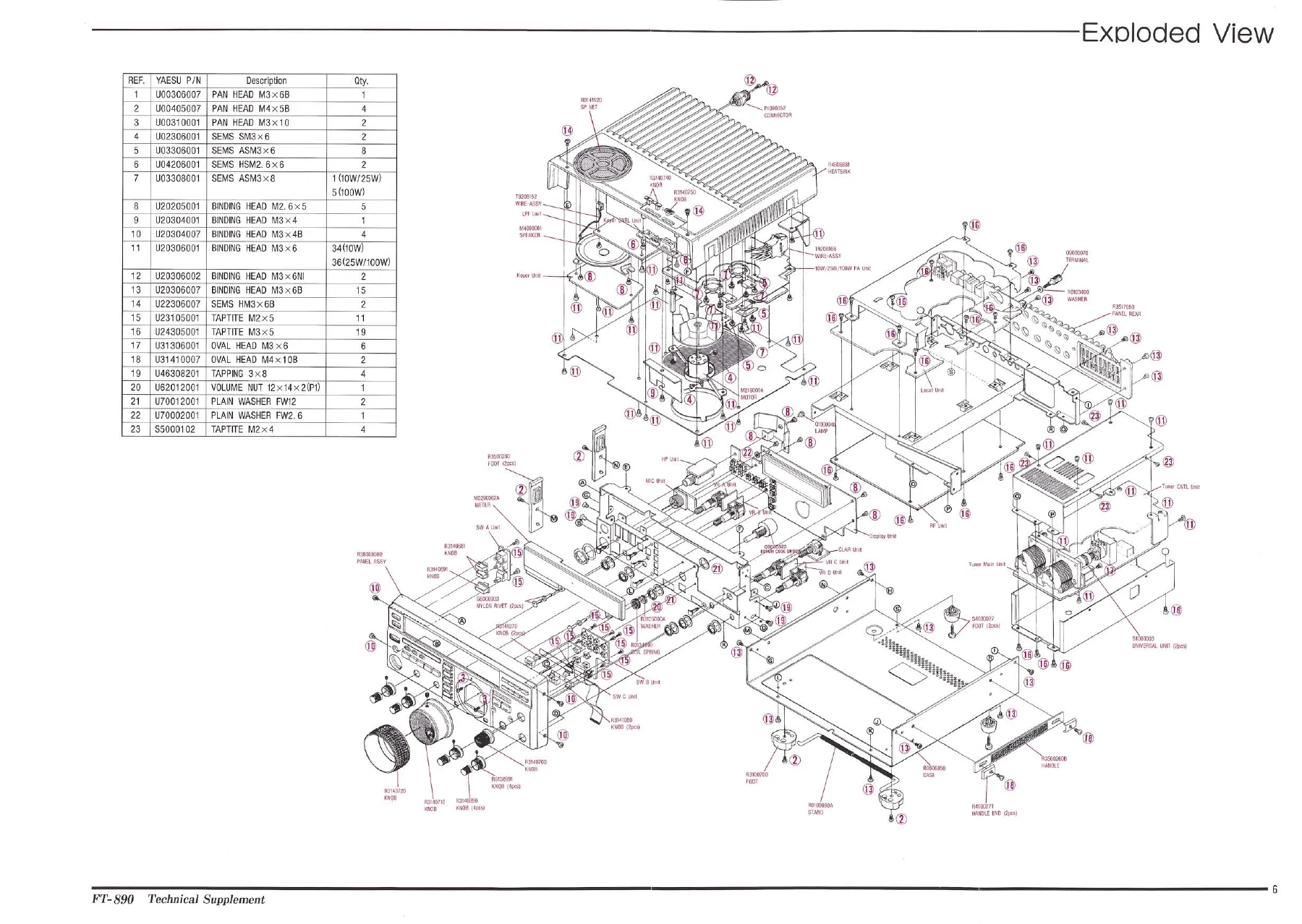
- Mechanical Details (Exploded View & Mechanical Parts)
Taken as a whole, this Yaesu FT-890 Technical Supplement gives a technician a complete, unit-by-unit path through the transceiver. Each board has its own PCB diagram, its own parts list, and its own alignment steps where adjustments exist. Test points are labeled, trimmer references match the silkscreen, and the alignment procedures name the exact target voltage, frequency, or meter deflection. Rather than guess at component locations from a general schematic, you work from the same board-level documentation Yaesu’s own service network used.
Coverage Highlights
Alignment block. The alignment section is the core of this supplement. It walks through the Local Unit reference oscillator at 10.485760 MHz, the 70-MHz second local oscillator, the Carrier DDS in LSB, USB, CW, and AM, the Sub-Loop DDS with its counter and RF millivoltmeter checks, the Main PLL Local BPF and VCV with a per-band trimmer table, and the 1st Local output level check. On the transmit side, it covers ALC meter zero, overcurrent ALC zero and turndown, forward ALC, reverse ALC (SWR turndown), SWR meter calibration, PO meter calibration, SSB modulator balance, AM carrier level, speech processor check, and FM carrier frequency plus FM/CTCSS deviation.
Test equipment list. The supplement spells out the test gear needed for complete realignment: digital DC voltmeter, DC ammeter, RF millivoltmeter, AF millivoltmeter, RF standard signal generator, AF signal generator, spectrum analyzer, oscilloscope, frequency counter, 50-ohm and 16.6-ohm dummy loads, in-line wattmeter, linear detector, and RF attenuator. It also warns that misalignment caused by improper test equipment is not covered under warranty, and it lays out the ambient temperature window and warm-up requirements for alignment.
Board access and CPU reset. The early section explains top and bottom cover removal, shield panel removal for Local Unit and PA/LPF/Keyer access, pilot lamp replacement, and the backup cell replacement procedure with the correct Sony CR2032 lithium cell. It also documents both the Soft Reset (HAM/GEN and CLAR buttons held during power-up) and the Hard Reset (Backup switch inside the bottom cover).
Parts and mechanicals. Every unit has a full reference designator parts list giving description, value, working voltage, tolerance, manufacturer’s designation, and Yaesu part number. The final section is the mechanical details, exploded view, and mechanical parts list with hardware quantities.
Who This Manual Is For
The Yaesu FT-890 HF Transceiver Technical Supplement suits the experienced amateur radio operator, the repair bench, and the collector restoring or realigning an FT-890. It is also useful to anyone replacing a failed component and needing to confirm the correct part number, verify a PCB location, or repeat a factory alignment step. Because the alignment procedures reference specific Yaesu part numbers, test points, and trimmers, this is the document that lets a shop perform the job the way it was intended rather than by trial and error.
What You Can Do With It
- Realign the Local Unit, RF Unit, PA Unit, LPF Unit, and Tuner Unit step by step
- Set ALC, PO, SWR, and S-meter calibration correctly
- Balance the SSB modulator and set AM carrier level
- Set FM carrier frequency and check FM and CTCSS deviation
- Locate every component on every board from the PCB diagrams
- Order the correct replacement part using the Yaesu part number in the parts lists
- Reset the FT-890 microprocessors with the correct soft or hard reset procedure
- Replace the backup cell and pilot lamp correctly
- Reference the block and interconnection diagrams when tracing a signal path
- Rebuild or reassemble the chassis using the exploded view and mechanical parts list
Having the right alignment targets matters on an HF transceiver. A drifting reference oscillator, a mistuned IF, or an off-balance modulator will show up as poor transmit audio, weak receive, or an inaccurate S-meter, and none of those can be fixed reliably without the factory alignment data. This supplement supplies that data.
IMAGES PREVIEW
Delivery is instant. The Yaesu FT-890 Technical Supplement downloads as a PDF immediately after payment, with no shipping and no waiting. Open it on a laptop, tablet, or phone, or print the pages you need for the bench. Whether you are chasing one specific alignment or working through an entire board-level rebuild, the FT-890 Technical Supplement gives you the documentation to do it correctly.
Reviews
There are no reviews yet.