Yale Forklift A474 (SS030BF) Service Manual – PDF DOWNLOAD
$35.95
Yale Forklift A474 (SS030BF) Service Manual – PDF DOWNLOAD
Description
Yale Forklift A474 (SS030BF) Service Manual – PDF DOWNLOAD
FILE DETAILS:
Yale Forklift A474 (SS030BF) Service Manual – PDF DOWNLOAD
Language : English
Pages : 1104
Downloadable : Yes
File Type : PDF
IMAGES PREVIEW OF THE MANUAL:
TABLE OF CONTENTS:
Yale Forklift A474 (SS030BF) Service Manual – PDF DOWNLOAD
520371764-2200YRM1230-(05-2017)-US-EN 1
General 5
Description 5
Guide Wire Physical Installation 7
Equipment 16
Specifications 18
Wire Slot and Expansion Loop Specifications 19
Material and General Specifications 20
System II Wire Guidance Specifications 22
Pre-Installation Information Form 24
520371765-2200YRM1229-(01-2012)-US-EN 29
toc 29
Wire Driver Manual 29
Safety Precautions Maintenance and Repair 30
General 33
Description 33
Installation Procedure 35
Checks and Adjustments 36
Checks 36
Adjustments 37
Troubleshooting 39
Wire Driver Troubleshooting 39
Guide Wire Troubleshooting 40
Guide Wire Repair 41
Short Circuit Repair 41
Open Circuit Repair 41
System II Wire Guidance Specifications 44
tables 29
Table 1 Wire Driver Troubleshooting 39
524150794-4000YRM0135-(03-2011)-US-EN 49
toc 49
Lift Cylinders 49
Safety Precautions Maintenance and Repair 50
Safety Procedures When Working Near Mast 53
General 57
Description 57
Lowering Control Valve 57
Cylinders (General) 60
Lift Cylinder Repair 60
Lift Cylinder Removal Without Removing Mast 60
Standard Masts With Main Lift Cylinder Fastened to Crossmember o 60
Standard and Full Free-Lift Masts With Lift Cylinder Fastened to 61
Masts That Have Two Cylinders, Main Lift Cylinder and Free-Lift 62
Disassemble 62
Assemble 62
Lift Cylinder Installation in Mast 64
Standard Masts With Main Lift Cylinder Fastened to Crossmember o 64
Standard and Full Free-Lift Masts With Lift Cylinder Fastened to 64
Chevron-Style Packing 65
Chevron-Style Packing Installation on Piston 65
Chevron-Style Packing Installation in Packing Gland 67
Lift Cylinders for HI VIS® Masts 69
Description 69
Lowering Control Valve 69
Remove 71
Disassemble 72
Assemble 72
Install 74
Main Lift Cylinders 74
Free-Lift Cylinder 74
Lift System Leak Check 74
Specifications 75
Troubleshooting 76
tables 49
Table 1 Cylinder Retainer Torque Specifications and Weight Guid 75
524150797-8000YRM0231-(02-2023)-US-EN 81
General 87
Threaded Fasteners 87
Nomenclature, Threads 87
Strength Identification 88
Cotter (Split) Pins 89
Fastener Torque Tables 94
Conversion Table 96
524150797-8000YRM0231-(03-2020)-US-EN 103
General 107
Threaded Fasteners 107
Nomenclature, Threads 107
Strength Identification 108
Cotter (Split) Pins 109
Fastener Torque Tables 114
Conversion Table 116
524153907-1900YRM0097-(05-2012)-US-EN 123
toc 123
Hydraulic Gear Pumps 123
Safety Precautions Maintenance and Repair 124
Description 127
Operation 128
Flow Control Valve 128
Relief Valve 128
Hydraulic Gear Pump Repair 129
Remove 129
Disassemble 130
Clean 130
Inspect 131
Assemble 134
Install 136
Pump Output Check 136
Method No 1 136
Method No 2 137
Hydraulic System Air Check 138
Troubleshooting 139
524158040-2240YRM0001-(01-2023)-US-EN 145
General 151
Battery Type 151
Lead-Acid Batteries 151
Lithium-Ion Batteries 152
Specific Gravity 152
Chemical Reaction in a Cell 152
Electrical Terms 154
Battery Selection 155
Battery Voltage 156
Battery as a Counterweight 156
Battery Ratings 156
Kilowatt-Hours 156
Battery Maintenance 157
Safety Procedures 157
Maintenance Records 157
New Battery 157
Cleaning Battery 158
Adding Water to Battery 160
Hydrometer 160
Battery Temperature 161
Charging Battery 162
Types of Battery Charges 163
Methods of Charging 164
Troubleshooting Charger 165
Knowing When Battery Is Fully Charged 165
Where to Charge Batteries 165
Equipment Needed 165
Battery Connectors 166
Battery Care 166
Troubleshooting 168
524158040-2240YRM0001-(03-2020)-US-EN 173
General 177
Battery Type 177
Lead-Acid Batteries 177
Lithium-Ion Batteries 178
Specific Gravity 178
Chemical Reaction in a Cell 178
Electrical Terms 180
Battery Selection 180
Battery Voltage 181
Battery as a Counterweight 182
Battery Ratings 182
Kilowatt-Hours 182
Battery Maintenance 182
Safety Procedures 182
Maintenance Records 183
New Battery 183
Cleaning Battery 183
Adding Water to Battery 185
Hydrometer 186
Battery Temperature 187
Charging Battery 188
Types of Battery Charges 188
Methods of Charging 190
Troubleshooting Charger 190
Knowing When Battery Is Fully Charged 191
Where to Charge Batteries 191
Equipment Needed 191
Battery Connectors 192
Battery Care 192
Troubleshooting 194
524163979-0100YRM0760-(01-2012)-US-EN 199
toc 199
Frame 199
Safety Precautions Maintenance and Repair 200
General 203
Description 203
Frame Repair 204
Remove and Disassemble 204
Covers, Panels, and Plates 204
Caster and Caster Wheels 204
Description 204
Caster, Replace 205
Caster Wheels, Replace 205
Painting Instructions 206
Label Replacement 206
524164052-4000YRM0763-(01-2012)-US-EN 213
toc 213
MAST 213
Safety Precautions Maintenance and Repair 214
General 217
Mast Weldments 217
Operator Platform 219
Two-Stage Mast 220
Description 220
Load Rollers 222
Operation 222
Three-Stage Mast 222
Description 222
Operation 223
524164053-4000YRM0764-(05-2018)-US-EN 227
General 231
Forks 231
Replace 231
Safety Procedures When Working Near Mast 233
Operator Platform 235
Remove 235
Install 237
Two-Stage Mast 238
Remove 238
Disassemble 238
Clean and Inspect 240
Lift Cylinders 242
Assemble 242
Install 242
Three-Stage Mast 246
Remove 246
Disassemble 246
Clean and Inspect 248
Lift Cylinders 248
Assemble 248
Install 249
Load Wheels Replacement 249
Lift System Leak Check 250
Lift Chain Adjustment 250
Mast Adjustments 251
Operator Platform Adjustment 252
Troubleshooting 253
550032941-0630YRM1460-(03-2021)-US-EN 257
GK Master Drive Unit 261
General 261
Description 261
Maintenance 262
Changing the Oil 262
Traction Motor and Drive Unit Splines 262
Remove 262
Assemble 263
Mounting Electric Motor 263
Pivoted Connection 264
Disassemble 264
Install 264
Troubleshooting 265
550032942-0620YRM1461-(01-2012)-US-EN 267
toc 267
AC Motor Repair 267
Safety Precautions Maintenance and Repair 268
General 271
Special Precautions 271
Discharging the Capacitors 271
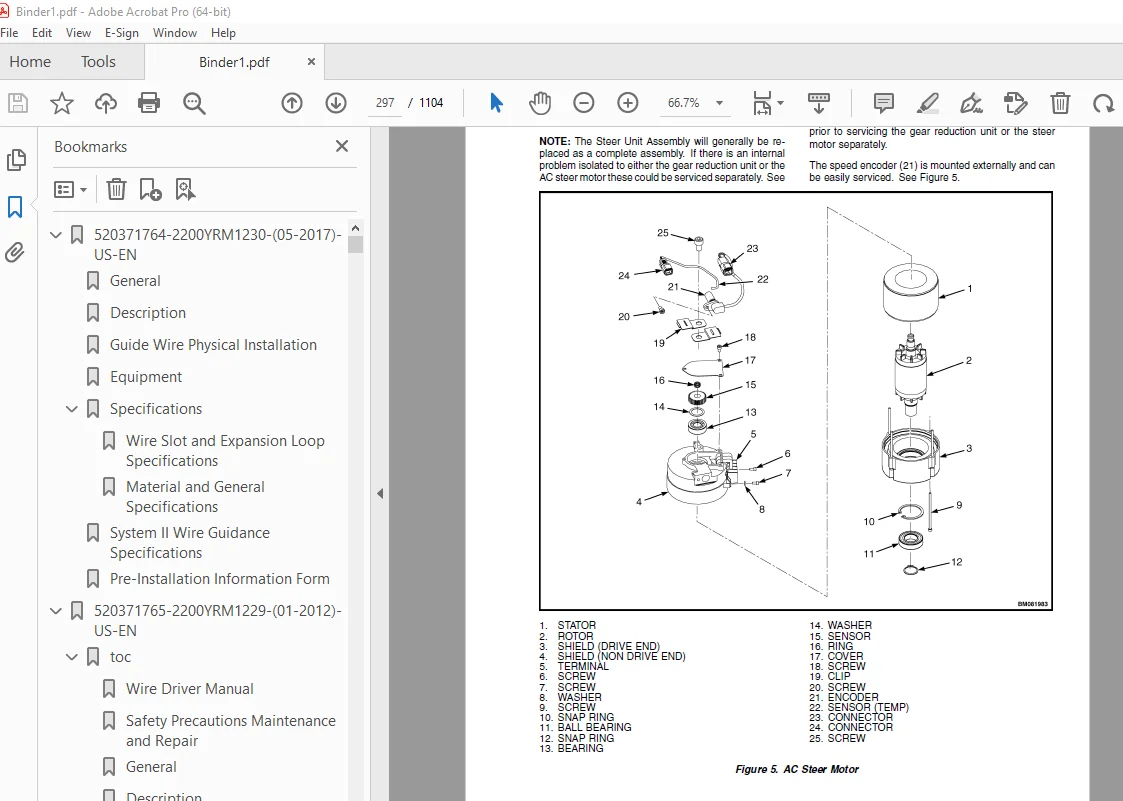
Traction Motor Repair 272
Remove 272
Disassemble 272
Inspect 273
Assemble 274
Drive End Bearing, Replace 275
Install 275
Hydraulic Motor Repair (OS/SS030BF) 276
Remove 276
Disassemble 276
Electrical Connector Repair or Replacement 278
Clean 278
Inspect 278
Assemble 279
Install 281
Troubleshooting 282
tables 267
Table 1 Speed Sensor Connector 278
Table 2 Thermal Sensor Connector 278
550032943-1600YRM1462-(01-2012)-US-EN 285
toc 285
Steering System 285
Safety Precautions Maintenance and Repair 286
General 289
Discharging The Capacitors 290
Checks, Calibrations, and Repairs 291
Electric Steering 291
Input Devices 291
Checks 291
Checks Prior to Powerup 291
Check Steering System for Correct Operation 292
Check High Lift Traction Speed Reduction and Shutoff 292
Calibrations 293
Auto-Center Steering Input Sensor Neutral 293
Drive Wheel Zero Angle Offset – Straight Travel Adjustment 294
Drive Wheel Angle (Multiturn Steering) 294
Initial Check 294
Adjustment 294
Drive Wheel Angle (Auto-Centering Steering) 294
Initial Check 294
Adjustment 295
Repairs 295
General 295
Steer Unit Assembly 295
Replace 295
Component Replacement 297
Steering Proximity Switch 298
Replace 298
Analog Input Sensor (Smart Steer) 299
Replace 299
Stepper Motor (Multiturn) 300
Replace 300
Troubleshooting 302
tables 285
Table 1 Platform Heights 292
550032944-1800YRM1463-(06-2016)-US-EN 305
General 309
Special Precautions 310
Description 311
Repair 312
Air Gap 312
Remove 313
Install 313
Operational Check 315
Troubleshooting 316
550032946-1900YRM1465-(05-2012)-US-EN 319
toc 319
Hydraulic System 319
Safety Precautions Maintenance and Repair 320
General 323
Discharging The Capacitors 323
Description 324
Hydraulic System (24/36 Volt DC Hoist) 324
Hydraulic System (36 Volt AC Hoist) 324
Control Handle 324
Control Valve 325
Description 325
Relief Valve 325
Manual Lowering Valve 325
Proportional Solenoid Valve 325
DC Hoist 325
AC Hoist 325
Solenoid Valve 325
Check and Adjust 325
Main Relief Valve 325
Lift Pump and Motor 327
Remove (DC Hoist) 327
Disassemble 328
Assemble 328
Install 328
Remove (AC Hoist) 329
Disassemble 330
Assemble 330
Install 331
Hydraulic Tank 332
Description 332
Remove and Disassemble 332
Assemble and Install 333
Troubleshooting 334
550032947-2200YRM1466-(02-2014)-US-EN 339
550032949-2200YRM1468-(01-2012)-US-EN 563
toc 563
Electrical System 563
Safety Precautions Maintenance and Repair 564
General 567
Discharging the Capacitors 568
Major Electrical System Features 569
Integrated System 569
CANbus Advantages 569
CANbus Communications 569
Electric Steering 569
Centering Proximity Sensor 569
Traction 569
CAN I/O 570
Input Devices 570
Output Devices 570
Encoder Integrity 571
Test Encoders 571
Proximity Switches 571
Key Switch 571
Multifunction Displays 571
BDI 571
Speed 571
Steer Angle 572
Truck Hours 572
Operational Mode 572
Setup 572
Setup Instructions 572
ACE0 Traction Control Unit 572
Normal Operation 572
Display 572
Password Access 572
Startup Checklist 572
Truck Operation Mode 573
Diagnostics 573
Power-On Self-Test 573
Interlocks 574
Setup Menu Diagnostics 574
Calibration 574
Traction Throttle 574
Lift/Lower Throttle 575
Proportional Valve 575
AC Traction Motor Controller 576
Controller Removal 577
Install 577
Low-Voltage Protection Function 577
AC Hoist Motor Controller 577
Controller Removal 578
Install 578
Low-Voltage Protection Function 578
Contactor and Electrical Panel Checks 578
Fuses 578
Contactors 579
General 579
Test 580
Tips 581
Disassemble and Assemble 581
Traction Throttle Sensor Removal and Installation 582
Instrument Panel Removal and Installation 584
Key Switch Removal and Installation 584
Remove 584
Install 584
Foot Switch Removal and Installation 585
Slack Chain Switch Removal and Installation 586
Limit Switch Removal and Installation 587
DC to DC Converter 587
tables 563
Table 1 Proximity Switches 571
Table 2 Coil Resistance 580
550032950-2200YRM1469-(12-2013)-US-EN 591
550032951-2200YRM1470-(12-2013)-US-EN 607
550032952-2200YRM1471-(08-2016)-US-EN 673
Introduction 677
Steering System and Wire Guidance Electric Components 678
EPS AC0 Module 678
Antenna Module 678
LED Operation 679
Alignment 679
Connection and Configuration 680
Stepper Motor (Multi-turn Steering) 681
Dual Hall Effect Sensor (Smart Steer) 681
Steering Motor Encoder 681
Centering Proximity Switch 681
Wire Guidance Parameters 682
EPS AC0 Module Parameters 682
Steer Settings 682
iSi SETTINGS PERFORMANCE Px 33 STEER RATIO
(MTS GAIN) 682
iSi SETTINGS S23
(SET STEER 0 POS) 682
Truck Settings 682
iSi SETTINGS S28 WIRE GUIDANCE
(WIRE GUIDANCE) 682
WG Config 682
iSi WG REV OFFSET S32
(WG REV OFFSET) 682
Antenna FWD and Antenna RR Module Parameters 682
WG Config 682
iSi SETTINGS S29 FWD ANT FREQ, S30 REV ANT FREQ
(LINE FREQUENCY) 682
iSi SETTINGS S34 FWD ANT LEAD, S37 REV ANT LEAD
(LEAD REGULATION) 682
iSi SETTINGS S33 FWD ANT LAG, S36 REV ANT LAG
(LAG REGULATION) 682
iSi SETTINGS S35 FWD ANT ACQ AREA, S38 REV ANT ACQ AREA
(ACQUISITION AREA) 683
iSi SETTINGS S39 WIRE DEPTH FWD, S40 WIRE DEPTH REV
(ANTENNA HEIGHT) 683
STRENGTH ACQ 683
iSi CALIBRATE C10 FREQUENCY CAL
(FREQUENCY ACQ) 683
iSi SETTINGS S31 WG SLOW SET
(WG SLOW SET) 683
Wire Guidance Setup 684
Set Frequency 684
Set Antenna Height 684
WG Antenna Calibration 684
WG Frequency Calibration 685
Set Steer 0 Position 685
Reverse Antenna Adjustment 685
Set WG REV OFFSET 686
Wire Guidance Operation 686
Wire Guidance Switch 687
Wire Acquisition 687
Steered Wheel Side 687
Load Wheel Side 688
Wire Guidance Adjustment 690
Signal Strength Setting Adjustment 690
Wire Guidance Installation 691
Forward Antenna 691
Reverse Antenna 691
OS030BF and OS030EF
692
SS030BF 694
Wire Guidance Troubleshooting 695
EPS AC0 Module Troubleshooting 695
iSi 10114, 10115 COM ERROR ANTENNA
(CODE 65516 NODE 6) 695
WG NOT CALIB 695
550032953-8000YRM1472-(03-2021)-US-EN 699
General 703
How to Move a Disabled Truck 703
How to Tow the Lift Truck 704
How to Put a Lift Truck on Blocks 704
How to Raise the Drive Tire 704
How to Raise the Load Wheels 705
Safety Procedures When Working Near Mast 706
Maintenance Schedule 708
Maintenance Procedures Every 8 Hours or Daily 719
How to Make Checks With Key Switch in the OFF Position 719
Hydraulic System 719
Battery 719
Safety Labels 720
Mast, Platform, Forks, Lift Chains, and Header Hoses 720
Inspection of Personal Fall Protection System (PFPS) 721
Pallet Clamp 721
Tire, Wheels, and Caster 721
How to Make Checks With Key Switch in the ON Position 722
Gauges, Lights, Horn, and Fuses 722
Fuses 722
Direction/Speed, Lift/Lower, and Horn Control 724
Lift System Operation 725
Parking Brake 725
Steering System 725
Maintenance Procedures Every 350 Hours or 2 Months 726
Hydraulics 726
Hydraulic Hoses 726
Hydraulic Tank Breather 726
How to Change Hydraulic Oil and Filter 726
Check for Leaks in Lift System 728
Check Lift Cylinders for Leaks 728
Electrical Inspection 729
Motor Brushes 729
Caster Wheel 730
Mast 730
Lift Chains 730
Electrical Cable Sheaves 731
Master Drive Unit 731
Maintenance Procedures Every 2000 Hours or Yearly 732
Electrical Inspection 732
Contactors 732
Master Drive Unit 732
Traction Motor and Input Pinion Splines 732
Wheels and Bearings 732
How to Change Hydraulic Oil and Filter 732
Inspection of Personal Fall Protection System (PFPS) and PFPS Tether Point 734
Battery Maintenance 735
How to Charge Battery 735
How to Change the Battery 736
General 736
Battery, Remove 736
Battery, Install 737
Wheels and Tires 739
How to Change Drive and Steer Tires 739
How to Replace Load Wheels 739
550032953-8000YRM1472-(09-2022)-US-EN 743
General 747
How to Move a Disabled Truck 747
How to Tow the Lift Truck 748
How to Put a Lift Truck on Blocks 748
How to Raise the Drive Tire 748
How to Raise the Load Wheels 749
Safety Procedures When Working Near Mast 750
Maintenance Schedule 752
Maintenance Procedures Every 8 Hours or Daily 764
How to Make Checks With Key Switch in the OFF Position 764
Hydraulic System 764
Battery 764
Safety Labels 765
Mast, Platform, Forks, Lift Chains, and Header Hoses 765
Inspection of Personal Fall Protection System (PFPS) 766
Pallet Clamp 766
Tire, Wheels, and Caster 766
How to Make Checks With Key Switch in the ON Position 767
Gauges, Lights, Horn, and Fuses 767
Fuses 767
Direction/Speed, Lift/Lower, and Horn Control 769
Lift System Operation 770
Parking Brake 770
Steering System 770
Maintenance Procedures Every 350 Hours or 2 Months 771
Hydraulics 771
Hydraulic Hoses 771
Hydraulic Tank Breather 771
How to Change Hydraulic Oil and Filter 771
Check for Leaks in Lift System 773
Check Lift Cylinders for Leaks 773
Electrical Inspection 774
Motor Brushes 774
Caster Wheel 775
Mast 775
Lift Chains 776
Electrical Cable Sheaves 777
Master Drive Unit 777
Maintenance Procedures Every 2000 Hours or Yearly 778
Electrical Inspection 778
Contactors 778
Wheels and Bearings 778
How to Change Hydraulic Oil and Filter 778
Inspection of Personal Fall Protection System (PFPS) and PFPS Tether Point 780
Battery Maintenance 781
How to Charge Battery 781
How to Change the Battery 782
General 782
Battery, Remove 782
Battery, Install 783
Wheels and Tires 785
How to Change Drive and Steer Tires 785
How to Replace Load Wheels 785
550032954-8000YRM1473-(03-2018)-US-EN 789
550032955-8000YRM1474-(10-2013)-US-EN 809
550073166-0620YRM1621-(12-2018)-US-EN 821
General 825
Special Precautions 825
Discharging the Capacitors 825
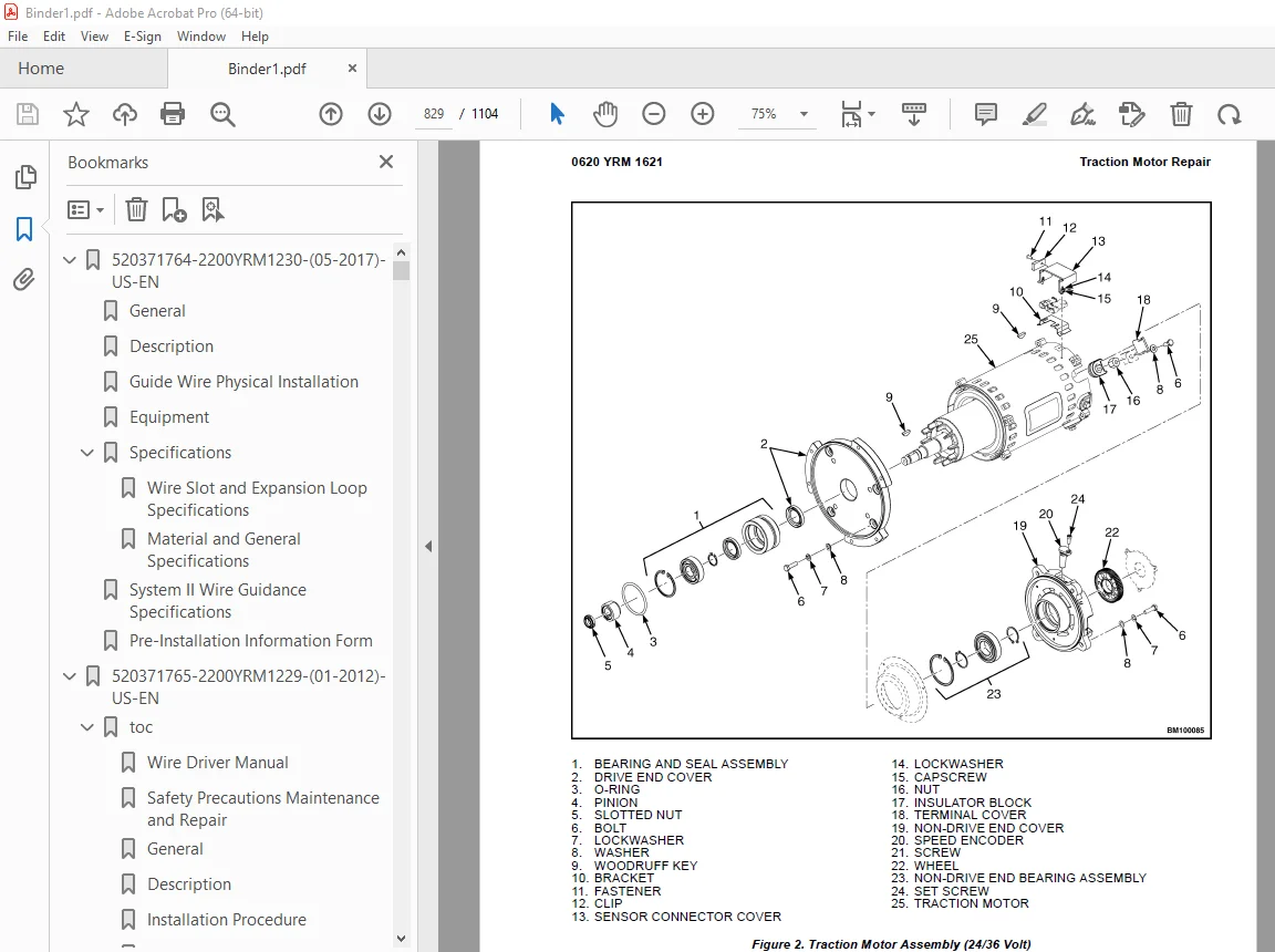
Traction Motor Repair 825
Remove 826
Disassemble 828
Clean/Inspect 832
Assemble 833
Install 834
Hydraulic Motor Repair 835
Disassemble 835
Inspect 837
Assemble 838
Special Tools 839
Tool Chart 839
Troubleshooting 840
550073167-0630YRM1609-(03-2021)-US-EN 845
Master Drive Unit 849
General 849
Description 849
Maintenance 850
Changing the Oil 850
Remove 850
Clean and Inspect 855
Install 858
Troubleshooting 859
550089217-2200YRM1650-(12-2013)-US-EN 863
550089220-2200YRM1651-(04-2020)-US-EN 879
General 887
Introduction 887
Description 887
Button Keypad 887
LED Indicator Lights 887
LCD Screen 887
Dash Display Menu Access 887
Menu Navigation 888
Dash Display Menu Operation 888
Nodes 888
Menu Structure 889
Service-Level Menu 890
Hour Meters 891
H1 Truck Hours 892
H2 Traction Hours 892
H3 Pump Hours 892
H4 Steer Hours 892
H5 Odometer Miles 892
H10 Display Hours 892
H30 Traction Node Hours 892
H40 Steer Node Hours 892
H50 Pump Node Hours 892
H70 Fwd Ant Node Hours 892
H71 Rev Ant Node Hours 892
H90 CAN I/O Hours 892
Performance 893
Performance Level 1 893
P1 1 Forward 894
P1 2 Reverse 894
P1 3 Acceleration 894
P1 4 Plug 894
P1 5 Coast 894
P1 6 Lift Speed 894
P1 7 Lower Speed 894
P1 8 Lift Accel 894
P1 9 Lift Decel 894
P1 10 Lower Accel 894
P1 11 Lower Decel 894
P1 33 Steer Ratio 895
Passwords 895
Add Password 895
Delete Password 895
Edit Password 896
Operator Password 896
Clear Log 896
Operator Logs 896
Operator 1-150 896
Information 896
I1 Series 897
I3 Serial Number 897
I5 Truck Voltage 897
Settings 897
S1 Metric 900
S2 User Performance 900
S3 Timeout 900
S4 Battery Type 900
S5 BDI Startup Full 900
S6 BDI Full 900
S7 BDI Empty 900
S8 BDI Reset 901
S9 Lift Interrupt 901
S10 Audible Warning 901
S12 Checklist 901
S13 Maint Reminder 901
S14 Restore Default 901
S15 Truck Lockout 902
S19 Lift Limit 902
S20 Lift Limit Enable 902
S21 Lower Limit 902
S22 Lower Limit Enable 902
S23 Set Steer 0 Positive 902
S25 Max CW Angle F 902
S27 Max CCW Angle F 902
S28 Wire Guidance 902
S29 Forward Antenna Freq 902
S30 Reverse Antenna Freq 902
S31 Wire Guidance Slow Set 902
S32 Wire Guidance Reverse Offset 902
S33 Forward Antenna Lag 902
S34 Forward Antenna Lead 902
S35 Forward Antenna ACQ Area 902
S36 Reverse Antenna Lag 903
S37 Reverse Antenna Lead 903
S38 Reverse Antenna ACQ Area 903
S39 Wire Depth Forward 903
S40 Wire Depth Reverse 903
S43 Simultaneity 903
S61 Extended Shift 903
S66 SWS Source 903
Software Version 904
Error Log 904
(E1) Error Log 1 905
Error 1 1 (E1 1) 905
Error 1 2 (E1 2) 905
Error 1 3 (E1 3) 905
Error 1 4 (E1 4) 905
Diagnostics 906
Diagnostics 906
D1 Status 906
D2 Input 906
D3 Output 906
D1 Status 907
D1 1 CAN 907
D1 2 Contactor 907
D1 3 Full Traction 907
D1 4 Limp Traction 907
D1 5 Steering 907
D1 6 Lift 907
D1 7 Lower 908
D2 Inputs 908
D2 10 Display 908
D2 10 1 Bus Error 909
D2 10 2 Bus Max Error 909
D2 10 30 Traction 909
D2 10 40 Steer 909
D2 10 50 Pump 909
D2 10 70 Forward Antenna 909
D2 10 71 Reverse Antenna 909
D2 10 90 CAN I/O 909
D2 30 Traction 910
D2 30 1 Target Speed 912
D2 30 2 Motor Speed 912
D2 30 3 Motor ENC 912
D2 30 5 Cont Temp 912
D2 30 6 Motor Temp 912
D2 30 7 Motor Curr 912
D2 30 8 Cap V 912
D2 30 9 Cap Max V 912
D2 30 10 Cap Min V 912
D2 30 11 Key V 912
D2 30 12 Key Max V 912
D2 30 13 Key Min V 912
D2 30 14 Brake Connect 912
D2 30 16 MC Connect 912
D2 30 19 Brake SW 912
D2 30 21 Service Key Switch 912
D2 30 22 Mast Proximity Switch 912
D2 30 26 Steer Status 913
D2 30 27 Load Hold Current 913
D2 30 28 Lift/Lower Valve Current 913
D2 30 31 Bank Out Current 913
D2 30 32 SOC 913
D2 40 Steer 913
D2 40 1 Target Speed 915
D2 40 2 Motor Speed 915
D2 40 3 Motor ENC 915
D2 40 5 Cont Temp 915
D2 40 7 Motor Curr 915
D2 40 8 Cap V 915
D2 40 9 Cap Max V 915
D2 40 10 Cap Min V 916
D2 40 11 Key V 916
D2 40 12 Key Max V 916
D2 40 13 Key Min V 916
D2 40 17 Center Prox SW 916
D2 40 18 Target Angle 916
D2 40 19 Steer Angle 916
D2 40 20 Wire Guidance Status 916
D2 40 21 APP Angle Forward 916
D2 40 22 APP Angle Reverse 916
D2 40 23 Side Error Forward 916
D2 40 24 Side Error Reverse 916
D2 40 25 Side Dist Forward 916
D2 40 26 Side Dist Reverse 916
D2 40 27 Frequency IN Range 916
D2 50 Pump 917
D2 50 1 Target Speed 918
D2 50 2 Motor Speed 918
D2 50 3 Motor ENC 918
D2 50 5 Cont Temp 918
D2 50 6 Motor Temp 918
D2 50 7 Motor Curr 918
D2 50 8 Cap V 918
D2 50 9 Cap Max V 918
D2 50 10 Cap Min V 918
D2 50 11 Key V 918
D2 50 12 Key Max V 918
D2 50 13 Key Min V 918
D2 70 Forward Antenna 919
D2 70 1 Line Frequency 919
D2 70 2 Field Strength 919
D2 70 3 Line Strength 919
D2 70 4 Path 919
D2 71 Reverse Antenna 920
D2 71 1 Line Frequency 920
D2 71 2 Field Strength 920
D2 71 3 Line Strength 920
D2 71 4 Path 920
D2 90 CAN I/O 921
D2 90 1 Height ENC 922
D2 90 2 Height ENC 922
D2 90 5 Gate Switch 923
D2 90 6 Lift Limit Switch 923
D2 90 7 Slack Chain Switch 923
D2 90 9 Brake Switch 923
D2 90 10 WG Switch 923
D2 90 14 Horn Switch 923
D2 90 15 Lift Switch 923
D2 90 16 Lower Switch 923
D2 90 17 Traction Input 923
D2 90 18 Hydraulic Input 923
D2 90 19 Auto CTR CW Sig 923
D2 90 20 Auto CTR CCW Sig 923
D2 90 21 MTS Q Line 923
D2 90 22 MTS D Line 923
D2 90 23 Steer Stat 923
D2 90 50 WG Light Connect 923
D3 Output 924
D3 10 Display 924
D3 10 10 Display Com 924
D3 10 30 Trac Comm 924
D3 10 40 Steer Com 924
D3 10 50 Pump Com 924
D3 10 70 Forward Antenna 925
D3 10 71 Reverse Antenna 925
D3 10 90 CAN I/O Com 925
D3 30 Traction 925
D3 30 1 U-V Line DC Curr 926
D3 30 2 U-W Line DC Curr 926
D3 30 3 V-W Line DC Curr 926
D3 30 4 Motor Open 926
D3 30 5 Motor Circuit 926
D3 30 6 Brake 926
D3 30 7 MC 926
D3 30 10 Lift/Lower 926
D3 30 11 Load Hold 926
D3 30 12 LH Valve Relay 926
D3 30 15 Horn 926
D3 30 17 Audible Alarm 926
D3 40 Steer 927
D3 40 1 U-V Line DC Curr 927
D3 40 2 U-W Line DC Curr 927
D3 40 3 V-W Line DC Curr 927
D3 40 4 Motor Open 927
D3 40 5 Motor Circuit 927
D3 40 6 Status Line 927
D3 50 Pump 928
D3 50 1 U-V Line DC Curr 928
D3 50 2 U-W Line DC Curr 928
D3 50 3 V-W Line DC Curr 928
D3 50 4 Motor Open 928
D3 50 5 Motor Circuit 928
D3 90 CAN I/O 929
D3 90 15 WG Light 929
D3 90 16 Sonalert 929
Calibration 929
550089223-9000YRM1648-(01-2015)-US-EN 933
550267564-0630YRM2448-(09-2022)-US-EN 1065
General 1071
General 1071
Description 1071
Discharging The Capacitors 1072
Master Drive Unit Repair 1076
Maintenance 1076
Draining the Oil 1076
Remove 1076
Disassemble 1078
Clean and Inspect 1079
Assemble 1079
Install 1080
Replace the Wheel Seal on Kordel Drive Units 1080
Tools required 1080
Truck setup 1080
Wheel shaft seal and protection ring removal (method 1) 1081
Wheel shaft seal and protection ring removal (method 2) 1081
Wheel shaft seal and protection ring installation 1083
Troubleshooting 1084
550289235-0800YRM5432-(05-2023)-US-EN 1087
Weight and Dimensions 1093
Safety and Precautions 1094
Safety Procedures For Working Near The Mast 1094
Before Starting Repairs To The Hydraulic System Always 1094
Preparing Truck For Assembly 1095
List of All Special Tools and Equipment Needed for the Assembly 1095
Preparing Mast and Platform for Initial Assembly 1095
Preparing Drive Frame for Assembly 1096
Truck Assembly 1097
Installing Mast and Platform to Drive Frame 1097
Connecting Hydraulic Hoses 1097
Connecting Electrical Connectors 1098
Installing Wire Guide Antenna 1102
Programing and Parameters 1102
Installing Drive Frame Cover 1102
General Checks After Assembly 1103
Plumbing Check 1103
Lubrication Check 1103
Functionality Check 1103
Cleaning 1103
Labels 1103
S.V 05/24