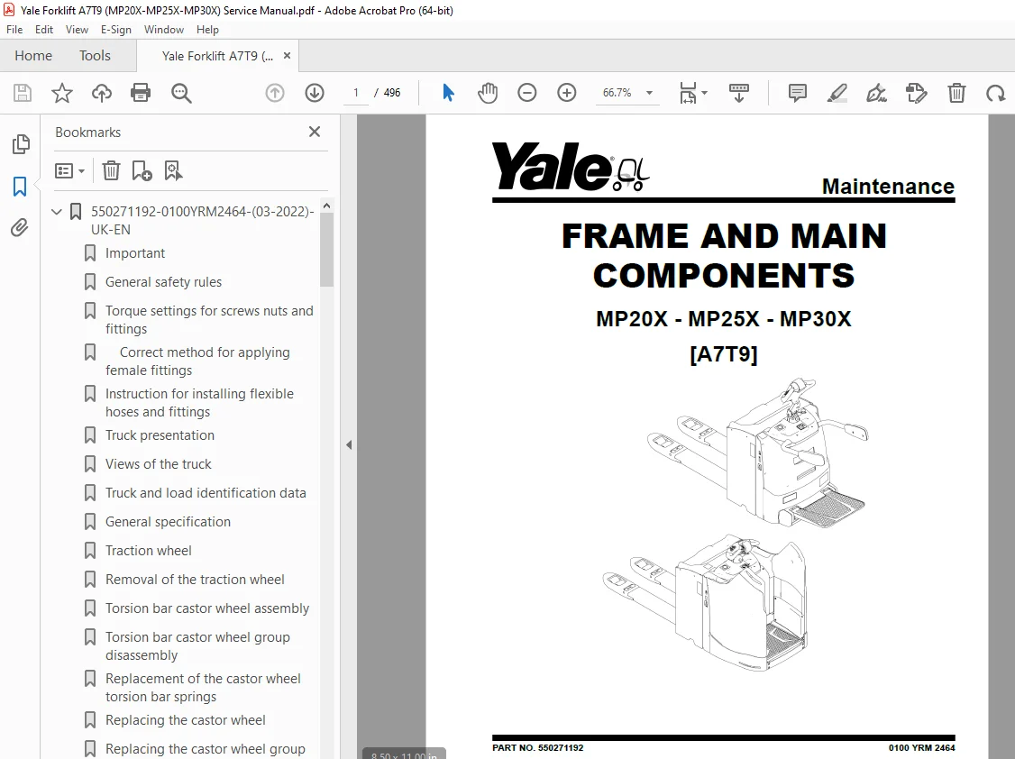
Yale Forklift A7T9 (MP20X-MP25X-MP30X) Service Manual – PDF DOWNLOAD
$29.95
Yale Forklift A7T9 (MP20X-MP25X-MP30X) Service Manual – PDF DOWNLOAD
PART NO. 550271192
Description
Yale Forklift A7T9 (MP20X-MP25X-MP30X) Service Manual – PDF DOWNLOAD
FILE DETAILS:
Yale Forklift A7T9 (MP20X-MP25X-MP30X) Service Manual – PDF DOWNLOAD
Language : English
Pages : 496
Downloadable : Yes
File Type : PDF
PART NO. 550271192
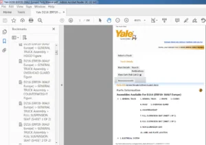
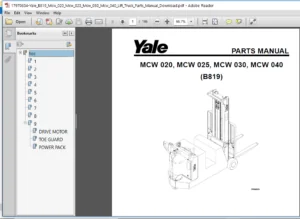
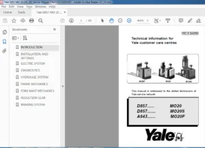
IMAGES PREVIEW OF THE MANUAL:
TABLE OF CONTENTS:
Yale Forklift A7T9 (MP20X-MP25X-MP30X) Service Manual – PDF DOWNLOAD
550271192-0100YRM2464-(03-2022)-UK-EN 1
Important 6
General safety rules 7
Torque settings for screws nuts and fittings 11
Correct method for applying female fittings 14
Instruction for installing flexible hoses and fittings 17
Truck presentation 18
Views of the truck 19
Truck and load identification data 21
General specification 24
Traction wheel 33
Removal of the traction wheel 34
Torsion bar castor wheel assembly 35
Torsion bar castor wheel group disassembly 37
Replacement of the castor wheel torsion bar springs 38
Replacing the castor wheel 39
Replacing the castor wheel group 41
Load wheels 42
Replacing the tandem load wheel 46
Replacing the tandem load wheel assembly 47
Fixed linkage 48
Adjustable linkage 49
Removal of the linkage assembly 50
Key to tiller components 52
Tiller spring replacement 56
Adjustable steering spring replacement 58
Tiller removal 59
Replacement of the potentiometer and tiller base bearings 60
Replacement of the potentiometer and tiller base bearings of the adjustable steering 62
Key to scooter components 64
Scooter head removal 66
Scooter spring replacement 67
Replacement of the scooter control sensor and base bearings 69
Side gate replacement 71
Side gates microswitch replacement 72
Removal of the platform gas spring 74
Replacement of the platform touchless sensor 75
Removal of the platform 77
Replacement of the platform sensor 79
Traction motor 81
Motor dismantling 82
Steering motor 83
Steering motor dismantling 84
Forks chassis removal 86
550271193-8000YRM2465-(03-2022)-UK-EN 91
Before Installation 96
Truck assembly 98
Topping up the oil reservoir 100
Installation of the battery with vertical extraction 101
Installation of the battery with lateral extraction 102
Connection of cables to battery 104
List and description of the settings and adjustments to be carried out 105
550271194-9000YRM2466-(03-2022)-UK-EN 107
Description of controller connectors 112
Device properties 116
Monitor menu 118
Troubleshooting 136
Warnings 137
Diagnosis system for F4-A Controller 139
Diagnosis system for Integrated Steering System 210
Electrical component measurements 269
550271195-2200YRM2467-(03-2022)-UK-EN 273
Wiring diagrams 278
Electrical components 295
Identification of the tiller head controls and of the operator panel instruments 297
Display 302
Optional keypad 305
Instructions for the use of the new keypad application 308
Truck functions 315
Steering 328
Controller F4-A 332
Controller F1 – Si 333
Installation procedure of Curtis Integrated Toolkit 335
Instructions for the use of Curtis Integrated Toolkit Software 340
Instructions to update Curtis Integrated Toolkit Software 350
Instructions to display and modify the parameters 354
Description of standard F4-A parameters 366
Description of standard ISS parameters 378
CDF file installation procedure 388
Replacement of the controllers 397
Replacement of the display 399
Replacement of the key switch 401
Replacement of the keypad (optional) 403
Replacement of the general emergency switch 405
Replacement of the horn 407
Replacement of the fuses 408
Replacement of the main contactor switch 409
Replacement of the fork lift cutout sensor 411
Replacement of the tiller sensor 413
Replacement of the tiller board 415
Replacement of tiller control springs 417
Replacement of tiller buttons 419
Replacement of the centred wheel sensor 421
Replacement of the battery charger (optional) 422
Replacement of the back-up alarm (optional) 428
Replacement of the DC/DC converter (optional) 429
Replacement of the working light (optional) 430
Replacement of the Pedestrian Awareness Light (optional) 431
550271196-1900YRM2468-(03-2022)-UK-EN 433
Hydraulic functions 438
Hydraulic diagrams 441
Hydraulic diagrams for various functions 444
Hydraulic components 450
Dismantling of cartridge soilenoid valves 453
Removal of the initial lift cylinder 457
Removal of the cylinder head bushing 459
Hydraulic power unit removal 460
Hydraulic power unit disassembly 463
550271197-0630YRM2469-(03-2022)-UK-EN 467
Identification of the master drive unit 472
Removal and disassembly of the reduction unit 473
Removal and replacement of the master drive unit assembly component 475
Braking System 478
Removal of the electromagnetic brake 480
550271198-8000YRM2470-(03-2022)-UK-EN 483
Maintenance Warnings 487
Oils and Lubricants 489
Cleaning products 490
Scheduled Maintenance 491
S.V 05/24