Yale Forklift A896 (MPE060E) Service Manual – PDF DOWNLOAD
$29.95
Yale Forklift A896 (MPE060E) Service Manual – PDF DOWNLOAD
Description
Yale Forklift A896 (MPE060E) Service Manual – PDF DOWNLOAD
FILE DETAILS:
Yale Forklift A896 (MPE060E) Service Manual – PDF DOWNLOAD
Language : English
Pages : 422
Downloadable : Yes
File Type : PDF
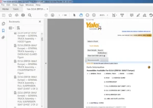
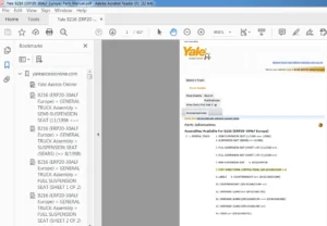
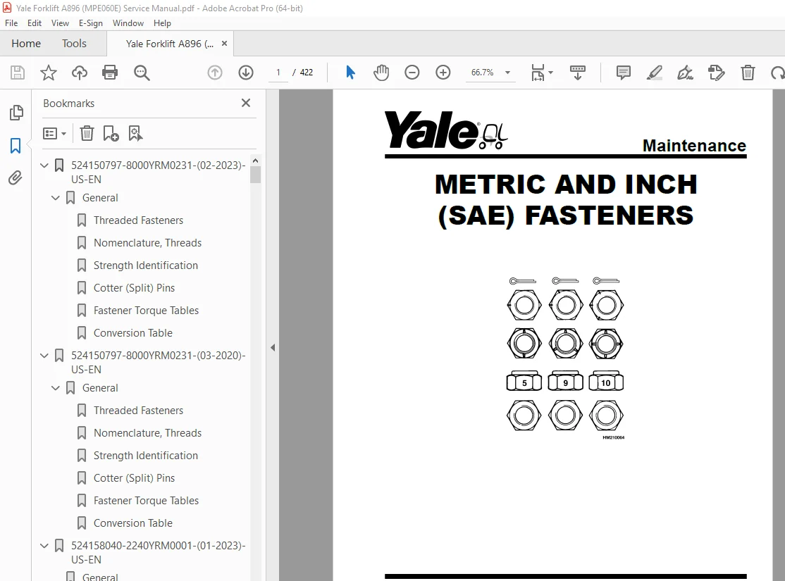
IMAGES PREVIEW OF THE MANUAL:
TABLE OF CONTENTS:
Yale Forklift A896 (MPE060E) Service Manual – PDF DOWNLOAD
524150797-8000YRM0231-(02-2023)-US-EN 1
General 7
Threaded Fasteners 7
Nomenclature, Threads 7
Strength Identification 8
Cotter (Split) Pins 9
Fastener Torque Tables 14
Conversion Table 16
524150797-8000YRM0231-(03-2020)-US-EN 23
General 27
Threaded Fasteners 27
Nomenclature, Threads 27
Strength Identification 28
Cotter (Split) Pins 29
Fastener Torque Tables 34
Conversion Table 36
524158040-2240YRM0001-(01-2023)-US-EN 43
General 49
Battery Type 49
Lead-Acid Batteries 49
Lithium-Ion Batteries 50
Specific Gravity 50
Chemical Reaction in a Cell 50
Electrical Terms 52
Battery Selection 53
Battery Voltage 54
Battery as a Counterweight 54
Battery Ratings 54
Kilowatt-Hours 54
Battery Maintenance 55
Safety Procedures 55
Maintenance Records 55
New Battery 55
Cleaning Battery 56
Adding Water to Battery 58
Hydrometer 58
Battery Temperature 59
Charging Battery 60
Types of Battery Charges 61
Methods of Charging 62
Troubleshooting Charger 63
Knowing When Battery Is Fully Charged 63
Where to Charge Batteries 63
Equipment Needed 63
Battery Connectors 64
Battery Care 64
Troubleshooting 66
524158040-2240YRM0001-(03-2020)-US-EN 71
General 75
Battery Type 75
Lead-Acid Batteries 75
Lithium-Ion Batteries 76
Specific Gravity 76
Chemical Reaction in a Cell 76
Electrical Terms 78
Battery Selection 78
Battery Voltage 79
Battery as a Counterweight 80
Battery Ratings 80
Kilowatt-Hours 80
Battery Maintenance 80
Safety Procedures 80
Maintenance Records 81
New Battery 81
Cleaning Battery 81
Adding Water to Battery 83
Hydrometer 84
Battery Temperature 85
Charging Battery 86
Types of Battery Charges 86
Methods of Charging 88
Troubleshooting Charger 88
Knowing When Battery Is Fully Charged 89
Where to Charge Batteries 89
Equipment Needed 89
Battery Connectors 90
Battery Care 90
Troubleshooting 92
524164713-0100YRM0960-(08-2016)-US-EN 97
General 101
Frame Separation and Assembly 103
Frame Separation 103
Frame Assembly 103
Painting Instructions 104
Label Replacement 104
524164715-0630YRM0961-(03-2022)-US-EN 111
General 119
Check Oil Level 120
Change Gear Oil MTR005-007-F, MPE060-080-F, MPC060-080-F, MPE060-VG, MPE080-VG, MPE060VH, and MPE080VH 121
Drive Tire 121
Remove 121
Install 121
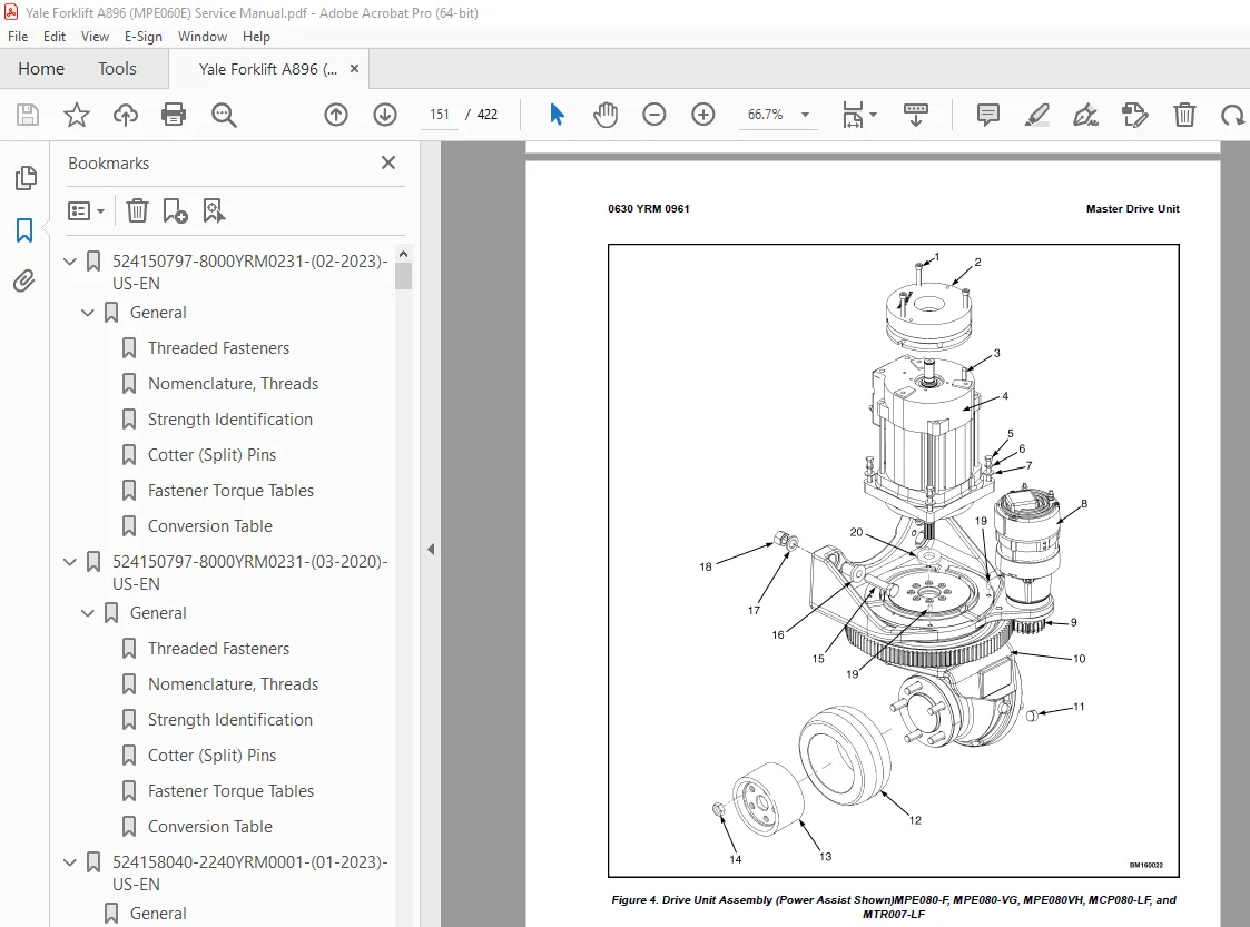
Master Drive Unit 122
Remove 122
Disassemble 129
Remove Drive Axle Group 129
Remove Upper Housing Group 130
Remove Pinion Group 130
Install 132
Troubleshooting 134
524164715-0630YRM0961-(12-2018)-US-EN 137
General 145
Check Oil Level 146
Change Gear Oil MTR005-007-F, MPE060-080-F, MPC060-080-F, MPE060-VG, MPE080-VG, MPE060VH, and MPE080VH 147
Drive Tire 147
Remove 147
Install 147
Master Drive Unit 147
Remove 147
Disassemble 154
Remove Drive Axle Group 154
Remove Upper Housing Group 154
Remove Pinion Group 154
Install 157
Troubleshooting 159
524164716-1600YRM0962-(08-2016)-US-EN 163
General 167
Special Precautions 167
Control Handle Head 168
Control Handle (MPW060/065/080-E, MSW030/040-E, MRW020/030-E, and MCW025/030/040-E) 169
Remove 169
Install 171
Control Handle (MPE060/080-E) 172
Remove (Handle) 172
Steer Bearings and Support 173
Disassemble 173
Repair 173
Assemble 173
Install (Handle) 175
Gas Spring 176
Discharging the Gas Spring 176
Remove (MPW060/065/080-E, MSW030/040-E, MRW020/030-E, and MCW025/030/040-E) 177
Remove (MPE060/080-E) 177
Install (MPW060/065/080-E, MSW030/040-E, MRW020/030-E, and MCW025/030/040-E) 177
Install (MPE060/080-E) 177
Steering and Dash Assembly (Complete)
178
Remove 178
Install 178
Troubleshooting 180
524164717-1800YRM0963-(08-2016)-US-EN 183
General 187
Description 187
Special Precautions 190
Brake Check 191
Hold On Grade Test 191
Brake Coil Check 192
Brake Assembly Repair 192
MPW060-E and MPE060-E (Up to 10/2001)
192
Remove 192
Install 193
MPW060-E and MPE060-E (10/2001 and Up), MPE080-E, MTR005-E, MTR007-E, MPC060-E, MPC080-E, MPW065-E, MPW080-E, MSW030-040-E, MRW020-030-E, and MCW025-030-040-E
195
Remove 195
Install 197
Brake Assembly Adjustment 197
Air Gap, Adjust 197
Torque Nut, Adjust 198
Adjust 199
MPW060-E, MPW080-E, and MPE060-E Equipped With Brake Assembly Part Number 524144871 199
MPW060-E, MPW080-E, MPE060-E, and All Other Models Covered by This Section Equipped With Brake Assembly Part Number 524169212 199
Troubleshooting 200
524164718-1900YRM0964-(08-2016)-US-EN 205
General 209
Description of Operation 210
Lifting a Load 211
Lowering a Load 213
Hydraulic Lines 213
Hydraulic Oil 213
Clean 213
Sound Level 213
Special Precautions 214
Hydraulic Reservoir 216
Description 216
Drive Unit Compartment Covers 216
MPC060-E, MPC080-E, MPC060-F, and MPC080-F
216
Remove 216
Install 216
MPE060-E, MPE080-E, MPE060-F, MPE080-F, MPW060-E, MPW065-E, and MPW080-E
217
Remove 217
Install 217
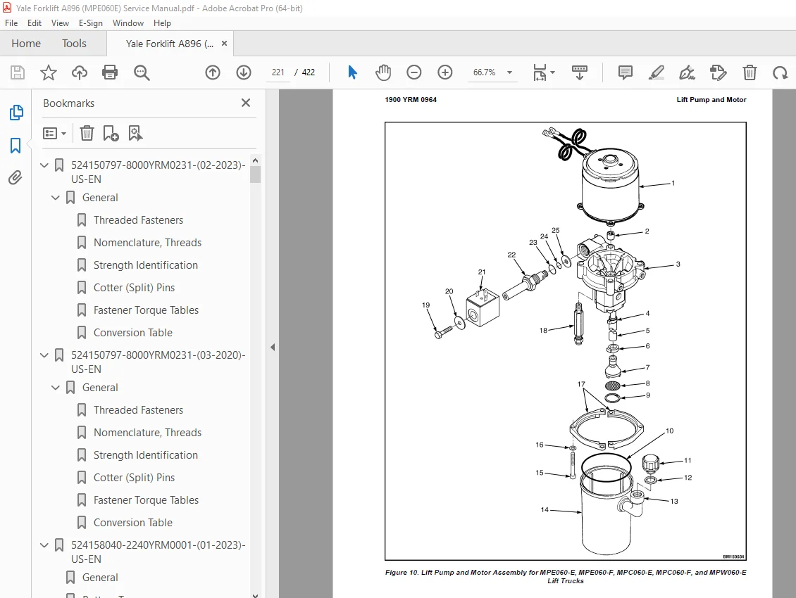
Lift Pump and Motor 218
General 218
Remove 218
Lift Pump and Motor Assembly 218
Disassemble 220
Remove Reservoir 220
Remove Pump Motor 220
MPE060-E, MPE060-F, MPC060-E, MPC060-F, and MPW060-E
220
MPE080-E, MPE080-F, MPC080-E, MPC080-F, MPW065-E, and MPW080-E
220
Disassemble Pump 220
MPE060-E, MPE060-F, MPC060-E, MPC060-F, and MPW060-E
220
MPE080-E, MPE080-F, MPC080-E, MPC080-F, MPW065-E, and MPW080-E
224
Assemble 224
Assemble Pump 224
MPE060-E, MPE060-F, MPC060-E, MPC060-F, and MPW060-E
224
MPE080-E, MPE080-F, MPC080-E, MPC080-F, MPW065-E, and MPW080-E
224
Install Pump Motor 224
Install Reservoir to Pump 225
Install 225
Lift Pump and Motor Assembly 225
Valve Repair 227
Lowering Valve 227
Remove 227
Install 227
Relief Valve 227
MPE060-E, MPE060-F, MPC060-E, MPC060-F, and MPW060-E
227
Remove 227
Install 228
MPE080-E, MPE080-F, MPC080-E, MPC080-F, MPW065-E, and MPW080-E
228
Remove 228
Install 228
Check Valve 229
MPE080-E, MPE080-F, MPC080-E, MPC080-F, MPW065-E, and MPW080-E
229
Remove 229
Install 229
Lift Cylinder 230
Remove 230
Disassemble 230
Assemble 230
Install 231
Relief Valve Adjustment 232
Relief Valve Pressure Check 232
Adjust Relief Valve Pressure 233
MPE060-E, MPE060-F, MPC060-E, MPC060-F, and MPW060-E
233
MPE080-E, MPE080-F, MPC080-E, MPC080-F, MPW065-E, and MPW080-E
234
Troubleshooting 235
Lift Assemblies 235
Lift Cylinders 236
Lift Pump and Motor Assembly 237
524164719-2200YRM0928-(09-2016)-US-EN 243
General 247
Safety Precautions 247
Description 247
Curtis PMC 1297 Transistor Motor Controller 248
Principles of Operation 248
Install 248
Programming Controller 250
1307 Programmer Handset 253
Description/Features 253
Scroll Display Keys 253
Change Value Keys 253
More Info Key 253
Operation 253
Connecting Handset to Traction Motor Controller 254
Disconnecting Handset From Traction Motor Controller 254
Programmer Self-Test 254
Menu Selections 255
Program Menu 255
Test Menu 255
Diagnostics Menu 256
Diagnostic History 256
Special Program Menu 256
Programming Traction Motor Controller – 1307 Handset 256
1311 Programmer Handset 258
Description/Features 258
Menu Navigation Key 259
Data Increase/Decrease Key 260
Bookmark Keys 260
Operation 260
Connecting Handset to Traction Motor Controller 260
Disconnecting the Handset From the Traction Motor Controller 260
Main Menu Selections 261
Program Menu 261
Monitor Menu 261
Faults Menu 262
Functions menu 263
Information Menu 263
Programmer Setup Menu 263
Programming the Traction Motor Controller – 1311 Handset 263
Parameters 265
Adjusting Parameters 265
Top Speed 265
Acceleration 265
Neutral Braking 265
Plug Braking 265
Coast Braking(MPE060-E/MPE080-E Only) 265
Empty Volts 265
Battery Discharge Indicator (BDI)/Hourmeter 266
LED Fault Codes 266
Control Card Functional Test 289
524164720-2200YRM0929-(08-2016)-US-EN 293
General 297
Electrical System Checks 300
Safety Precautions 301
Repairs 302
Controller, Replace 303
Remove 303
Install 304
Contactor Coil, Check 305
Contactor, Replace 305
Contactor Tips, Replace 305
Remove 306
Install 306
Fuses 306
Brake Switch – MPW060-E, MPW065-E, MPW080-E, MPE060-E (→Aug 2003) and MPE080-E (→Aug 2003)
307
Remove and Install 307
Brake and Interlock Switches – MPE060-E (Aug 2003→) and MPE080-E (Aug 2003→) 307
Disassemble 308
Assemble 308
Height Limit 308
Control Handle 309
Disassemble 309
Control Handle Card (Old Style) 309
Control Handle Card (New Style) 310
Configure 310
Calibrate 312
Assemble 312
Remote Control Box Switches (MPE060E and MPE080E) 314
Remove 314
Install 314
Motor Maintenance – General 314
Brush and Commutator Inspection 315
Commutator Problems 317
Brush Replacement 321
Drive Motor 323
Remove 323
Disassemble 324
Assemble 325
Install 325
Lift Pump Motor 326
Remove 326
Install 326
Commutator Repairs 326
Testing the Drive Motor 327
Damaged Field and Armature 327
Short Circuit in an Armature Winding 327
Short Circuit in the Armature 328
Open Circuit in a Field Coil 328
Short Circuit in a Field Coil 328
Short Circuit Between Field and Motor Case 329
Brush Holder 329
Troubleshooting 329
524164721-4000YRM0965-(08-2016)-US-EN 333
General 337
Description of Operation 337
Load Wheel 338
Remove 338
Install 338
Caster Wheels 339
Caster Shim Adjustment 339
Caster Replacement 341
Disassemble 342
Assemble 342
Caster Lubrication 343
Rear Link and Load Wheel Assembly 344
Remove 344
Install 345
Pull Rod 349
Remove 349
End Replacement 349
Install 350
Adjust 350
Rear Fork Adjustment 351
Rocker Arm 352
Remove 352
Install 354
Upper Link 354
Remove 354
Install 355
Troubleshooting 356
524164722-8000YRM0918-(08-2016)-US-EN 361
Hydraulic System 365
Hydraulic Oils 365
Gear Oils 365
Grease 366
Truck Weights 366
Weight (Basic Truck Without Battery) 367
Tires 367
Drive Tire 367
Torque Specifications 368
Caster Assembly 368
Master Drive Unit 368
Steering 368
Brake 368
Electrical 368
Lift Mechanism 368
Battery Specifications and Adjustments 369
MPE060E and MPW060E – 24 Volt
369
MPW065E – 12 Volt
370
MPE080E – 24 Volt
370
MPW080E – 24 Volt
371
524164723-8000YRM0919-(09-2016)-US-EN 375
General 379
How to Move a Disabled Truck 380
How to Tow the Lift Truck 380
How to Raise the Lift Truck 381
Lifting Drive/Steer Tire 381
Lifting Load Wheels 382
How to Put a Lift Truck on Blocks 382
How to Raise Drive/Steer Tire 382
How to Raise Load Wheels 383
Welding Repairs 383
Maintenance Schedule 384
Checks and Inspection Procedures 384
Hydraulic System 384
Lifting Mechanism 385
Controls 385
Electrical and Battery 386
Wheels and Tires 387
Casters 387
Lubrication Instructions 388
Every 8 Hours or Daily 389
Every 50 Hours or 1 Month 389
Every 350 Hours or 2 Months 389
Check Hydraulic Oil Level 389
Every 2000 Hours or 1 Year 389
To Fill Hydraulic Reservoir 391
Recommended Schedule of Maintenance 391
Battery Maintenance 397
How to Charge the Battery 397
Equalizing Charge 397
Normal Charge 397
Maintenance-Free Battery Charger 398
How to Change the Battery 398
524164724-8000YRM0920-(02-2018)-US-EN 403
General Notes 407
S.V 05/24