Yale Forklift A903 (MTR007-E) Service Manual – PDF DOWNLOAD
$28.95
Yale Forklift A903 (MTR007-E) Service Manual – PDF DOWNLOAD
Description
Yale Forklift A903 (MTR007-E) Service Manual – PDF DOWNLOAD
FILE DETAILS:
Yale Forklift A903 (MTR007-E) Service Manual – PDF DOWNLOAD
Language : English
Pages : 370
Downloadable : Yes
File Type : PDF
IMAGES PREVIEW OF THE MANUAL:
TABLE OF CONTENTS:
Yale Forklift A903 (MTR007-E) Service Manual – PDF DOWNLOAD
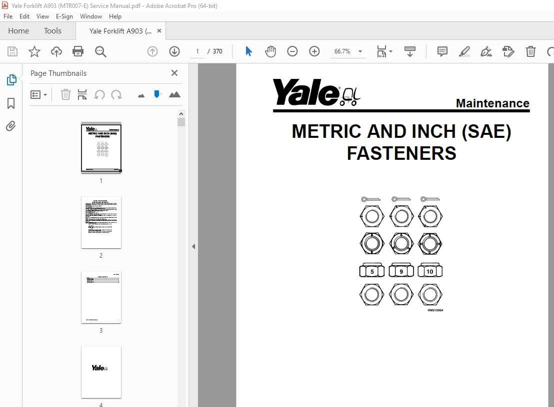
General 5
Threaded Fasteners 5
Nomenclature, Threads 5
Strength Identification 6
Cotter (Split) Pins 7
Fastener Torque Tables 12
Conversion Table 14
General 27
Battery Type 27
Lead-Acid Batteries 27
Lithium-Ion Batteries 28
Specific Gravity 28
Chemical Reaction in a Cell 28
Electrical Terms 30
Battery Selection 31
Battery Voltage 32
Battery as a Counterweight 32
Battery Ratings 32
Kilowatt-Hours 32
Battery Maintenance 33
Safety Procedures 33
Maintenance Records 33
New Battery 33
Cleaning Battery 34
Adding Water to Battery 36
Hydrometer 36
Battery Temperature 37
Charging Battery 38
Types of Battery Charges 39
Methods of Charging 40
Troubleshooting Charger 41
Knowing When Battery Is Fully Charged 41
Where to Charge Batteries 41
Equipment Needed 41
Battery Connectors 42
Battery Care 42
Troubleshooting 44
General 53
Battery Type 53
Lead-Acid Batteries 53
Lithium-Ion Batteries 54
Specific Gravity 54
Chemical Reaction in a Cell 54
Electrical Terms 56
Battery Selection 56
Battery Voltage 57
Battery as a Counterweight 58
Battery Ratings 58
Kilowatt-Hours 58
Battery Maintenance 58
Safety Procedures 58
Maintenance Records 59
New Battery 59
Cleaning Battery 59
Adding Water to Battery 61
Hydrometer 62
Battery Temperature 63
Charging Battery 64
Types of Battery Charges 64
Methods of Charging 66
Troubleshooting Charger 66
Knowing When Battery Is Fully Charged 67
Where to Charge Batteries 67
Equipment Needed 67
Battery Connectors 68
Battery Care 68
Troubleshooting 70
General 83
Check Oil Level 84
Change Gear Oil MTR005-007-F, MPE060-080-F, MPC060-080-F, MPE060-VG, MPE080-VG, MPE060VH, and MPE080VH 85
Drive Tire 85
Remove 85
Install 85
Master Drive Unit 86
Remove 86
Disassemble 93
Remove Drive Axle Group 93
Remove Upper Housing Group 94
Remove Pinion Group 94
Install 96
Troubleshooting 98
General 109
Check Oil Level 110
Change Gear Oil MTR005-007-F, MPE060-080-F, MPC060-080-F, MPE060-VG, MPE080-VG, MPE060VH, and MPE080VH 111
Drive Tire 111
Remove 111
Install 111
Master Drive Unit 111
Remove 111
Disassemble 118
Remove Drive Axle Group 118
Remove Upper Housing Group 118
Remove Pinion Group 118
Install 121
Troubleshooting 123
General 131
Description 131
Special Precautions 134
Brake Check 135
Hold On Grade Test 135
Brake Coil Check 136
Brake Assembly Repair 136
MPW060-E and MPE060-E (Up to 10/2001)
136
Remove 136
Install 137
MPW060-E and MPE060-E (10/2001 and Up), MPE080-E, MTR005-E, MTR007-E, MPC060-E, MPC080-E, MPW065-E, MPW080-E, MSW030-040-E, MRW020-030-E, and MCW025-030-040-E
139
Remove 139
Install 141
Brake Assembly Adjustment 141
Air Gap, Adjust 141
Torque Nut, Adjust 142
Adjust 143
MPW060-E, MPW080-E, and MPE060-E Equipped With Brake Assembly Part Number 524144871 143
MPW060-E, MPW080-E, MPE060-E, and All Other Models Covered by This Section Equipped With Brake Assembly Part Number 524169212 143
Troubleshooting 144
General 153
Safety Precautions 153
Description 153
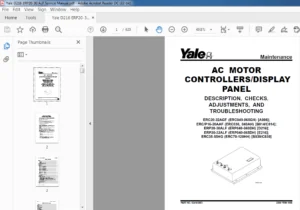
Curtis PMC 1297 Transistor Motor Controller 154
Principles of Operation 154
Install 154
Programming Controller 156
1307 Programmer Handset 159
Description/Features 159
Scroll Display Keys 159
Change Value Keys 159
More Info Key 159
Operation 159
Connecting Handset to Traction Motor Controller 160
Disconnecting Handset From Traction Motor Controller 160
Programmer Self-Test 160
Menu Selections 161
Program Menu 161
Test Menu 161
Diagnostics Menu 162
Diagnostic History 162
Special Program Menu 162
Programming Traction Motor Controller – 1307 Handset 162
1311 Programmer Handset 164
Description/Features 164
Menu Navigation Key 165
Data Increase/Decrease Key 166
Bookmark Keys 166
Operation 166
Connecting Handset to Traction Motor Controller 166
Disconnecting the Handset From the Traction Motor Controller 166
Main Menu Selections 167
Program Menu 167
Monitor Menu 167
Faults Menu 168
Functions menu 169
Information Menu 169
Programmer Setup Menu 169
Programming the Traction Motor Controller – 1311 Handset 169
Parameters 171
Adjusting Parameters 171
Top Speed 171
Acceleration 171
Neutral Braking 171
Plug Braking 171
Coast Braking(MPE060-E/MPE080-E Only) 171
Empty Volts 171
Battery Discharge Indicator (BDI)/Hourmeter 172
LED Fault Codes 172
Control Card Functional Test 195
toc 199
Frame 199
Safety Precautions Maintenance and Repair 200
General 203
Description 203
Features 205
MPC060-E, MPC060-F, MPC080-E, and MPC080-F 205
MTR005-E, MTR005-F, MTR007-E, and MTR007-F 206
Covers 206
Special Precautions 208
Frame Separation and Assembly 210
MPC060-E, MPC060-F, MPC080-E, and MPC080-F 210
Frame Separation 210
Painting Instructions 210
Label Replacement 211
Battery Compartment 211
tables 199
Table 1 Wheel Base and Fork Length 205
Table 2 Wheel Base and Fork Length 205
Table 3 Wheel Base and Fork Length 205
Table 4 Wheel Base and Fork Length 206
toc 219
Steering Mechanism 219
Safety Precautions Maintenance and Repair 220
Introduction 223
General 223
Description of Operation 223
Special Precautions 223
Control Handle 225
Remove 225
Install 225
Support Assembly 227
Remove 227
Disassemble 227
Repair 227
Assemble 228
Install 228
Control Handle and Support Assembly (Complete) 228
Remove 228
Install 229
Troubleshooting 231
toc 235
Periodic Maintenance 235
Safety Precautions Maintenance and Repair 236
Introduction 239
General 239
Drive Unit Compartment Covers 239
Remove 239
Install 239
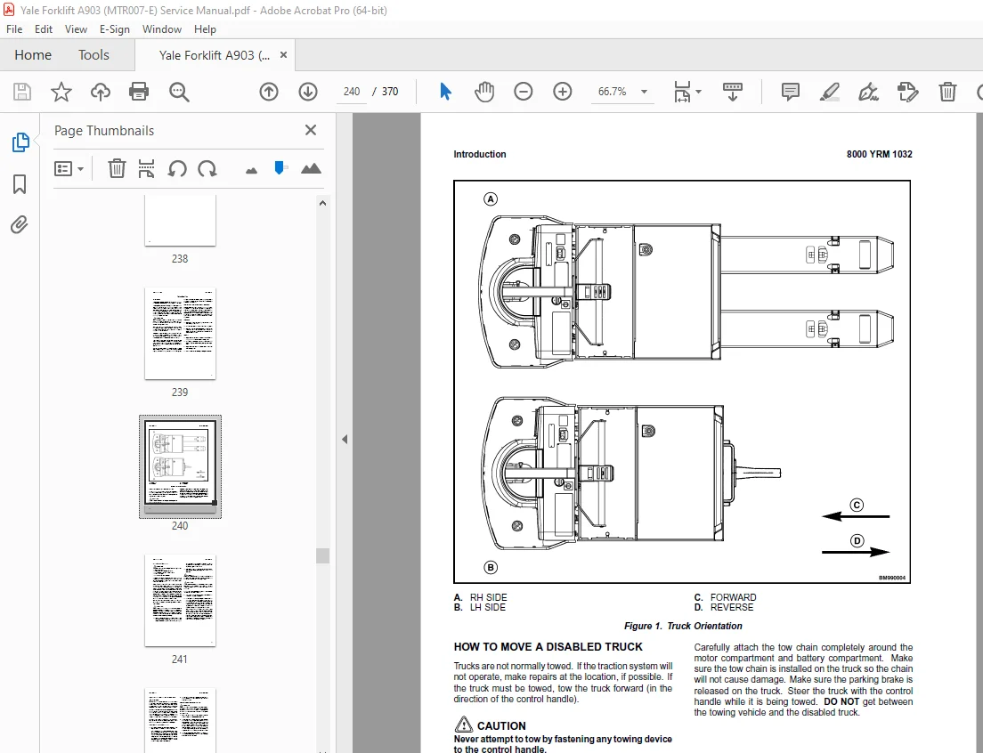
How to Move a Disabled Truck 240
How to Tow the Truck 241
How to Put the Truck on Blocks 242
How to Raise Drive/Steer Tire 242
How to Raise the Load Wheels 242
Special Precautions 243
Maintenance Schedule 244
Maintenance Procedures Every 8 Hours or Daily 247
Checks With the Key Switch OFF 247
Safety Labels 247
Battery 248
Frame 248
Load Wheels, Drive Tire, and Casters 248
Lift Linkage ( MPC060-E and MPC080-E ) 249
Coupler ( MTR005-E and MTR007-E ) 249
Steering Operation 249
Checks With the Key Switch ON 249
Control Handle 249
Gauges 249
Fuses 250
High Speed Switch 250
Hydraulic (MPC060-E and MPC080-E) 250
Hand Brake 250
Maintenance Procedures Every 350 Hours or Every 2 Months 251
Battery Equalizing Charge 251
Coupler Lubrication (MTR005-E and MTR007-E) 251
Control Handle Pivot 251
Brakes 251
Drive Tire and Wheel 252
Drive Unit Assembly 252
Check Oil Level 252
Motor Brushes 252
Maintenance Procedures Every 2000 Hours or Yearly 253
Load Wheel Bearings (MTR005-E and MTR007-E) 253
Remove 253
Inspect 254
Install 254
Contactor 254
Inspecting the Contacts 255
Hydraulic System (MPC060-E and MPC080-E) 256
Changing the Hydraulic Oil 256
Master Drive Unit 261
Drive Unit Gear Oil 261
Welding Repairs 262
Battery Maintenance 262
How to Charge Battery 262
How to Change Battery 263
Adjusting the Battery Spacers 264
Changing Battery With Rollers 264
Remove 264
Install 264
Remove Battery Using Overhead Crane 264
Install Battery Using Overhead Crane 265
Battery Specifications 266
tables 235
Table 1 Maintenance Schedule 244
Table 2 Specific Gravity Corrections 263
Table 3 Battery Specifications (MTR005-E) 266
Table 4 Battery Specifications (MTR007-E) 266
Table 5 Battery Specifications (MPC060-E) 267
Table 6 Battery Specifications (MPC080-E) 267
toc 271
Capacities and Specifications 271
Safety Precautions Maintenance and Repair 272
Hydraulic System (MPC060/080-E and MPC060/080-F) 275
Hydraulic Oils 275
Master Drive Unit Specifications 276
Gear Oils 276
Grease 277
Tire Specifications 277
Torque Specifications 278
Master Drive Unit 278
Brake 278
Steering 278
Electrical 278
Coupler ( MTR005-E, MTR005-E AC, MTR007-E, and MTR007-E ) 278
Lift Pump ( MPC060-E, MPC060-E AC, MPC080-E, and MPC080-E AC ) 278
Travel Speeds 279
MTR005-E, MTR005-E AC, MTR007-E, and MTR007-E 279
MPC060-E, MPC060-E AC, MPC080-E, and MPC080-E AC 279
Truck Weight 279
Battery Specifications and Adjustments 280
toc 283
Diagrams 283
Safety Precautions Maintenance and Repair 284
toc 315
Electrical System 315
Safety Precautions Maintenance and Repair 316
Introduction 319
General 319
Description of Operation 319
Special Precautions 324
Electrical System Checks 325
Repairs 325
Controller, Replace 326
Remove 326
Install 326
Control Handle Module 326
Check 326
Remove 328
Install 328
Contactor, Replace 329
Remove 329
Install 329
Contactor Coil, Check 329
Contactor Tips, Replace 330
Remove 330
Install 330
Key Switch 331
Remove 331
Install 331
Parking Brake Switch 331
Remove 331
Install 331
Battery Indicator/Hourmeter Display 332
Remove 332
Install 332
Fuses 332
High Speed Switch Assembly 333
Remove 333
Install 333
Control Handle 334
Disassemble 334
Hand-brake 334
Upper Cover 334
Handle Shaft 335
Lower Cover 335
Directional/Throttle Switch 335
Neutral Switches 335
Throttle Sensor 335
Assemble 339
Directional/Throttle Switch 339
Neutral Switches 339
Throttle Sensor 340
Lower Cover 340
Handle Shaft 340
Upper Cover 341
Hand-brake 341
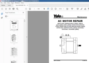
Drive Motor 342
Remove 342
Disassemble 342
Assemble 342
Install 345
Lift Pump Motor (MPC060-E and MPC080-E Only) 345
Remove 345
Install 345
Troubleshooting 346
General Troubleshooting 346
tables 315
Table 1 Input Connector (J4) Voltages 329
General 355
Threaded Fasteners 355
Nomenclature, Threads 355
Strength Identification 356
Cotter (Split) Pins 357
Fastener Torque Tables 362
Conversion Table 364
S.V 06/24