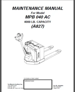
Yale Forklift A904 (MPC060-E) Service Manual – PDF DOWNLOAD
$28.95
Yale Forklift A904 (MPC060-E) Service Manual – PDF DOWNLOAD
Description
Yale Forklift A904 (MPC060-E) Service Manual – PDF DOWNLOAD
FILE DETAILS:
Yale Forklift A904 (MPC060-E) Service Manual – PDF DOWNLOAD
Language : English
Pages : 382
Downloadable : Yes
File Type : PDF
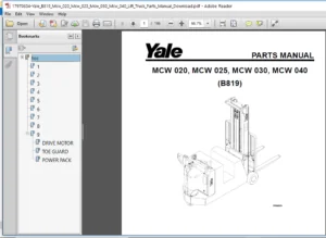
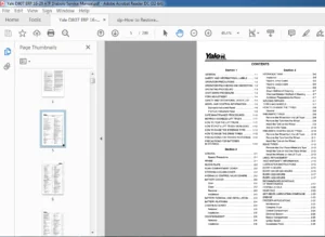
IMAGES PREVIEW OF THE MANUAL:
TABLE OF CONTENTS:
Yale Forklift A904 (MPC060-E) Service Manual – PDF DOWNLOAD
General 5
Threaded Fasteners 5
Nomenclature, Threads 5
Strength Identification 6
Cotter (Split) Pins 7
Fastener Torque Tables 12
Conversion Table 14
General 29
Check Oil Level 30
Change Gear Oil MTR005-007-F, MPE060-080-F, MPC060-080-F, MPE060-VG, MPE080-VG, MPE060VH, and MPE080VH 31
Drive Tire 31
Remove 31
Install 31
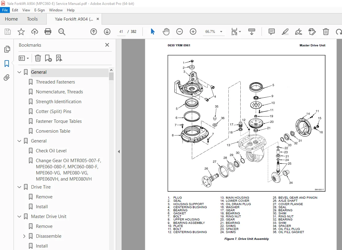
Master Drive Unit 32
Remove 32
Disassemble 39
Remove Drive Axle Group 39
Remove Upper Housing Group 40
Remove Pinion Group 40
Install 42
Troubleshooting 44
General 55
Check Oil Level 56
Change Gear Oil MTR005-007-F, MPE060-080-F, MPC060-080-F, MPE060-VG, MPE080-VG, MPE060VH, and MPE080VH 57
Drive Tire 57
Remove 57
Install 57
Master Drive Unit 57
Remove 57
Disassemble 64
Remove Drive Axle Group 64
Remove Upper Housing Group 64
Remove Pinion Group 64
Install 67
Troubleshooting 69
General 77
Description 77
Special Precautions 80
Brake Check 81
Hold On Grade Test 81
Brake Coil Check 82
Brake Assembly Repair 82
MPW060-E and MPE060-E (Up to 10/2001)
82
Remove 82
Install 83
MPW060-E and MPE060-E (10/2001 and Up), MPE080-E, MTR005-E, MTR007-E, MPC060-E, MPC080-E, MPW065-E, MPW080-E, MSW030-040-E, MRW020-030-E, and MCW025-030-040-E
85
Remove 85
Install 87
Brake Assembly Adjustment 87
Air Gap, Adjust 87
Torque Nut, Adjust 88
Adjust 89
MPW060-E, MPW080-E, and MPE060-E Equipped With Brake Assembly Part Number 524144871 89
MPW060-E, MPW080-E, MPE060-E, and All Other Models Covered by This Section Equipped With Brake Assembly Part Number 524169212 89
Troubleshooting 90
General 99
Description of Operation 100
Lifting a Load 101
Lowering a Load 103
Hydraulic Lines 103
Hydraulic Oil 103
Clean 103
Sound Level 103
Special Precautions 104
Hydraulic Reservoir 106
Description 106
Drive Unit Compartment Covers 106
MPC060-E, MPC080-E, MPC060-F, and MPC080-F
106
Remove 106
Install 106
MPE060-E, MPE080-E, MPE060-F, MPE080-F, MPW060-E, MPW065-E, and MPW080-E
107
Remove 107
Install 107
Lift Pump and Motor 108
General 108
Remove 108
Lift Pump and Motor Assembly 108
Disassemble 110
Remove Reservoir 110
Remove Pump Motor 110
MPE060-E, MPE060-F, MPC060-E, MPC060-F, and MPW060-E
110
MPE080-E, MPE080-F, MPC080-E, MPC080-F, MPW065-E, and MPW080-E
110
Disassemble Pump 110
MPE060-E, MPE060-F, MPC060-E, MPC060-F, and MPW060-E
110
MPE080-E, MPE080-F, MPC080-E, MPC080-F, MPW065-E, and MPW080-E
114
Assemble 114
Assemble Pump 114
MPE060-E, MPE060-F, MPC060-E, MPC060-F, and MPW060-E
114
MPE080-E, MPE080-F, MPC080-E, MPC080-F, MPW065-E, and MPW080-E
114
Install Pump Motor 114
Install Reservoir to Pump 115
Install 115
Lift Pump and Motor Assembly 115
Valve Repair 117
Lowering Valve 117
Remove 117
Install 117
Relief Valve 117
MPE060-E, MPE060-F, MPC060-E, MPC060-F, and MPW060-E
117
Remove 117
Install 118
MPE080-E, MPE080-F, MPC080-E, MPC080-F, MPW065-E, and MPW080-E
118
Remove 118
Install 118
Check Valve 119
MPE080-E, MPE080-F, MPC080-E, MPC080-F, MPW065-E, and MPW080-E
119
Remove 119
Install 119
Lift Cylinder 120
Remove 120
Disassemble 120
Assemble 120
Install 121
Relief Valve Adjustment 122
Relief Valve Pressure Check 122
Adjust Relief Valve Pressure 123
MPE060-E, MPE060-F, MPC060-E, MPC060-F, and MPW060-E
123
MPE080-E, MPE080-F, MPC080-E, MPC080-F, MPW065-E, and MPW080-E
124
Troubleshooting 125
Lift Assemblies 125
Lift Cylinders 126
Lift Pump and Motor Assembly 127
General 137
Safety Precautions 137
Description 137
Curtis PMC 1297 Transistor Motor Controller 138
Principles of Operation 138
Install 138
Programming Controller 140
1307 Programmer Handset 143
Description/Features 143
Scroll Display Keys 143
Change Value Keys 143
More Info Key 143
Operation 143
Connecting Handset to Traction Motor Controller 144
Disconnecting Handset From Traction Motor Controller 144
Programmer Self-Test 144
Menu Selections 145
Program Menu 145
Test Menu 145
Diagnostics Menu 146
Diagnostic History 146
Special Program Menu 146
Programming Traction Motor Controller – 1307 Handset 146
1311 Programmer Handset 148
Description/Features 148
Menu Navigation Key 149
Data Increase/Decrease Key 150
Bookmark Keys 150
Operation 150
Connecting Handset to Traction Motor Controller 150
Disconnecting the Handset From the Traction Motor Controller 150
Main Menu Selections 151
Program Menu 151
Monitor Menu 151
Faults Menu 152
Functions menu 153
Information Menu 153
Programmer Setup Menu 153
Programming the Traction Motor Controller – 1311 Handset 153
Parameters 155
Adjusting Parameters 155
Top Speed 155
Acceleration 155
Neutral Braking 155
Plug Braking 155
Coast Braking(MPE060-E/MPE080-E Only) 155
Empty Volts 155
Battery Discharge Indicator (BDI)/Hourmeter 156
LED Fault Codes 156
Control Card Functional Test 179
General 187
Description of Operation 187
Load Wheel 188
Remove 188
Install 188
Caster Wheels 189
Caster Shim Adjustment 189
Caster Replacement 191
Disassemble 192
Assemble 192
Caster Lubrication 193
Rear Link and Load Wheel Assembly 194
Remove 194
Install 195
Pull Rod 199
Remove 199
End Replacement 199
Install 200
Adjust 200
Rear Fork Adjustment 201
Rocker Arm 202
Remove 202
Install 204
Upper Link 204
Remove 204
Install 205
Troubleshooting 206
toc 211
Frame 211
Safety Precautions Maintenance and Repair 212
General 215
Description 215
Features 217
MPC060-E, MPC060-F, MPC080-E, and MPC080-F 217
MTR005-E, MTR005-F, MTR007-E, and MTR007-F 218
Covers 218
Special Precautions 220
Frame Separation and Assembly 222
MPC060-E, MPC060-F, MPC080-E, and MPC080-F 222
Frame Separation 222
Painting Instructions 222
Label Replacement 223
Battery Compartment 223
tables 211
Table 1 Wheel Base and Fork Length 217
Table 2 Wheel Base and Fork Length 217
Table 3 Wheel Base and Fork Length 217
Table 4 Wheel Base and Fork Length 218
toc 231
Steering Mechanism 231
Safety Precautions Maintenance and Repair 232
Introduction 235
General 235
Description of Operation 235
Special Precautions 235
Control Handle 237
Remove 237
Install 237
Support Assembly 239
Remove 239
Disassemble 239
Repair 239
Assemble 240
Install 240
Control Handle and Support Assembly (Complete) 240
Remove 240
Install 241
Troubleshooting 243
toc 247
Periodic Maintenance 247
Safety Precautions Maintenance and Repair 248
Introduction 251
General 251
Drive Unit Compartment Covers 251
Remove 251
Install 251
How to Move a Disabled Truck 252
How to Tow the Truck 253
How to Put the Truck on Blocks 254
How to Raise Drive/Steer Tire 254
How to Raise the Load Wheels 254
Special Precautions 255
Maintenance Schedule 256
Maintenance Procedures Every 8 Hours or Daily 259
Checks With the Key Switch OFF 259
Safety Labels 259
Battery 260
Frame 260
Load Wheels, Drive Tire, and Casters 260
Lift Linkage ( MPC060-E and MPC080-E ) 261
Coupler ( MTR005-E and MTR007-E ) 261
Steering Operation 261
Checks With the Key Switch ON 261
Control Handle 261
Gauges 261
Fuses 262
High Speed Switch 262
Hydraulic (MPC060-E and MPC080-E) 262
Hand Brake 262
Maintenance Procedures Every 350 Hours or Every 2 Months 263
Battery Equalizing Charge 263
Coupler Lubrication (MTR005-E and MTR007-E) 263
Control Handle Pivot 263
Brakes 263
Drive Tire and Wheel 264
Drive Unit Assembly 264
Check Oil Level 264
Motor Brushes 264
Maintenance Procedures Every 2000 Hours or Yearly 265
Load Wheel Bearings (MTR005-E and MTR007-E) 265
Remove 265
Inspect 266
Install 266
Contactor 266
Inspecting the Contacts 267
Hydraulic System (MPC060-E and MPC080-E) 268
Changing the Hydraulic Oil 268
Master Drive Unit 273
Drive Unit Gear Oil 273
Welding Repairs 274
Battery Maintenance 274
How to Charge Battery 274
How to Change Battery 275
Adjusting the Battery Spacers 276
Changing Battery With Rollers 276
Remove 276
Install 276
Remove Battery Using Overhead Crane 276
Install Battery Using Overhead Crane 277
Battery Specifications 278
tables 247
Table 1 Maintenance Schedule 256
Table 2 Specific Gravity Corrections 275
Table 3 Battery Specifications (MTR005-E) 278
Table 4 Battery Specifications (MTR007-E) 278
Table 5 Battery Specifications (MPC060-E) 279
Table 6 Battery Specifications (MPC080-E) 279
toc 283
Capacities and Specifications 283
Safety Precautions Maintenance and Repair 284
Hydraulic System (MPC060/080-E and MPC060/080-F) 287
Hydraulic Oils 287
Master Drive Unit Specifications 288
Gear Oils 288
Grease 289
Tire Specifications 289
Torque Specifications 290
Master Drive Unit 290
Brake 290
Steering 290
Electrical 290
Coupler ( MTR005-E, MTR005-E AC, MTR007-E, and MTR007-E ) 290
Lift Pump ( MPC060-E, MPC060-E AC, MPC080-E, and MPC080-E AC ) 290
Travel Speeds 291
MTR005-E, MTR005-E AC, MTR007-E, and MTR007-E 291
MPC060-E, MPC060-E AC, MPC080-E, and MPC080-E AC 291
Truck Weight 291
Battery Specifications and Adjustments 292
toc 295
Diagrams 295
Safety Precautions Maintenance and Repair 296
toc 327
Electrical System 327
Safety Precautions Maintenance and Repair 328
Introduction 331
General 331
Description of Operation 331
Special Precautions 336
Electrical System Checks 337
Repairs 337
Controller, Replace 338
Remove 338
Install 338
Control Handle Module 338
Check 338
Remove 340
Install 340
Contactor, Replace 341
Remove 341
Install 341
Contactor Coil, Check 341
Contactor Tips, Replace 342
Remove 342
Install 342
Key Switch 343
Remove 343
Install 343
Parking Brake Switch 343
Remove 343
Install 343
Battery Indicator/Hourmeter Display 344
Remove 344
Install 344
Fuses 344
High Speed Switch Assembly 345
Remove 345
Install 345
Control Handle 346
Disassemble 346
Hand-brake 346
Upper Cover 346
Handle Shaft 347
Lower Cover 347
Directional/Throttle Switch 347
Neutral Switches 347
Throttle Sensor 347
Assemble 351
Directional/Throttle Switch 351
Neutral Switches 351
Throttle Sensor 352
Lower Cover 352
Handle Shaft 352
Upper Cover 353
Hand-brake 353
Drive Motor 354
Remove 354
Disassemble 354
Assemble 354
Install 357
Lift Pump Motor (MPC060-E and MPC080-E Only) 357
Remove 357
Install 357
Troubleshooting 358
General Troubleshooting 358
tables 327
Table 1 Input Connector (J4) Voltages 341
General 367
Threaded Fasteners 367
Nomenclature, Threads 367
Strength Identification 368
Cotter (Split) Pins 369
Fastener Torque Tables 374
Conversion Table 376
S.V 06/24