Yale Forklift B910 (GC_GLC040-070VX GC_GLC55SVX) Service Manual PDF
$38.95
Yale Forklift B910 (GC_GLC040-070VX GC_GLC55SVX) Service Manual – PDF DOWNLOAD
Description
Yale Forklift B910 (GC_GLC040-070VX GC_GLC55SVX) Service Manual – PDF DOWNLOAD
FILE DETAILS:
Yale Forklift B910 (GC_GLC040-070VX GC_GLC55SVX) Service Manual – PDF DOWNLOAD
Language : English
Pages : 4658
Downloadable : Yes
File Type : PDF
IMAGES PREVIEW OF THE MANUAL:
TABLE OF CONTENTS:
Yale Forklift B910 (GC_GLC040-070VX GC_GLC55SVX) Service Manual – PDF DOWNLOAD
524150797-8000YRM0231-(02-2023)-US-EN 1
General 7
Threaded Fasteners 7
Nomenclature, Threads 7
Strength Identification 8
Cotter (Split) Pins 9
Fastener Torque Tables 14
Conversion Table 16
524150797-8000YRM0231-(03-2020)-US-EN 23
General 27
Threaded Fasteners 27
Nomenclature, Threads 27
Strength Identification 28
Cotter (Split) Pins 29
Fastener Torque Tables 34
Conversion Table 36
524221866-9000YRM1112-(10-2020)-US-EN 43
SECTION 9010 Operational Diagnostic Procedures 59
Group 05 – Operational Checkout 61
SECTION 9020 Engine 79
Group 10 – Principles of Operation 89
Group 30 – Observed Symptoms 287
Group 40 – Tests and Adjustments 389
SECTION 9030 Electrical System 421
Group 03 – General Maintenance and Diagnostic Data 445
Group 10 – Principles of Operation 539
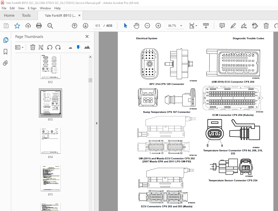
Group 20 – Diagnostic Trouble Codes 563
Group 30 – Observed Symptoms 1535
SECTION 9040 Drive Train 1591
Group 10 – Principles of Operation 1595
Group 30 – Observed Symptoms 1651
Group 40 – Tests and Adjustments 1701
SECTION 9050 Hydraulic Systems 1711
Group 10 – Principles of Operation 1715
Group 30 – Observed Symptoms 1773
Group 33 – Observed Symptoms-Gear Pump 1775
Group 35 – Observed Symptoms-Variable Displacement Pump (VDP) 1863
Group 40 – Tests and Adjustments 1907
Group 43 – Tests and Adjustments-Gear Pump 1909
Group 45 – Tests and Adjustments-Variable Displacement Pump (VDP) 1933
SECTION 9060 Operators Station 1951
Group 10 – Principles of Operation 1953
SECTION 9070 Front End (Mast) and Chassis 1989
Group 10 – Principles of Operation 1991
Group 30 – Observed Symptoms 2013
SECTION 9080 Supplementary Data 2071
Group 50 – Abbreviations and Acronyms 2073
Group 60 – Special Tools List 2081
Group 70 – Fault Mode Indicator Reference 2091
Group 80 – Supplier Specification Data 2093
524223769-2200YRM1128-(01-2023)-US-EN 2097
Series Code / Model Designation Reference Table 2105
General 2107
Deutsch Crimping Tool 2108
How to Strip a Wire for Use With Deutsch Crimping Tool 2108
How to Crimp With the Deutsch Crimping Tool 2109
Calibration Test for the Deutsch Crimping Tool 2111
Deutsch Connectors 2113
DT, DTM, and DTP Series Connectors 2113
HD Series Connectors 2156
Metri-Pack Connectors 2178
Remove and Install 2178
Micro-Pack Connectors 2181
Weather-Pack Connectors 2182
AMPSEAL Crimping Tools 2184
AMP Hand Crimping Tool With Certi-Crimp 2184
Description 2184
Stripping Wire for Use with AMP Hand Crimping Tool 2185
Insulation Crimp Adjustment 2186
Maintenance and Inspection for AMP Hand Crimping Tool 2186
AMP Hand Crimping Tool 2186
Crimp Height Inspection 2186
How to use AMP Hand Crimping Tool 2187
AMP Pro-Crimper II Tool 2187
Description 2187
Remove and Install Die Set and Locator Assembly 2188
Stripping Wire for Use With AMP PRO-CRIMPER II Tool 2188
Contact Support Adjustment 2189
Crimp Height Adjustment 2190
Maintenance and Inspection Procedures 2190
PRO-CRIMPER II Tool 2190
Crimp Height Inspection 2190
How to Use AMP PRO-CRIMPER II Tool 2191
AMPSEAL Connector Assemblies 2192
Description for Plug Connector Assembly 2192
Seal Plug 2193
Contact Crimping 2193
Description for Plug Connector and Header Assembly 2198
Voltage Reading 2201
Seal Plug 2201
Contact Crimping 2201
AMP Superseal 1 5 Crimping Tools 2208
Mini Mic Receptacle and Tab Contacts 2208
Description 2208
Crimping Conditions and Measurements 2208
Insertion of Rubber Seal on Cable 2210
AMP Hand Application Tool 2215
Description 2215
Maintenance and Inspection 2215
Crimp Height Inspection 2215
Crimp Height Adjustment 2216
How to Use AMP Hand Application Tool 2216
AMP Pro-Crimper II Tool 2217
Description 2217
Remove and Install Die Set and Locator Assembly 2217
Adjustments 2218
Contact Support 2218
Crimp Height 2219
Inspections and Maintenance 2220
Crimp Height Inspection 2220
Visual Inspection 2220
Maintenance 2221
How to Use Pro-Crimper II Tool 2221
AMP Superseal 1 5 Connector Assemblies 2222
Description 2222
Repair and Maintenance 2229
Panel Mount Option 2229
AMP Fastin-Faston Hand Tools 2230
Description – AMP Double Action Hand Tool 2230
Maintenance and Inspection Procedures 2230
Daily Maintenance 2230
Periodic Tool Inspection 2231
Lubrication 2231
Visual Inspection 2231
Crimp Height Inspection 2231
Certi-Crimp Ratchet Inspection 2232
How to Use AMP Double Action Hand Tool 2233
Description – AMP Extraction Tool 2234
Maintenance and Inspection 2235
How to Use AMP Extraction Tool 2235
AMP Fastin-Faston Receptacles and Housings 2237
Description 2237
Wire Repair 2245
Wire Splicing Requirements 2245
Deutsch Jiffy Splice 2246
Twisted/Shielded Cable and Leads Repair 2252
Special Tools 2254
524223769-2200YRM1128-(07-2020)-US-EN 2263
Series Code / Model Designation Reference Table 2269
General 2272
Deutsch Crimping Tool 2272
How to Strip a Wire for Use With Deutsch Crimping Tool 2272
How to Crimp With the Deutsch Crimping Tool 2273
Calibration Test for the Deutsch Crimping Tool 2275
Deutsch Connectors 2277
DT, DTM, and DTP Series Connectors 2277
HD Series Connectors 2319
Metri-Pack Connectors 2342
Remove and Install 2342
Micro-Pack Connectors 2344
Weather-Pack Connectors 2345
AMPSEAL Crimping Tools 2347
AMP Hand Crimping Tool With Certi-Crimp 2347
Description 2347
Stripping Wire for Use with AMP Hand Crimping Tool 2347
Insulation Crimp Adjustment 2348
Maintenance and Inspection for AMP Hand Crimping Tool 2348
AMP Hand Crimping Tool 2348
Crimp Height Inspection 2348
How to use AMP Hand Crimping Tool 2349
AMP Pro-Crimper II Tool 2349
Description 2349
Remove and Install Die Set and Locator Assembly 2350
Stripping Wire for Use With AMP PRO-CRIMPER II Tool 2351
Contact Support Adjustment 2351
Crimp Height Adjustment 2352
Maintenance and Inspection Procedures 2352
PRO-CRIMPER II Tool 2352
Crimp Height Inspection 2352
How to Use AMP PRO-CRIMPER II Tool 2353
AMPSEAL Connector Assemblies 2354
Description for Plug Connector Assembly 2354
Seal Plug 2355
Contact Crimping 2355
Description for Plug Connector and Header Assembly 2360
Voltage Reading 2362
Seal Plug 2362
Contact Crimping 2362
AMP Superseal 1 5 Crimping Tools 2369
Mini Mic Receptacle and Tab Contacts 2369
Description 2369
Crimping Conditions and Measurements 2369
Insertion of Rubber Seal on Cable 2371
AMP Hand Application Tool 2376
Description 2376
Maintenance and Inspection 2376
Crimp Height Inspection 2376
Crimp Height Adjustment 2377
How to Use AMP Hand Application Tool 2377
AMP Pro-Crimper II Tool 2378
Description 2378
Remove and Install Die Set and Locator Assembly 2379
Adjustments 2379
Contact Support 2379
Crimp Height 2380
Inspections and Maintenance 2381
Crimp Height Inspection 2381
Visual Inspection 2381
Maintenance 2382
How to Use Pro-Crimper II Tool 2382
AMP Superseal 1 5 Connector Assemblies 2383
Description 2383
Repair and Maintenance 2390
Panel Mount Option 2390
AMP Fastin-Faston Hand Tools 2391
Description – AMP Double Action Hand Tool 2391
Maintenance and Inspection Procedures 2391
Daily Maintenance 2391
Periodic Tool Inspection 2392
Lubrication 2392
Visual Inspection 2392
Crimp Height Inspection 2392
Certi-Crimp Ratchet Inspection 2393
How to Use AMP Double Action Hand Tool 2394
Description – AMP Extraction Tool 2395
Maintenance and Inspection 2395
How to Use AMP Extraction Tool 2396
AMP Fastin-Faston Receptacles and Housings 2397
Description 2397
Wire Repair 2404
Wire Splicing Requirements 2404
Deutsch Jiffy Splice 2405
Twisted/Shielded Cable and Leads Repair 2410
Special Tools 2413
524223770-2200YRM1130-(03-2020)-US-EN 2421
General 2425
Description 2425
Dash Display Menu Access 2425
Menu Navigation 2426
Standard Display 2426
Main Menu 2426
Passwords Menu 2427
Password Administration 2427
Add Password 2427
Delete Password 2428
Edit Password 2428
Other Password Functions 2429
Operator Passwords – Enable/Disable 2429
Password Time-Out Delay 2429
Passwords – Number Wrong to Disable 2430
Lockout Reset Password 2430
View Password Log 2431
View Versions 2432
VSM Versions 2432
Dash Display Versions 2433
Engine Controller Version 2434
Transmission (Xmsn) Controller Version 2435
Truck Serial Number 2436
Diagnostics 2437
View Fault Log 2437
Set Travel and Braking 2438
Speed Limit 2438
Acceleration Rate 2439
Auto-Deceleration Rate 2439
Set Power Reversal Rate 2440
Set Inching/Brake Overlap 2441
Setup Display Menu 2442
Set Operator Language 2442
Set Units 2443
Set Time Format (12/24 Hour) 2443
Set Daylight Saving Time 2443
Set Time 2446
Set Date Format 2447
Set Date 2447
Setup Hydraulics 2448
Return to Set Tilt Delay/On/Off 2448
Setup General Items 2449
Light Shutdown Time-Out 2449
Impact Sensor – Enable/Disable 2450
Impact Sensor – Soft Impact Settings 2451
Impact Sensor – Hard Impact Settings 2452
Adjust Impact Sensor Settings 2452
Initial Adjustment of Soft and Hard Impact Settings 2454
Readjustment of Soft and Hard Impact Settings 2454
Impact Sensor – Impact Alarm/Shutdown Reset 2455
Impact Sensor – Alarm Time Duration and Deactivation 2456
Impact Sensor – View Impact Event Log 2457
Engine Mode Indicator 2458
Generation 1 (ECO-eLo ONLY) 2458
Generation 2 2459
Operator Checklist 2460
Operator Checklist Off-On Mode 2460
Edit Operator Checklist 2460
Set Operator Checklist Expiration 2461
View Checklist Log 2461
Clear Operator Checklist Log 2462
Clear Operator Checklist Fault 2462
Calibrations 2463
Set Tilt Stop Point 2463
Calibrate Loaded Weight 2463
524223770-2200YRM1130-(05-2021)-US-EN 2465
General 2469
Description 2469
Dash Display Menu Access 2469
Menu Navigation 2470
Standard Display 2470
Main Menu 2470
Passwords Menu 2471
Password Administration 2471
Add Password 2471
Delete Password 2471
Edit Password 2472
Other Password Functions 2473
Operator Passwords – Enable/Disable 2473
Password Time-Out Delay 2473
Passwords – Number Wrong to Disable 2473
Lockout Reset Password 2474
View Password Log 2474
View Versions 2475
VSM Versions 2475
Dash Display Versions 2476
Engine Controller Version 2477
Transmission (Xmsn) Controller Version 2478
Truck Serial Number 2479
Diagnostics 2480
View Fault Log 2480
Set Travel and Braking 2481
Speed Limit 2481
Acceleration Rate 2482
Auto-Deceleration Rate 2482
Set Power Reversal Rate 2483
Set Inching/Brake Overlap 2484
Setup Display Menu 2485
Set Operator Language 2485
Set Units 2486
Set Time Format (12/24 Hour) 2486
Set Daylight Saving Time 2487
Set Time 2490
Set Date Format 2490
Set Date 2491
Setup Hydraulics 2492
Return to Set Tilt Delay/On/Off 2492
Setup General Items 2493
Light Shutdown Time-Out 2493
Impact Sensor – Enable/Disable 2494
Impact Sensor – Soft Impact Settings 2495
Impact Sensor – Hard Impact Settings 2495
Adjust Impact Sensor Settings 2496
Initial Adjustment of Soft and Hard Impact Settings 2498
Readjustment of Soft and Hard Impact Settings 2498
Impact Sensor – Impact Alarm/Shutdown Reset 2499
Impact Sensor – Alarm Time Duration and Deactivation 2500
Impact Sensor – View Impact Event Log 2501
Engine Mode Indicator 2501
Generation 1 (ECO-eLo ONLY) 2501
Generation 2 2502
Operator Checklist 2503
Operator Checklist Off-On Mode 2503
Edit Operator Checklist 2503
Set Operator Checklist Expiration 2503
View Checklist Log 2504
Clear Operator Checklist Log 2505
Clear Operator Checklist Fault 2505
Calibrations 2506
Set Tilt Stop Point 2506
Calibrate Loaded Weight 2506
524223771-2200YRM1131-(03-2020)-US-EN 2509
Series Code / Model Designation Reference Table 2515
General 2517
Description 2517
Dash Display Menu Access 2517
Menu Navigation 2518
Main Menu 2518
Passwords 2519
Adding Passwords 2519
Hourmeters 2521
View Versions 2522
VSM Versions 2522
Dash Display Versions 2523
Engine Controller Version 2524
Transmission (Xmsn) Controller Version 2525
Truck Serial Number 2526
Truck Configuration 2527
Diagnostics 2528
Clear Fault Log 2528
View Fault Log 2529
No-Run Data Display 2530
Engine Accelerator and Throttle Data Display 2530
Engine Speeds and Governor Data Display 2531
Engine Fuel and Emissions Data Display 2532
Engine General Data Display 2534
XMSN/Brake Data Display 2535
Hydraulic Data Display 2538
General Truck Data Display 2540
Set Travel and Braking 2541
Speed Limit 2541
Acceleration Rate 2542
Auto-Deceleration Rate 2543
Set Power Reversal Rate 2543
Set Inching/Brake Overlap 2544
Setup Hydraulics 2544
Lift Maximum Speed 2545
Lower Maximum Speed 2545
Tilt Maximum Speed 2546
Auxiliary Function One, Direction A, Maximum Speed 2548
Auxiliary Function One, Direction B, Maximum Speed 2550
Auxiliary Function Two, Direction A, Maximum Speed 2550
Auxiliary Function Two, Direction B, Maximum Speed 2551
Auxiliary Function Three, Direction A, Maximum Speed 2552
Auxiliary Function Three, Direction B, Maximum Speed 2552
Lift/Lower Ramp Rate 2553
Hydraulic Auxiliary Ramp Rate 2553
Return to Set Tilt Delay/On/Off 2554
Hydraulic Input Device 2555
Auxiliary Solenoid 2555
Dual Function 2556
Setup Display 2557
Set Service Language 2557
Setup General Items 2557
Motion Alarm Activation Type 2558
Light Shutdown Time-Out 2559
Restore Default Settings 2559
Restore Engine Controller Default Calibration 2560
Impact Sensor – Enable/Disable 2560
Impact Sensor – Soft Impact Settings 2561
Impact Sensor – Hard Impact Settings 2562
Adjust Impact Sensor Settings 2563
Initial Adjustment of Soft and Hard Impact Settings 2565
Readjustment of Soft and Hard Impact Settings 2565
Impact Sensor – Impact Alarm/Shutdown Reset 2566
Impact Sensor – Alarm Time Duration and Deactivation 2567
Impact Sensor – View Impact Event Log 2568
Engine Mode Indicator 2568
Generation 1 (ECO-eLo ONLY) 2568
Generation 2 2569
Diesel Particulate Filter (DPF) Display 2570
General Description 2570
Passive Regeneration Only 2570
Regeneration Level 0 2570
Auto/Active Regeneration Inhibited 2571
Auto/Active Regeneration 2571
Regeneration Level 1 2571
Parked Regeneration Request 2572
Regeneration Level 2 2572
Warning Level 2572
Regeneration Level 3 2572
Service Level 2573
Regeneration Level 4 2573
Display, Diesel Particulate Filter (DPF), Revised 2573
Operator Interface 2573
Refer to Operator Manual 2573
CAN Communication Lost 2574
Passive Regeneration Only 2574
Regeneration Level 0 2574
Auto/Active Regeneration Inhibited 2574
Auto/Active Regeneration 2575
Regeneration Level 1 2575
Idle-up Auto/Active Regeneration 2575
Parked Regeneration Request 2575
Regeneration Level 2 2575
Warning Level 2577
Regeneration Level 3 2577
Service Level 2577
Regeneration Level 4 2577
Diesel Particulate Filter (DPF) Display 2-3 5T ICE Stage V 2577
Display, Diesel Particulate Filter (DPF), Stage V Engine 2577
Operator Interface 2578
Refer to Operator Manual 2578
CAN Communication Lost 2578
Passive Regeneration Only 2578
Regeneration Level 0 2578
Auto/Active Regeneration Inhibited 2579
Auto/Active Regeneration 2579
Regeneration Level 1 2579
Idle-up Auto/Active Regeneration 2580
Parked Regeneration Request 2580
Regeneration Level 2 2580
Warning Level 2581
Regeneration Level 3 2581
Service Level 2582
Regeneration Level 4 2582
Stage V Content 2582
Emissions System Malfunction 2582
Ash Load 2582
Diesel Particulate Filter (DPF) Display with Diesel Exhaust Fluid (DEF) 2583
Operator Interface 2583
Refer to Operator Manual 2583
CAN Communication Lost 2584
Passive Regeneration Only 2584
Regeneration Level 0 2584
Auto/Active Regeneration Inhibited 2584
Auto/Active Regeneration 2585
Regeneration Level 1 2585
Idle-up Auto/Active Regeneration 2585
Parked Regeneration Request 2585
Regeneration Level 2 2585
Warning Level 2587
Regeneration Level 3 2587
Service Level 2587
Regeneration Level 4 2587
Calibrations 2588
Calibrate Transmission Valve 2590
Set Tilt Stop Point 2590
Calibrate Loaded Weight 2590
Calibrate Travel Speed Sensor 2591
Calibrate Mazda LP and Gas Accelerator Pedal 2591
524223771-2200YRM1131-(05-2021)-US-EN 2593
Series Code / Model Designation Reference Table 2599
General 2601
Description 2601
Dash Display Menu Access 2601
Menu Navigation 2602
Main Menu 2603
Passwords 2603
Adding Passwords 2603
Hourmeters 2605
View Versions 2606
VSM Versions 2606
Dash Display Versions 2607
Engine Controller Version 2608
Transmission (Xmsn) Controller Version 2609
Truck Serial Number 2610
Truck Configuration 2611
Diagnostics 2612
Clear Fault Log 2612
View Fault Log 2613
No-Run Data Display 2614
Engine Accelerator and Throttle Data Display 2615
Engine Speeds and Governor Data Display 2617
Engine Fuel and Emissions Data Display 2618
Engine General Data Display 2620
XMSN/Brake Data Display 2621
Hydraulic Data Display 2623
General Truck Data Display 2626
Set Travel and Braking 2628
Speed Limit 2628
Acceleration Rate 2629
Auto-Deceleration Rate 2629
Set Power Reversal Rate 2630
Set Inching/Brake Overlap 2630
Setup Hydraulics 2631
Lift Maximum Speed 2631
Lower Maximum Speed 2632
Tilt Maximum Speed 2632
Auxiliary Function One, Direction A, Maximum Speed 2634
Auxiliary Function One, Direction B, Maximum Speed 2637
Auxiliary Function Two, Direction A, Maximum Speed 2637
Auxiliary Function Two, Direction B, Maximum Speed 2638
Auxiliary Function Three, Direction A, Maximum Speed 2639
Auxiliary Function Three, Direction B, Maximum Speed 2639
Lift/Lower Ramp Rate 2640
Hydraulic Auxiliary Ramp Rate 2640
Return to Set Tilt Delay/On/Off 2641
Hydraulic Input Device 2642
Auxiliary Solenoid 2642
Dual Function 2643
Setup Display 2644
Set Service Language 2644
Setup General Items 2644
Motion Alarm Activation Type 2645
Light Shutdown Time-Out 2646
Restore Default Settings 2646
Restore Engine Controller Default Calibration 2647
Impact Sensor – Enable/Disable 2647
Impact Sensor – Soft Impact Settings 2648
Impact Sensor – Hard Impact Settings 2648
Adjust Impact Sensor Settings 2649
Initial Adjustment of Soft and Hard Impact Settings 2651
Readjustment of Soft and Hard Impact Settings 2651
Impact Sensor – Impact Alarm/Shutdown Reset 2652
Impact Sensor – Alarm Time Duration and Deactivation 2653
Impact Sensor – View Impact Event Log 2654
Engine Mode Indicator 2654
Generation 1 (ECO-eLo ONLY) 2654
Generation 2 2655
Diesel Particulate Filter (DPF) Display 2656
General Description 2656
Passive Regeneration Only 2656
Regeneration Level 0 2656
Auto/Active Regeneration Inhibited 2657
Auto/Active Regeneration 2657
Regeneration Level 1 2657
Parked Regeneration Request 2658
Regeneration Level 2 2658
Warning Level 2659
Regeneration Level 3 2659
Service Level 2659
Regeneration Level 4 2659
Display, Diesel Particulate Filter (DPF), Revised 2659
Operator Interface 2660
Refer to Operator Manual 2660
CAN Communication Lost 2660
Passive Regeneration Only 2660
Regeneration Level 0 2660
Auto/Active Regeneration Inhibited 2661
Auto/Active Regeneration 2661
Regeneration Level 1 2661
Idle-up Auto/Active Regeneration 2661
Parked Regeneration Request 2662
Regeneration Level 2 2662
Warning Level 2663
Regeneration Level 3 2663
Service Level 2663
Regeneration Level 4 2663
Diesel Particulate Filter (DPF) Display 2-3 5T ICE Stage V 2664
Display, Diesel Particulate Filter (DPF), Stage V Engine 2664
Operator Interface 2664
Refer to Operator Manual 2664
CAN Communication Lost 2665
Passive Regeneration Only 2665
Regeneration Level 0 2665
Auto/Active Regeneration Inhibited 2665
Auto/Active Regeneration 2666
Regeneration Level 1 2666
Idle-up Auto/Active Regeneration 2666
Parked Regeneration Request 2666
Regeneration Level 2 2666
Warning Level 2668
Regeneration Level 3 2668
Service Level 2668
Regeneration Level 4 2668
Stage V Content 2668
Emissions System Malfunction 2668
Ash Load 2669
Diesel Particulate Filter (DPF) Display with Diesel Exhaust Fluid (DEF) 2670
Operator Interface 2670
Refer to Operator Manual 2670
CAN Communication Lost 2671
Passive Regeneration Only 2671
Regeneration Level 0 2671
Auto/Active Regeneration Inhibited 2671
Auto/Active Regeneration 2672
Regeneration Level 1 2672
Idle-up Auto/Active Regeneration 2672
Parked Regeneration Request 2672
Regeneration Level 2 2672
Warning Level 2674
Regeneration Level 3 2674
Service Level 2674
Regeneration Level 4 2674
Calibrations 2675
Calibrate Transmission Valve 2677
Set Tilt Stop Point 2677
Calibrate Loaded Weight 2678
Calibrate Travel Speed Sensor 2678
Calibrate Mazda LP and Gas Accelerator Pedal 2679
524223780-8000YRM1134-(03-2020)-US-EN 2681
Series Code / Model Designation Reference Table 2687
Description 2689
Proc_Cal_001: Service Password Entry 2691
When to Perform 2691
Why Perform 2691
How to Perform 2691
Proc_Cal_002: Hydraulic Valve Calibration Warm Up and Air Bleed 2692
When to Perform 2692
Calibration Order 2692
Why Perform 2692
How to Perform 2693
Proc_Cal_003: Save and Exit 2694
When to Perform 2694
Why Perform 2694
How to Perform 2694
Proc_Cal_004: Lift Valve Output Threshold 2695
When to Perform 2695
Calibration Order 2695
Why Perform 2695
How to Perform 2696
Proc_Cal_005: Lower Valve Output Threshold 2698
When to Perform 2698
Calibration Order 2698
Why Perform 2698
How to Perform 2698
Proc_Cal_006: Tilt Back Valve Output Threshold 2701
When to Perform 2701
Calibration Order 2701
Why Perform 2701
How to Perform 2701
Proc_Cal_007: Tilt Forward Valve Output Threshold 2704
When to Perform 2704
Calibration Order 2704
Why Perform 2704
How to Perform 2704
Proc_Cal_008: Aux 1 Dir A Valve Output Threshold 2707
When to Perform 2707
Calibration Order 2707
Why Perform 2707
How to Perform 2707
Proc_Cal_009: Aux 1 Dir B Valve Output Threshold 2710
When to Perform 2710
Calibration Order 2710
Why Perform 2710
How to Perform 2710
Proc_Cal_010: Aux 2 Dir A Valve Output Threshold 2713
When to Perform 2713
Calibration Order 2713
Why Perform 2713
How to Perform 2713
Proc_Cal_011: Aux 2 Dir B Valve Output Threshold 2716
When to Perform 2716
Calibration Order 2716
Why Perform 2716
How to Perform 2716
Proc_Cal_012: Aux 3 Dir A Valve Output Threshold 2719
When to Perform 2719
Calibration Order 2719
Why Perform 2719
How to Perform 2719
Proc_Cal_013: Aux 3 Dir B Valve Output Threshold 2722
When to Perform 2722
Calibration Order 2722
Why Perform 2722
How to Perform 2722
Proc_Cal_014: Load Weight Zero Point 2726
When to Perform 2726
Calibration Order 2726
Why Perform 2726
How to Perform 2726
Proc_Cal_015: Loaded Weight Calibration 2728
When to Perform 2728
Calibration Order 2728
Why Perform 2728
How to Perform 2728
Proc_Cal_016: Transmission Valve Calibration 2731
Applicable System/Option 2731
When to Perform 2731
Calibration Order 2731
Why Perform 2731
How to Perform 2731
Proc_Cal_016A: Transmission Valve Calibration-Electronic Extended Function 2733
Applicable System/Option 2733
When to Perform 2733
Calibration Order 2733
Why Perform 2733
How to Perform 2733
Proc_Cal_016B: Trans Valve Calibration-Electronic and Electronic Extended Function 2735
Applicable System/Option 2735
When to Perform 2735
Calibration Order 2735
Why Perform 2735
How to Perform 2736
Proc_Cal_019: Mazda LP and Gas Accelerator Pedal Adjustment 2737
Required Tools 2737
When to Perform 2737
Calibration Order 2737
Why Perform 2738
How to Perform 2738
Proc_Cal_025: Hydraulic Valve Pressure Gage Installation 2739
When to Perform 2739
Why Perform 2739
How to Perform 2739
Proc_Cal_026: Travel Speed Calibration 2741
When to Perform 2741
Calibration Order 2741
Why Perform 2741
How to Perform 2741
524223780-8000YRM1134-(05-2022)-US-EN 2745
Series Code / Model Designation Reference Table 2751
Description 2754
Proc_Cal_001: Service Password Entry 2756
When to Perform 2756
Why Perform 2756
How to Perform 2756
Proc_Cal_002: Hydraulic Valve Calibration Warm Up and Air Bleed 2757
When to Perform 2757
Calibration Order 2757
Why Perform 2757
How to Perform 2757
Proc_Cal_003: Save and Exit 2759
When to Perform 2759
Why Perform 2759
How to Perform 2759
Proc_Cal_004: Lift Valve Output Threshold 2760
When to Perform 2760
Calibration Order 2760
Why Perform 2760
How to Perform 2760
Proc_Cal_005: Lower Valve Output Threshold 2763
When to Perform 2763
Calibration Order 2763
Why Perform 2763
How to Perform 2763
Proc_Cal_006: Tilt Back Valve Output Threshold 2766
When to Perform 2766
Calibration Order 2766
Why Perform 2766
How to Perform 2766
Proc_Cal_007: Tilt Forward Valve Output Threshold 2769
When to Perform 2769
Calibration Order 2769
Why Perform 2769
How to Perform 2769
Proc_Cal_008: Aux 1 Dir A Valve Output Threshold 2772
When to Perform 2772
Calibration Order 2772
Why Perform 2772
How to Perform 2772
Proc_Cal_009: Aux 1 Dir B Valve Output Threshold 2775
When to Perform 2775
Calibration Order 2775
Why Perform 2775
How to Perform 2775
Proc_Cal_010: Aux 2 Dir A Valve Output Threshold 2778
When to Perform 2778
Calibration Order 2778
Why Perform 2778
How to Perform 2778
Proc_Cal_011: Aux 2 Dir B Valve Output Threshold 2781
When to Perform 2781
Calibration Order 2781
Why Perform 2781
How to Perform 2781
Proc_Cal_012: Aux 3 Dir A Valve Output Threshold 2784
When to Perform 2784
Calibration Order 2784
Why Perform 2784
How to Perform 2784
Proc_Cal_013: Aux 3 Dir B Valve Output Threshold 2787
When to Perform 2787
Calibration Order 2787
Why Perform 2787
How to Perform 2787
Proc_Cal_014: Load Weight Zero Point 2790
When to Perform 2790
Calibration Order 2790
Why Perform 2790
How to Perform 2790
Proc_Cal_015: Loaded Weight Calibration 2792
When to Perform 2792
Calibration Order 2792
Why Perform 2792
How to Perform 2792
Proc_Cal_016: Transmission Valve Calibration 2795
Applicable System/Option 2795
When to Perform 2795
Calibration Order 2795
Why Perform 2795
How to Perform 2795
Proc_Cal_016A: Transmission Valve Calibration-Electronic Extended Function 2797
Applicable System/Option 2797
When to Perform 2797
Calibration Order 2797
Why Perform 2797
How to Perform 2797
Proc_Cal_016B: Trans Valve Calibration-Electronic and Electronic Extended Function 2800
Applicable System/Option 2800
When to Perform 2800
Calibration Order 2800
Why Perform 2800
How to Perform 2800
Proc_Cal_019: Mazda LP and Gas Accelerator Pedal Adjustment 2803
Required Tools 2803
When to Perform 2803
Calibration Order 2803
Why Perform 2803
How to Perform 2803
Proc_Cal_025: Hydraulic Valve Pressure Gage Installation 2805
When to Perform 2805
Why Perform 2805
How to Perform 2805
Proc_Cal_026: Travel Speed Calibration 2807
When to Perform 2807
Calibration Order 2807
Why Perform 2807
How to Perform 2807
550073240-1900YRM1620-(01-2023)-US-EN 2811
Proper Flushing after Major Hydraulic Repairs 2817
Introduction 2817
The Phases of Wear 2817
Causes of Hydraulic System Failure 2817
Progression of Contaminant Caused Hydraulic System Failure 2818
Hydraulic System Flushing Techniques 2818
Double Oil and Filter Change 2818
Mechanical Cleaning 2819
Cleaning of Components 2819
How to Clean Tubes and Hoses 2819
Filter Caddy 2819
Start-Up Procedure for Cleaned System 2820
Contaminated Oil Coolers 2820
Additional Filter Caddy Functions 2821
How to Handle Different Fluids 2821
Water Removal Filters 2821
Fluid Conditioning and System Flushing Procedures 2822
Operation of the Filter Caddy 2822
Filter Caddy operation 2822
Fluid Conditioning Procedure 2822
Filter Caddy Start-Up 2823
System Flushing Procedure 2823
Component Cleaning Procedure 2824
Reservoir Cleaning Procedure 2824
Cylinder Cleaning Procedure 2824
Hose and Tube Cleaning Procedure 2824
Valve Cleaning Procedure 2825
Front-End Attachment Cleaning Procedure 2826
System Flushing Procedure 2826
Filter Caddy Start-Up 2827
System Start-Up and Flushing 2827
Reservoir Fluid Cleaning Times 2828
Dealing With Different Fluid Types 2829
Cleaning Procedure After Switching Fluids (Cross Contamination Flushing) 2829
Filter Caddy Maintenance 2829
Servicing the Strainer 2829
DC Motor 2829
Hydraulic Oil Sampling Method and Procedure 2830
Hydraulic Oil Sampling Method 2830
Objective 2830
General Guidelines 2830
Synopsis 2831
Hydraulic Oil Analysis Report Guidelines 2832
Sampling Conditions 2832
Equipment 2832
Sampling Procedure 2833
Hydraulic Oil Sampling 2833
Sample Labeling 2833
Results Documentation 2833
550073240-1900YRM1620-(03-2020)-US-EN 2835
Proper Flushing after Major Hydraulic Repairs 2839
Introduction 2839
The Phases of Wear 2839
Causes of Hydraulic System Failure 2839
Progression of Contaminant Caused Hydraulic System Failure 2840
Hydraulic System Flushing Techniques 2840
Double Oil and Filter Change 2840
Mechanical Cleaning 2841
Cleaning of Components 2841
How to Clean Tubes and Hoses 2841
Filter Caddy 2841
Start-Up Procedure for Cleaned System 2842
Contaminated Oil Coolers 2842
Additional Filter Caddy Functions 2842
How to Handle Different Fluids 2842
Water Removal Filters 2843
Fluid Conditioning and System Flushing Procedures 2843
Operation of the Filter Caddy 2843
Filter Caddy operation 2843
Fluid Conditioning Procedure 2844
Filter Caddy Start-Up 2844
System Flushing Procedure 2845
Component Cleaning Procedure 2845
Reservoir Cleaning Procedure 2845
Cylinder Cleaning Procedure 2845
Hose and Tube Cleaning Procedure 2846
Valve Cleaning Procedure 2846
Front-End Attachment Cleaning Procedure 2847
System Flushing Procedure 2847
Filter Caddy Start-Up 2848
System Start-Up and Flushing 2848
Reservoir Fluid Cleaning Times 2849
Dealing With Different Fluid Types 2849
Cleaning Procedure After Switching Fluids (Cross Contamination Flushing) 2849
Filter Caddy Maintenance 2850
Servicing the Strainer 2850
DC Motor 2850
Hydraulic Oil Sampling Method and Procedure 2850
Hydraulic Oil Sampling Method 2850
Objective 2850
General Guidelines 2850
Synopsis 2851
Hydraulic Oil Analysis Report Guidelines 2852
Sampling Conditions 2853
Equipment 2853
Sampling Procedure 2853
Hydraulic Oil Sampling 2853
Sample Labeling 2854
Results Documentation 2854
550093750-2100YRM1668-(02-2018)-US-EN 2857
General 2861
Safety Procedures When Working Near Mast 2862
Main Lift Cylinder Repair 2864
Remove 2864
Disassemble 2866
Clean 2868
Inspect 2868
Assemble 2868
Install 2869
Main Lift Cylinder Leak Check 2869
Free-Lift Cylinder 2870
Remove 2870
Disassemble 2871
Clean 2873
Inspect 2873
Assemble 2873
Install 2873
Tilt Cylinder Repair 2874
Remove 2874
Disassemble 2876
Clean 2878
Inspect 2878
Assemble 2878
Install 2879
Tilt Cylinder Adjustment 2880
Tilt Cylinder Leak Check 2881
Integral Sideshift Cylinder Repair Prior to December 2016 2883
Remove 2883
Disassemble 2884
Clean 2885
Inspect 2885
Assemble 2885
Install 2885
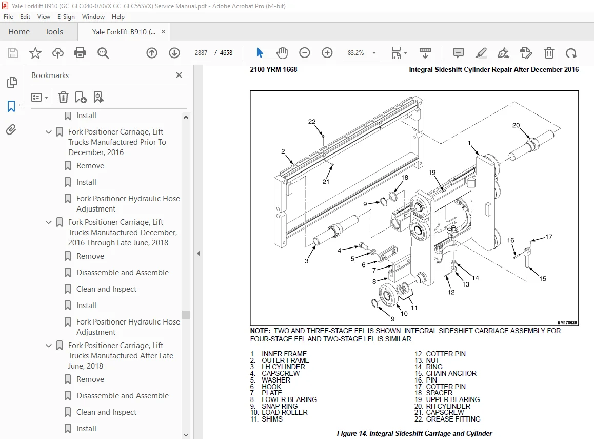
Integral Sideshift Cylinder Repair After December 2016 2886
General 2886
Remove 2886
Disassemble 2888
Clean 2888
Inspect 2888
Assemble 2888
Install 2889
Integral Side-Shift Cylinder Gland Leak Checks 2890
Fork Positioner Cylinder Repair Prior to December 2016 2891
Remove 2891
Disassemble 2891
Clean 2893
Inspect 2894
Assemble 2894
Install 2894
Fork Positioner Cylinder Adjustment 2894
Fork Positioner Cylinder Repair After December 2016 2895
General 2895
Remove 2895
Disassemble 2895
Clean 2898
Inspect 2899
Assemble 2899
Install 2899
Fork Positioner Cylinder Adjustment 2899
Seal Kit Installation 2900
External Installation (Seal and Backup Ring) 2900
Internal Installation (Piston Rod Assembly) 2900
Torque Specifications 2901
Main Lift Cylinders 2901
Free-Lift Cylinder 2901
Tilt Cylinders 2901
Integral Sideshift Cylinder 2901
Fork Positioner Cylinder 2901
550093750-2100YRM1668-(04-2023)-US-EN 2905
General 2911
Safety Procedures When Working Near Mast 2914
Main Lift Cylinder Repair 2916
Remove 2916
Disassemble 2918
Clean 2920
Inspect 2920
Assemble 2920
Install 2921
Main Lift Cylinder Leak Check 2921
Free-Lift Cylinder 2922
Remove 2922
Disassemble 2923
Clean 2925
Inspect 2925
Assemble 2925
Install 2925
Tilt Cylinder Repair 2927
Remove 2927
Disassemble 2929
Clean 2930
Inspect 2931
Assemble 2931
Install 2932
Tilt Cylinder Adjustment 2932
Tilt Cylinder Leak Check 2934
Integral Sideshift Cylinder Repair Prior to December 2016 2936
Remove 2936
Disassemble 2936
Clean 2937
Inspect 2937
Assemble 2937
Install 2938
Integral Sideshift Cylinder Repair After December 2016 2939
General 2939
Remove 2939
Disassemble 2940
Clean 2941
Inspect 2941
Assemble 2941
Install 2941
Integral Side-Shift Cylinder Gland Leak Checks 2942
Fork Positioner Cylinder Repair Prior to December 2016 2943
Remove 2943
Disassemble 2943
Clean 2946
Inspect 2946
Assemble 2947
Install 2947
Fork Positioner Cylinder Adjustment 2947
Fork Positioner Cylinder Repair After December 2016 2949
General 2949
Remove 2949
Disassemble 2949
Clean 2952
Inspect 2952
Assemble 2953
Install 2953
Fork Positioner Cylinder Adjustment 2953
Seal Kit Installation 2955
External Installation (Seal and Backup Ring) 2955
Internal Installation (Piston Rod Assembly) 2955
Torque Specifications 2956
Main Lift Cylinders 2956
Free-Lift Cylinder 2956
Tilt Cylinders 2956
Integral Sideshift Cylinder 2956
Fork Positioner Cylinder 2956
550093755-4000YRM1669-(04-2023)-US-EN 2959
General 2967
Safety Procedures When Working Near Mast 2969
Fork Replacement 2971
Standard Carriage and Integral Sideshift Carriage 2971
Remove 2971
Install 2972
Checks 2972
Fork Positioner Carriage 2974
Remove 2975
Install 2975
Checks 2977
Carriages Repair, Two-Stage LFL Mast 2980
Standard Carriage 2980
Remove 2980
Clean and Inspect 2981
Install 2981
Integral Sideshift Carriage, Lift Trucks Manufactured Prior To December, 2016 2981
Remove 2981
Disassemble 2983
Clean and Inspect 2984
Assemble 2985
Install 2985
Integral Sideshift Carriage, Lift Trucks Manufactured December, 2016 through Late June, 2018 2986
Remove 2986
Disassemble 2989
Clean and Inspect 2989
Assemble 2990
Install 2991
Integral Sideshift Carriage, Lift Trucks Manufactured Late June, 2018 and After 2991
Remove 2991
Disassemble 2994
Clean and Inspect 2994
Assemble 2995
Install 2996
Fork Positioner Carriage, Lift Trucks Manufactured Prior To December, 2016 2996
Remove 2996
Install 2998
Fork Positioner Hydraulic Hose Adjustment 3000
Fork Positioner Carriage, Lift Trucks Manufactured December, 2016 Through Late June, 2018 3001
Remove 3001
Disassemble and Assemble 3005
Clean and Inspect 3005
Install 3005
Fork Positioner Hydraulic Hose Adjustment 3006
Fork Positioner Carriage, Lift Trucks Manufactured Late June, 2018 and After 3007
Remove 3007
Disassemble and Assemble 3011
Clean and Inspect 3011
Install 3011
Fork Positioner Hydraulic Hose Adjustment 3012
Two-Stage LFL Mast Repair 3014
Mast With Serial Number F507 3014
Remove 3014
Disassemble 3018
Clean and Inspect 3025
Assemble 3027
Install 3028
Header Hoses 3030
Remove 3030
Installation 3030
Adjustment 3034
Mast With Serial Number F562 3035
Remove 3035
Disassemble 3039
Clean and Inspect 3046
Assemble 3048
Install 3049
Header Hose Installation and Adjustment 3050
Remove 3050
Installation 3051
Adjustment 3055
Carriages Repair, Three-Stage FFL Mast 3057
Standard Carriage 3057
Remove 3057
Clean and Inspect 3058
Install 3059
Integral Sideshift Carriage, Lift Trucks Manufactured Prior To December, 2016 3059
Remove 3059
Disassemble 3060
Clean and Inspect 3061
Assemble 3062
Install 3062
Integral Sideshift Carriage, Lift Trucks Manufactured December, 2016 Through Late June, 2018 3063
Remove 3063
Disassemble 3065
Clean and Inspect 3066
Assemble 3067
Install 3067
Integral Sideshift Carriage, Lift Trucks Manufactured Late June, 2018 and After 3068
Remove 3068
Disassemble 3070
Clean and Inspect 3071
Assemble 3072
Install 3072
Fork Positioner Carriage, Lift Trucks Manufactured Prior To December, 2016 3073
Remove 3073
Install 3075
Fork Positioner Hydraulic Hose Adjustment 3077
Fork Positioner Carriage, Lift Trucks Manufactured December, 2016 Through Late June, 2018 3078
Remove 3078
Disassemble and Assemble 3080
Clean and Inspect 3080
Install 3080
Fork Positioner Hydraulic Hose Adjustment 3081
Fork Positioner Carriage, Lift Trucks Manufactured After Late June, 2018 3082
Remove 3082
Disassemble and Assemble 3085
Clean and Inspect 3085
Install 3085
Fork Positioner Hydraulic Hose Adjustment 3086
Three-Stage FFL Mast Repair 3088
Mast With Serial Number F508 3088
Remove 3088
Disassemble 3091
Clean and Inspect 3101
Assemble 3104
Install 3105
Header Hose Installation and Adjustment 3107
Remove 3107
Installation 3107
Adjustment 3116
Mast With Serial Number F563 3116
Remove 3116
Disassemble 3120
Clean and Inspect 3130
Assemble 3133
Install 3134
Header Hose Installation and Adjustment 3136
Remove 3136
Installation 3136
Adjustment 3144
Mast Adjustments 3146
Load Roller, Adjust 3146
Mast Side Kicking, Adjust 3148
Carriage Adjustments 3149
Lift Chains Adjustment 3151
Hydraulic Quick Disconnect Hoses 3153
Disconnecting Attachment Hydraulic Quick Disconnect Hoses, Lift Truck Models GLC020-35VX (GC/GLC040-070VX, GC/GLC055SVX) (A910, B910, C910) and GLP/GDP20-35VX (CP/CLP/CDP040-070VX) (B875, C875, D875) 3153
Lift Trucks Equipped With E-Hydraulic Controls 3153
Lift Trucks Equipped With Manual Hydraulic Controls 3153
Connecting Attachment Hydraulic Quick Disconnect Hoses, Lift Truck Models GLC020-35VX (GC/GLC040-070VX, GC/GLC055SVX) (A910, B910, C910) and GLP/GDP20-35VX (CP/CLP/CDP040-070VX) (B875, C875, D875) 3154
Lift Trucks Equipped With E-Hydraulic Controls 3154
Lift Trucks Equipped With Manual Hydraulic Controls 3154
Disconnecting Attachment Hydraulic Quick Disconnect Hoses, Lift Truck Models ERC22-35VG (ERC045-070VG) (A968) and ERP22-35VL (ERP045-070VL) (A976) 3154
Connecting Attachment Hydraulic Quick Disconnect Hoses, Lift Truck Models ERC22-35VG (ERC045-070VG) (A968) and ERP22-35VL (ERP045-070VL) (A976) 3154
550093755-4000YRM1669-(06-2019)-US-EN 3157
General 3163
Safety Procedures When Working Near Mast 3164
Fork Replacement 3166
Standard Carriage and Integral Sideshift Carriage 3166
Remove 3166
Install 3168
Checks 3168
Fork Positioner Carriage 3170
Remove 3171
Install 3171
Checks 3173
Carriages Repair, Two-Stage LFL Mast 3175
Standard Carriage 3175
Remove 3175
Clean and Inspect 3176
Install 3177
Integral Sideshift Carriage, Lift Trucks Manufactured Prior To December, 2016 3177
Remove 3177
Disassemble 3178
Clean and Inspect 3179
Assemble 3180
Install 3180
Integral Sideshift Carriage, Lift Trucks Manufactured December, 2016 through Late June, 2018 3181
Remove 3181
Disassemble 3184
Clean and Inspect 3184
Assemble 3185
Install 3185
Integral Sideshift Carriage, Lift Trucks Manufactured Late June, 2018 and After 3186
Remove 3186
Disassemble 3189
Clean and Inspect 3189
Assemble 3190
Install 3190
Fork Positioner Carriage, Lift Trucks Manufactured Prior To December, 2016 3191
Remove 3191
Install 3193
Fork Positioner Hydraulic Hose Adjustment 3195
Fork Positioner Carriage, Lift Trucks Manufactured December, 2016 Through Late June, 2018 3196
Remove 3196
Disassemble and Assemble 3200
Clean and Inspect 3200
Install 3200
Fork Positioner Hydraulic Hose Adjustment 3201
Fork Positioner Carriage, Lift Trucks Manufactured Late June, 2018 and After 3202
Remove 3202
Disassemble and Assemble 3206
Clean and Inspect 3206
Install 3206
Fork Positioner Hydraulic Hose Adjustment 3207
Two-Stage LFL Mast Repair 3208
Mast With Serial Number F507 3208
Remove 3208
Disassemble 3212
Clean and Inspect 3219
Assemble 3221
Install 3222
Header Hoses 3224
Remove 3224
Installation 3224
Adjustment 3228
Mast With Serial Number F562 3229
Remove 3229
Disassemble 3233
Clean and Inspect 3240
Assemble 3242
Install 3243
Header Hose Installation and Adjustment 3244
Remove 3244
Installation 3245
Adjustment 3249
Carriages Repair, Three-Stage FFL Mast 3250
Standard Carriage 3250
Remove 3250
Clean and Inspect 3252
Install 3252
Integral Sideshift Carriage, Lift Trucks Manufactured Prior To December, 2016 3252
Remove 3252
Disassemble 3254
Clean and Inspect 3255
Assemble 3256
Install 3256
Integral Sideshift Carriage, Lift Trucks Manufactured December, 2016 Through Late June, 2018 3257
Remove 3257
Disassemble 3259
Clean and Inspect 3260
Assemble 3261
Install 3261
Integral Sideshift Carriage, Lift Trucks Manufactured Late June, 2018 and After 3262
Remove 3262
Disassemble 3264
Clean and Inspect 3265
Assemble 3266
Install 3266
Fork Positioner Carriage, Lift Trucks Manufactured Prior To December, 2016 3267
Remove 3267
Install 3269
Fork Positioner Hydraulic Hose Adjustment 3271
Fork Positioner Carriage, Lift Trucks Manufactured December, 2016 Through Late June, 2018 3272
Remove 3272
Disassemble and Assemble 3274
Clean and Inspect 3274
Install 3274
Fork Positioner Hydraulic Hose Adjustment 3275
Fork Positioner Carriage, Lift Trucks Manufactured After Late June, 2018 3276
Remove 3276
Disassemble and Assemble 3279
Clean and Inspect 3279
Install 3279
Fork Positioner Hydraulic Hose Adjustment 3280
Three-Stage FFL Mast Repair 3281
Mast With Serial Number F508 3281
Remove 3281
Disassemble 3285
Clean and Inspect 3295
Assemble 3298
Install 3299
Header Hose Installation and Adjustment 3301
Remove 3301
Installation 3301
Adjustment 3309
Mast With Serial Number F563 3310
Remove 3310
Disassemble 3313
Clean and Inspect 3323
Assemble 3326
Install 3327
Header Hose Installation and Adjustment 3329
Remove 3329
Installation 3329
Adjustment 3337
Mast Adjustments 3338
Load Roller, Adjust 3338
Mast Side Kicking, Adjust 3340
Carriage Adjustments 3340
Lift Chains Adjustment 3342
Hydraulic Quick Disconnect Hoses 3344
Disconnecting Attachment Hydraulic Quick Disconnect Hoses, Lift Truck Models GLC020-35VX (GC/GLC040-070VX, GC/GLC055SVX) (A910, B910, C910) and GLP/GDP20-35VX (CP/CLP/CDP040-070VX) (B875, C875, D875) 3344
Lift Trucks Equipped With E-Hydraulic Controls 3344
Lift Trucks Equipped With Manual Hydraulic Controls 3345
Connecting Attachment Hydraulic Quick Disconnect Hoses, Lift Truck Models GLC020-35VX (GC/GLC040-070VX, GC/GLC055SVX) (A910, B910, C910) and GLP/GDP20-35VX (CP/CLP/CDP040-070VX) (B875, C875, D875) 3345
Lift Trucks Equipped With E-Hydraulic Controls 3345
Lift Trucks Equipped With Manual Hydraulic Controls 3346
Disconnecting Attachment Hydraulic Quick Disconnect Hoses, Lift Truck Models ERC22-35VG (ERC045-070VG) (A968) and ERP22-35VL (ERP045-070VL) (A976) 3346
Connecting Attachment Hydraulic Quick Disconnect Hoses, Lift Truck Models ERC22-35VG (ERC045-070VG) (A968) and ERP22-35VL (ERP045-070VL) (A976) 3346
550096306-8000YRM1687-(11-2017)-US-EN 3349
General 3355
Serial Number Data 3355
How to Move Disabled Lift Truck 3356
How to Tow Lift Truck 3356
How to Put Lift Truck on Blocks 3356
How to Raise Drive Tires 3356
How to Raise Steering Tires 3357
How to Clean a Lift Truck 3358
Maintenance Schedule 3358
Maintenance Procedures Every 8 Hours or Daily 3370
How to Make Checks With Engine Stopped 3371
Tires and Wheels 3371
Safety Labels 3372
Mast, Carriage, Lift Chains, Header Hoses, Attachment 3372
Operator Restraint System 3373
Emergency Locking Retractor (ELR) 3374
Adjust Seat – Full Suspension 3374
Adjust Seat – Internal Suspension 3375
Hood and Seat Latches 3376
Engine Compartment 3376
Paper Application 3376
Fuel, Oil, and Coolant Leaks, Check 3377
Hydraulic Hoses 3377
Coolant Hoses 3377
Steering Column Gas Cylinder 3377
Transmission 3377
Hydraulic System Oil 3377
Engine Oil 3378
Air Filter 3381
Forks 3381
Remove 3381
Inspect 3383
Install 3384
Adjust 3384
Forks 3384
Remove 3384
Inspect 3385
How to Make Checks With Engine Running 3386
Indicator Lights, Horn, Fuses, and Relays 3386
Service Brakes 3388
Brake Fluid Level 3388
Operation, Check 3389
Parking Brake 3389
Engine Oil Pressure 3389
Cooling System 3390
Steering System 3391
Control Levers and Pedals 3391
Lift System, Operate 3391
First Service After First 100 Hours of Operation 3391
Mazda and Kubota Engine Oil and Oil Filter 3392
Yanmar Engine Oil and Oil Filter 3393
Maintenance Procedures Every 250 Hours or 6 Months 3393
Mazda Engine Oil and Oil Filter 3393
Drive Belt 3394
Mazda 2 2L Engines 3394
Fan and Alternator Drive Belt 3394
Kubota 2 5L Engine 3394
Fan and Alternator Drive Belt 3394
Maintenance Procedures Every 500 Hours or 6 Months 3394
Kubota Engine Oil and Oil Filter 3395
Hydraulic System Oil 3395
Hydraulic Tank Breather 3396
Inspect 3396
Battery 3396
Yanmar Engine Oil and Oil Filter 3397
Drive Belt 3398
Yanmar Diesel Engine 3398
Fan and Alternator Drive Belt 3398
PCV Valve, Mazda Engines 3399
Clean Debris From Radiator Core 3399
Transmission Oil Level 3399
Wet Brake Planetary Housing Oil Level Check 3401
Forks 3403
Mast Lubrication 3403
Header Hose Checks 3406
Lift Chain Lubrication 3406
Tilt Cylinder Lubrication 3406
Master Brake Cylinder Rod End Pin Lubrication 3408
Manual Hydraulic Levers Lubrication 3408
Brake Fluid 3409
Tie Rod Lubrication (GP/GLP/GDP040-070VX) 3410
Differential and Drive Axle Oil (Dry Brake) 3410
Maintenance Procedures Every 1000 Hours or 6 Months 3410
Valve Clearance, Check and Adjust 3411
PCV Valve, Kubota Engine 3411
Ignition System 3411
Mazda 2 2L Engines 3411
LPG Fuel Filter Element Replace, Kubota 2 5L Engine 3411
Remove 3411
Install 3412
LPG Vapor Fuel Filter Replace, Mazda Engines 3412
Gasoline Fuel Filter Replacement, Mazda Engines 3413
Remove and Replace 3413
Fuel Filter Replacement, Yanmar Engine 3413
Priming the Fuel System (Yanmar) 3415
Lift Chains Wear Check 3416
Lift Chain Lubrication 3416
Integral Sideshift Carriage, Check Bearings 3417
Integral Sideshift Carriage, Check Lower Mounting Hooks 3417
Steering Axle 3418
Control Levers and Pedals 3418
Maintenance Procedures Every 2000 Hours or Annually 3418
Hydraulic System 3419
Hydraulic Filter, Replace 3419
Hydraulic Tank Breather, Replace 3420
Air Filter 3421
Ignition System 3422
Kubota 2 5L Engine 3422
PCV Valve 3422
Oxygen Sensor 3422
Timing Belt 3423
Mazda Engines 3423
Gasoline Fuel Injector, Mazda Engines 3423
Fuel Injector, Yanmar Engines 3423
Forks 3423
Integral Sideshift Carriage 3423
Bearings, Replace 3423
Transmission Oil and Filter (Dry Brake), Replace 3423
Iron Transmission Housing 3423
Aluminum Transmission Housing 3425
Remove 3425
Clean and Inspect 3426
Install 3426
Transmission Oil Change, Wet Brake Drive Axle 3426
Iron Transmission Housing 3426
Aluminum Transmission Housing 3427
Wet Brake Axle Center Section and Planetary Housing, Oil Change 3430
Brake Fluid (Master Cylinder), Change 3433
Brake Fluid (Dry Brake), Remove 3434
Service Brakes (Dry Brake) 3434
Differential (Dry Brake) 3435
Steering Axle Wheel Bearing Lubrication 3436
Maintenance Procedures Every 4000 Hours or 2 Years 3436
Hydraulic Oil, Replace 3436
Cooling System 3436
Safety Procedures When Working Near Mast 3437
Hood Latch Check 3440
Lift Chain Adjustments 3441
Jump-Starting the Lift Truck 3443
Jump-Starting Using a Battery Charger 3443
Jump-Starting a Lift Truck Using Another Lift Truck 3443
Welding Repairs 3443
Wheel and Tire Replacement 3444
General 3444
Solid Rubber Tire, Change ( Series)GC/GLC 3444
Remove and Install Tire on Wheel 3445
Pneumatic Tire With Tube, Repair 3446
Remove Wheels From Lift Truck 3446
Remove Tire From Wheel 3446
Install Wheel in Tire 3449
Install Tire on Two-Piece Wheel 3451
Add Air to Pneumatic Tires With Tube 3452
Install the Wheels 3453
Dual Drive Wheels, Install 3453
Pneumatic Tubeless Tire, Repair 3454
Remove Wheels From Lift Truck 3454
Add Air to Pneumatic Tubeless Tire 3459
Wheels, Install 3459
Solid Rubber Tires on Pneumatic Wheels, Change 3459
Overhead Guard Changes 3463
Adhesives and Sealants 3463
550096314-0100YRM1672-(04-2014)-US-EN 3467
550096315-0600YRM1673-(04-2014)-US-EN 3539
550096316-0600YRM1670-(07-2019)-US-EN 3579
General 3583
Fan Belt Installation 3583
Remove 3583
Inspect 3583
Installation 3584
Thermostat Repair 3584
Remove 3584
Thermostat Operation Check 3585
Install 3585
Water Pump Repair 3585
Remove 3585
Clean and Inspect 3585
Install 3586
Lubrication System Repair 3586
Oil Pan and Oil Pickup, Remove 3586
Oil Pan and Oil Pickup, Inspection 3586
Oil Pump, Remove 3587
Oil Pump, Inspection 3587
Rotor Lobe Clearance 3587
Rotor Cover Clearance 3588
Oil Pump, Assemble and Install 3588
Oil Pan and Oil Pickup, Assemble and Install 3588
Cylinder Head Repair 3589
Remove and Disassemble 3589
Clean and Inspect 3592
Valve Guides and Seats 3594
Valve Lapping 3594
Valve Guide, Replacement 3594
Valve Seats, Inspection and Repair 3595
Valve and Valve Seat Correction 3595
Valve Springs 3596
Assemble and Install 3597
Valve Clearance Adjustments 3600
Gear Case, Timing Gears, and Camshaft 3602
Gear Case 3602
Fan Drive Pulley, Remove 3602
Fan Drive Pulley, Install 3603
Gear Case, Remove 3603
Gear Case, Install 3603
Timing Gears 3603
Oil Pump, Remove 3603
Oil Pump, Install 3603
Crankshaft Oil Slinger, Remove 3603
Crankshaft Oil Slinger, Install 3604
Idler Gear, Remove 3604
Idler Gear, Install 3604
Camshaft 3604
Camshaft, Remove 3604
Camshaft, Install 3605
Piston and Connecting Rod Assemblies Repair 3605
Disassemble 3605
Piston, Clean and Inspect 3606
Piston Ring Gap 3606
Piston Ring Groove 3607
Connecting Rod and Piston Pin, Clean and Inspect 3607
Cylinder Bores, Clean and Inspect 3608
Cylinder Correction (Oversize) 3610
Assemble 3610
Piston Bore Preparation 3612
Cylinder Wear 3612
Cylinder Correction (Oversize) 3612
Flywheel and Bearing Case Cover 3613
Flywheel, Remove 3613
Bearing Case Cover, Remove 3613
Bearing Case Cover, Install 3614
Flywheel, Install 3614
Crankshaft Repair 3615
Crankshaft, Remove 3615
Inspect and Repair 3616
Crankshaft Journal Oil Clearance Bearing 1 3616
Crankshaft Journal Oil Clearance Bearing 2 3617
Crankshaft Bend 3618
Crankshaft, Install 3618
Crankshaft Side Clearance 3620
Engine Block Cleaning and Inspection 3621
Clean and Inspect 3621
Engine Removal and Installation 3622
Engine Specifications 3622
Engine Data 3622
Torque Specifications 3623
550096317-0700YRM1674-(03-2014)-US-EN 3625
550096318-0900YRM1675-(04-2018)-US-EN 3651
General 3655
LPG Tank and Bracket Replacement 3655
Remove LPG Tank 3655
Install LPG Tank 3658
Remove LPG Bracket 3658
Install LPG Bracket 3661
Remove LPG Tank Bracket Alignment Pin 3661
Install LPG Tank Bracket Alignment Pin 3663
Fuel Filter Unit Repair 3664
Fuel Filter Element 3664
Remove 3664
Clean/Inspect 3665
Install 3665
Fuel Filter Housing 3665
Remove 3665
Disassemble 3667
Assemble 3668
Install 3668
Electronic Throttle Body Repair 3669
Remove 3669
Install 3670
Electronic Pressure Regulator (EPR) Repair 3671
Remove 3671
Disassemble 3673
Assemble 3676
Install 3677
LPG Shutoff Valve Assembly 3677
Remove 3677
Install 3679
Fuel Mixer Repair 3680
Remove 3680
Install 3682
Control System 3684
Engine Control Unit (ECU) 3684
Remove 3684
Install 3685
Low LPG Pressure Switch 3686
Remove 3686
Install 3687
LPG Low Level Sensor 3687
Remove 3687
Install 3689
Exhaust System 3690
Counterweight Exhaust System 3690
Remove and Disassemble 3690
Inspect 3692
Assemble and Install 3692
Overhead Exhaust System 3692
Remove and Disassemble 3692
Inspect 3695
Assemble and Install 3695
Exhaust Manifold 3695
Remove 3695
Install 3697
Positive Crankcase Ventilation (PCV) Valve 3697
Remove 3697
Inspect 3697
Install 3697
Oxygen Sensor 3697
Remove 3697
Install 3698
LPG Fuel Testing 3699
General 3699
Available Fuel Tests 3699
Composition Test (ASTM D-2163) 3699
Ammonia Test (ASTM D-4490) 3699
Basic Nitrogen Test (ASTM UOP269-90) 3699
Residues Test (ASTM D-2158) 3699
Vapor Pressure Test (ASTM D-2598) 3699
Sulfur Compounds Test (ASTM D-5623) 3699
Methanol Test (ASTM D-4864) 3700
Copper Corrosion (ASTM D-1838) 3700
Where To Send LPG Fuel Samples For Testing 3700
550096319-0900YRM1676-(04-2014)-US-EN 3703
550096320-0900YRM1677-(04-2018)-US-EN 3731
General 3735
LPG Tank and Bracket Replacement 3735
Remove LPG Tank 3735
Install LPG Tank 3738
Remove LPG Bracket 3738
Install LPG Bracket 3741
Remove LPG Tank Bracket Alignment Pin 3741
Install LPG Tank Bracket Alignment Pin 3743
LPG Fuel Filter Unit Repair 3744
LPG Fuel Filter Element 3744
Remove/Disassemble 3744
Clean/Inspect 3745
Assemble/Install 3745
Fuel Filter Housing 3746
Remove 3746
Disassemble 3749
Clean and Inspect 3750
Assemble 3750
Install 3751
Electronic Throttle Body Repair 3751
Remove 3752
Install 3753
LPG Fuel Mixer With Direct Electronic Pressure Regulator (DEPR) Repair 3754
Remove 3754
Install 3755
Control System 3756
Engine Control Unit (ECU) 3756
Remove 3756
Install 3757
Low LPG Pressure Switch 3757
Remove 3757
Install 3758
LPG Low Level Sensor 3758
Remove 3759
Install 3760
LPG Converter 3761
Remove 3761
Install 3764
LPG Lock-Off Valve 3765
Remove 3765
Install 3767
Exhaust System 3768
Counterweight Exhaust System 3768
Lift Truck Models GLC20-35VX (GLC040-070VX, GLC055SVX) (B910, C910) 3768
Remove and Disassemble 3768
Inspect 3769
Assemble and Install 3769
Lift Truck Models GLP20-35VX (GLP040-070VX) (C875, D875) 3770
Remove and Disassemble 3770
Inspect 3771
Assemble and Install 3772
Overhead Exhaust System 3772
Remove and Disassemble 3772
Inspect 3773
Assemble and Install 3774
Exhaust Manifold 3774
Remove 3774
Install 3775
Oxygen (HEGO) Sensor 3775
Remove 3775
Install 3776
PCV Valve 3776
LPG Fuel Testing 3777
General 3777
Available Fuel Tests 3777
Composition Test (ASTM D-2163) 3777
Ammonia Test (ASTM D-4490) 3777
Basic Nitrogen Test (ASTM UOP269-90) 3777
Residues Test (ASTM D-2158) 3777
Vapor Pressure Test (ASTM D-2598) 3777
Sulfur Compounds Test (ASTM D-5623) 3777
Methanol Test (ASTM D-4864) 3778
Copper Corrosion (ASTM D-1838) 3778
Where To Send LPG Fuel Samples For Testing 3778
550096321-1300YRM1678-(04-2014)-US-EN 3781
550096323-1400YRM1680-(01-2023)-US-EN 3849
General 3855
Drive Axle Repair 3855
Remove and Disassemble 3855
Clean and Inspect 3858
Assemble and Install 3858
Differential Repair 3862
Remove 3862
Disassemble 3874
Clean and Inspect 3881
Install 3892
Pinion Inner Shim Set, Adjust Thickness (Depth of Pinion) 3892
Ring Gear Backlash, Adjust 3909
Ring Gear, Runout Check 3911
Gear Set, Tooth Contact Pattern Check 3911
Torque Specifications 3914
550096323-1400YRM1680-(04-2014)-US-EN 3917
550096324-1600YRM1681-(04-2014)-US-EN 3979
550096325-1800YRM1682-(04-2014)-US-EN 4003
550096326-1900YRM1683-(04-2014)-US-EN 4037
550096327-2000YRM1684-(01-2016)-US-EN 4071
General 4075
Electro-Hydraulic Main Control Valve 4076
Description 4076
Remove 4079
Electro-Hydraulic Control Valve Sections 4081
General 4081
Outlet Control Valve Section 4082
Remove 4082
Disassemble 4082
Clean 4084
Inspect 4084
Assemble 4084
Install 4085
Auxiliary Control Valve Sections 4085
Remove 4085
Disassemble 4086
Clean 4086
Inspect 4087
Assemble 4087
Install 4087
Tilt Control Valve Section 4087
Remove 4087
Disassemble 4088
Clean 4089
Inspect 4089
Assemble 4089
Install 4089
Lift/Lower Control Valve Section 4089
Remove 4089
Disassemble 4089
Clean 4091
Inspect 4091
Assemble 4092
Install 4093
Install 4093
Electro Hydraulic Poppet Valve (EHPV) Pilot Pin Adjustment 4095
Lift Pilot Pin 4095
Lower Pilot Pin 4097
Abnormal/Erroneous EHPV Adjustment 4099
Manual Main Control Valve 4099
Description 4099
Remove 4102
OPS Solenoid Assembly 4108
General 4108
Remove 4109
Clean and Inspect 4112
Install 4112
Manual Control Valve Sections 4113
General 4113
Outlet Control Valve Section 4113
Remove 4113
Disassemble 4113
Clean 4116
Inspect 4116
Assemble 4116
Install 4117
Auxiliary Control Valve Sections 4117
Remove 4117
Disassemble 4117
Clean 4120
Inspect 4120
Assemble 4120
Install 4121
Lift/Tilt Control Valve Section 4121
Remove 4121
Disassemble 4121
Clean 4124
Inspect 4124
Assemble 4125
Install 4125
Install 4125
Pressure Relief Valve Check and Adjustment 4130
Primary Relief Valve 4131
Secondary Relief Valve 4131
Steering Control Unit Repair 4132
Steering Control Unit, Remove 4132
Steering Control Unit, Disassemble 4132
Steering Control Unit, Clean 4135
Steering Control Unit, Inspect 4135
Steering Control Unit, Assemble 4135
Relief Valve, Disassemble 4136
Relief Valve, Clean 4136
Relief Valve, Inspect 4137
Relief Valve, Assemble 4137
Steering Control Unit, Install 4137
550096328-2200YRM1685-(04-2014)-US-EN 4141
550096329-2200YRM1686-(04-2014)-US-EN 4213
550096330-8000YRM1688-(10-2016)-US-EN 4243
Lift Truck Lifting Capacity 4247
Counterweight Weights 4247
Tire Sizes 4248
Capacities 4248
Electrical System 4253
Transmission Oil Pressures 4253
Hydraulic System Relief Pressures 4257
Steering System 4258
Stall Speeds (in RPM ±100 rpm) 4259
Mazda 2 2L 4259
Kubota 2 5L 4259
Yanmar 2 6L 4259
Yanmar 3 0L 4259
Yanmar 3 3L 4259
Mast Speeds 4260
Tilt Angles 4264
Front End Equipment – Mast Creep 4265
Mast Creep 4265
Engine Specifications 4266
Torque Specifications 4268
Frame 4268
Mast 4268
Steering System, Cushioned Tire Trucks 4268
Steering System, Pneumatic Tire Trucks 4268
Drive Axle (Dry Brake) 4268
Drive Axle (Wet Brake) 4269
Transmission – Iron Housing 4269
Transmission – Aluminum Housing 4270
Engine – Mazda 2 2L 4270
Engine – Kubota 2 5L 4271
Engine – Yanmar 2 6L, 3 0L and 3 3L Diesel 4272
550096331-8000YRM1689-(03-2020)-US-EN 4277
General Information About Diagrams and Schematics 4281
Symbol Definitions 4281
Diagrams Manual Applications 4282
Diagrams and Schematics 4284
550096331-8000YRM1689-(06-2021)-US-EN 4387
General Information About Diagrams and Schematics 4391
Symbol Definitions 4391
Diagrams Manual Applications 4392
Diagrams and Schematics 4394
550100651-2100YRM1692-(11-2016)-US-EN 4479
General 4485
Description 4487
Safety Procedures When Working Near Mast 4488
Tilt Cylinder Repair 4490
Remove 4490
Disassemble 4491
Clean 4492
Inspect 4492
Assemble 4493
Install 4493
Tilt Cylinders, Adjust 4494
Tilt Cylinders With Tilt Limit Spacers 4494
Tilt Cylinders Without Tilt Limit Spacers 4494
Tilt Cylinder Leak Check 4495
Main Lift And Free-Lift Cylinders Repair 4495
Main Lift Cylinders 4496
Remove 4496
Two-Stage FFL 4496
Four-Stage FFL 4496
Disassemble 4499
Two-Stage FFL 4499
Four-Stage FFL 4501
Clean 4503
Inspect 4503
Assemble 4503
Two-Stage FFL 4503
Four-Stage FFL 4503
Install 4504
Two-Stage FFL 4504
System Air Bleed Procedures 4504
Four-Stage FFL 4505
Free-Lift Cylinder 4505
Remove 4505
Two-Stage FFL 4505
Four-Stage FFL 4507
Disassemble 4509
Two-Stage FFL 4509
Four-Stage FFL 4510
Clean 4511
Inspect 4511
Assemble 4511
Two-Stage FFL 4511
Four-Stage FFL 4511
Install 4512
Two-Stage FFL 4512
Four-Stage FFL 4512
Lift Cylinder Leak Check 4513
Integral Sideshift Cylinder Repair
Prior to December 2016 4514
Remove 4514
Disassemble 4514
Clean and Inspect 4514
Assemble and Install 4515
Integral Sideshift Cylinder Repair
After December 2016 4517
Remove 4517
Disassemble 4517
Clean and Inspect 4517
Assemble and Install 4518
Fork Positioner Cylinder Repair Prior to December 2016 4520
Remove 4520
Disassemble 4520
Clean 4520
Inspect 4523
Assemble 4523
Install 4524
Fork Positioner Cylinder Adjustment 4524
Fork Positioner Cylinder Repair After December 2016 4525
Remove 4525
Disassemble 4525
Clean 4528
Inspect 4528
Assemble 4529
Install 4529
Fork Positioner Cylinder Adjustment 4529
Seal Kit Installation 4529
External Installation (Seal and Back-Up Ring) 4530
Internal Installation (Piston Rod Assembly) 4530
Torque Specifications 4530
Tilt Cylinders 4530
Piston Rod Nut 4530
Gland 4531
Tilt Cylinder Mounting Capscrew 4531
Tilt Cylinder Rod End Nut 4531
Main Lift and Free-Lift Cylinders 4531
Gland, Main Lift Cylinders 4531
Gland, Free-Lift Cylinder 4531
Piston, Main Lift Cylinders 4531
Main Lift Cylinder Mounting Nut To Outer
Mast 4531
Main Lift Cylinder Mounting Nut To Intermediate
Mast (Four-Stage FFL, Right Cylinder Only) 4531
Retainer Nuts 4531
Chain Guard Capscrew (Free-Lift Cylinder) 4531
Crosshead Mounting Capscrew (Free-Lift Cylinder) 4531
Free-Lift Cylinder Mounting Capscrews 4531
Cylinder Shell Capscrew, Main Lift Cylinders 4531
Fork Positioner 4531
Cylinder Rod Retainer 4531
Fork Positioner Cylinder Mounting Capscrews 4531
Cylinder Rod Anchor Plug 4532
Fork Carrier Capscrews 4532
Hose Guide Capscrews 4532
Integral Sideshift Cylinder 4532
Cylinder Rod Retainer 4532
Gland 4532
550100656-4000YRM1693-(10-2017)-US-EN 4535
General 4541
Safety Procedures When Working Near Mast 4543
Fork Replacement 4545
Standard Carriage and Integral Sideshift Carriage 4545
Remove 4545
Install 4546
Checks 4546
Fork Positioner Carriage 4548
Remove 4548
Install 4548
Checks 4550
Carriages Repair, Two-Stage FFL Mast 4551
Standard Carriage 4552
Remove 4552
Clean and Inspect 4553
Install 4553
Integral Sideshift Carriage, Lift Trucks Manufactured Prior To December, 2016 4554
Remove 4554
Disassemble 4554
Clean and Inspect 4557
Assemble 4558
Install 4558
Integral Sideshift Carriage, Lift Trucks Manufactured After December, 2016 4559
Remove 4559
Disassemble 4562
Clean and Inspect 4562
Assemble 4562
Install 4563
Fork Positioner Carriage, Lift Trucks Manufactured Prior To December, 2016 4563
Remove 4563
Install 4564
Fork Positioner Hydraulic Hose Adjustment 4568
Fork Positioner Carriage, Lift Trucks Manufactured After December, 2016 4569
Remove 4569
Disassemble and Assemble 4572
Clean and Inspect 4572
Install 4572
Fork Positioner Hydraulic Hose Adjustment 4573
Two-Stage Mast With Full Free-Lift Repair 4574
Mast With Serial Number E509 4574
Remove 4574
Disassemble 4577
Clean and Inspect 4581
Assemble 4583
Install 4584
Header Hose Procedures 4585
Remove 4585
Installation 4586
Adjustment 4592
Mast With Serial Number E564 4592
Remove 4592
Disassemble 4596
Clean and Inspect 4601
Assemble 4603
Install 4604
Header Hose Procedures 4605
Remove 4605
Installation 4605
Adjustment 4612
Carriages Repair, Four-Stage FFL Mast 4612
Standard Carriage 4612
Remove 4612
Clean and Inspect 4613
Install 4614
Integral Sideshift Carriage, Lift Trucks Manufactured Prior To December, 2016 4615
Remove 4615
Disassemble 4617
Clean and Inspect 4617
Assemble 4618
Install 4618
Integral Sideshift Carriage, Lift Trucks Manufactured After December, 2016 4619
Remove 4619
Disassemble 4619
Clean and Inspect 4622
Assemble 4622
Install 4622
Fork Positioner Carriage 4623
Four-Stage Mast With Full Free-Lift Repair 4624
Mast With Serial Number D515 4624
Remove 4624
Disassemble 4628
Clean and Inspect 4634
Assemble 4636
Install 4639
Header Hose Procedures 4640
Remove 4640
Installation 4640
Adjustment 4648
Carriage Adjustments 4648
Lift Chains Adjustment 4651
Mast Adjustments 4652
Load Roller, Adjust 4653
Mast Side Kicking, Adjust 4655
Hydraulic Quick Disconnect Hoses 4655
Disconnecting Attachment Hydraulic Quick Disconnect Hoses 4655
Lift Trucks Equipped With E-Hydraulic Controls 4655
Lift Trucks Equipped With Manual Hydraulic Controls 4656
Connecting Attachment Hydraulic Quick Disconnect Hoses 4656
Lift Trucks Equipped With E-Hydraulic Controls 4656
Lift Trucks Equipped With Manual Hydraulic Controls 4656
S.V 06/24