
Yale Forklift D826 (OS-SS030BE) Service Manual – PDF DOWNLOAD
$30.95
Yale Forklift D826 (OS-SS030BE) Service Manual – PDF DOWNLOAD
Description
Yale Forklift D826 (OS-SS030BE) Service Manual – PDF DOWNLOAD
FILE DETAILS:
Yale Forklift D826 (OS-SS030BE) Service Manual – PDF DOWNLOAD
Language : English
Pages : 522
Downloadable : Yes
File Type : PDF
IMAGES PREVIEW OF THE MANUAL:
TABLE OF CONTENTS:
Yale Forklift D826 (OS-SS030BE) Service Manual – PDF DOWNLOAD
520371764-2200YRM1230-(05-2017)-US-EN 1
General 5
Description 5
Guide Wire Physical Installation 7
Equipment 16
Specifications 18
Wire Slot and Expansion Loop Specifications 19
Material and General Specifications 20
System II Wire Guidance Specifications 22
Pre-Installation Information Form 24
520371765-2200YRM1229-(01-2012)-US-EN 29
toc 29
Wire Driver Manual 29
Safety Precautions Maintenance and Repair 30
General 33
Description 33
Installation Procedure 35
Checks and Adjustments 36
Checks 36
Adjustments 37
Troubleshooting 39
Wire Driver Troubleshooting 39
Guide Wire Troubleshooting 40
Guide Wire Repair 41
Short Circuit Repair 41
Open Circuit Repair 41
System II Wire Guidance Specifications 44
tables 29
Table 1 Wire Driver Troubleshooting 39
524150794-4000YRM0135-(03-2011)-US-EN 49
toc 49
Lift Cylinders 49
Safety Precautions Maintenance and Repair 50
Safety Procedures When Working Near Mast 53
General 57
Description 57
Lowering Control Valve 57
Cylinders (General) 60
Lift Cylinder Repair 60
Lift Cylinder Removal Without Removing Mast 60
Standard Masts With Main Lift Cylinder Fastened to Crossmember o 60
Standard and Full Free-Lift Masts With Lift Cylinder Fastened to 61
Masts That Have Two Cylinders, Main Lift Cylinder and Free-Lift 62
Disassemble 62
Assemble 62
Lift Cylinder Installation in Mast 64
Standard Masts With Main Lift Cylinder Fastened to Crossmember o 64
Standard and Full Free-Lift Masts With Lift Cylinder Fastened to 64
Chevron-Style Packing 65
Chevron-Style Packing Installation on Piston 65
Chevron-Style Packing Installation in Packing Gland 67
Lift Cylinders for HI VIS® Masts 69
Description 69
Lowering Control Valve 69
Remove 71
Disassemble 72
Assemble 72
Install 74
Main Lift Cylinders 74
Free-Lift Cylinder 74
Lift System Leak Check 74
Specifications 75
Troubleshooting 76
tables 49
Table 1 Cylinder Retainer Torque Specifications and Weight Guid 75
524150797-8000YRM0231-(02-2023)-US-EN 81
General 87
Threaded Fasteners 87
Nomenclature, Threads 87
Strength Identification 88
Cotter (Split) Pins 89
Fastener Torque Tables 94
Conversion Table 96
524150797-8000YRM0231-(03-2020)-US-EN 103
General 107
Threaded Fasteners 107
Nomenclature, Threads 107
Strength Identification 108
Cotter (Split) Pins 109
Fastener Torque Tables 114
Conversion Table 116
524153907-1900YRM0097-(05-2012)-US-EN 123
toc 123
Hydraulic Gear Pumps 123
Safety Precautions Maintenance and Repair 124
Description 127
Operation 128
Flow Control Valve 128
Relief Valve 128
Hydraulic Gear Pump Repair 129
Remove 129
Disassemble 130
Clean 130
Inspect 131
Assemble 134
Install 136
Pump Output Check 136
Method No 1 136
Method No 2 137
Hydraulic System Air Check 138
Troubleshooting 139
524158040-2240YRM0001-(01-2023)-US-EN 145
General 151
Battery Type 151
Lead-Acid Batteries 151
Lithium-Ion Batteries 152
Specific Gravity 152
Chemical Reaction in a Cell 152
Electrical Terms 154
Battery Selection 155
Battery Voltage 156
Battery as a Counterweight 156
Battery Ratings 156
Kilowatt-Hours 156
Battery Maintenance 157
Safety Procedures 157
Maintenance Records 157
New Battery 157
Cleaning Battery 158
Adding Water to Battery 160
Hydrometer 160
Battery Temperature 161
Charging Battery 162
Types of Battery Charges 163
Methods of Charging 164
Troubleshooting Charger 165
Knowing When Battery Is Fully Charged 165
Where to Charge Batteries 165
Equipment Needed 165
Battery Connectors 166
Battery Care 166
Troubleshooting 168
524158040-2240YRM0001-(03-2020)-US-EN 173
General 177
Battery Type 177
Lead-Acid Batteries 177
Lithium-Ion Batteries 178
Specific Gravity 178
Chemical Reaction in a Cell 178
Electrical Terms 180
Battery Selection 180
Battery Voltage 181
Battery as a Counterweight 182
Battery Ratings 182
Kilowatt-Hours 182
Battery Maintenance 182
Safety Procedures 182
Maintenance Records 183
New Battery 183
Cleaning Battery 183
Adding Water to Battery 185
Hydrometer 186
Battery Temperature 187
Charging Battery 188
Types of Battery Charges 188
Methods of Charging 190
Troubleshooting Charger 190
Knowing When Battery Is Fully Charged 191
Where to Charge Batteries 191
Equipment Needed 191
Battery Connectors 192
Battery Care 192
Troubleshooting 194
524163979-0100YRM0760-(01-2012)-US-EN 199
toc 199
Frame 199
Safety Precautions Maintenance and Repair 200
General 203
Description 203
Frame Repair 204
Remove and Disassemble 204
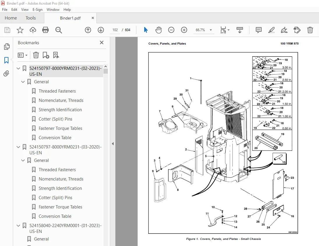
Covers, Panels, and Plates 204
Caster and Caster Wheels 204
Description 204
Caster, Replace 205
Caster Wheels, Replace 205
Painting Instructions 206
Label Replacement 206
524163981-1600YRM0691-(07-2002)-US-EN 213
toc 213
Power Steering 213
Safety Precautions Maintenance and Repair 214
General 217
EPS III 217
APS 217
Description 217
EPS III 217
APS System 218
Checks and Adjustments 218
General 218
Checks 218
Check Steering System for Correct Operation 218
Check Slow Travel Speed 219
Check High Lift Traction Shutoff 219
Dipswitches, EPS III 219
LED Indicators, EPS III 219
Checks, APS 220
Checks Prior to Powerup, APS 220
Dipswitches, APS 221
LED Indicators, APS 221
Adjustments 221
General 221
Steer Motor With Steering Chain Replacement, EPS III 221
Steer Motor With Steering Gear Replacement, APS 221
Return-to-Center Steering System 221
Command Potentiometer Adjustment, EPS III 221
Feedback Potentiometer Adjustment (Earlier Models Only) 223
Tach Generator Steering System, EPS III 226
Tach Generator Adjustment, EPS III 226
Sensitivity Adjustment, EPS III 226
Feedback Potentiometer Adjustment, EPS III 227
Slow Travel Adjustment, EPS III 227
Return-to-Center and Multiturn System, APS 228
Encoder Replacement, APS 228
Steering Chain Adjustment, EPS III 228
Repairs 229
RTC Steering System, EPS III 229
Command Potentiometer Replacement, EPS III 229
TGS System, EPS III 230
Tach Generator Replacement, EPS III 230
Feedback Potentiometer Replacement, EPS III 230
ECM Replacement, EPS III 230
Steer Motor Assembly and Steering Chain Replacement, EPS III 230
Typical Operating Voltages, EPS III 231
Steering Proximity Switch and Centering Proximity Switch, APS 232
Advanced Power Steering System Replacement 232
Troubleshooting 232
EPS III 232
APS 233
tables 213
Table 1 LED Indicators 219
Table 2 Sensitivity Adjustment 226
Table 3 Typical Operating Voltages 231
524163982-1800YRM0761-(06-2016)-US-EN 237
General 241
Description and Operation 241
Electric Brake Repair 242
Remove and Disassemble 242
Adjust (B801 and C826) 243
Assemble and Install (B801 and C826) 243
Adjust (C801 and D826) 244
Assemble and Install (C801 and D826) 245
Electric Brake Operational Check 245
Foot Switch Replacement 245
Remove 246
Repair 247
Install 247
Troubleshooting 248
524164049-2200YRM0933-(08-2008)-US-EN 251
toc 251
Electrical System 251
Safety Precautions Maintenance and Repair 252
Major Electrical System Features 257
Integrated System 257
CANbus Advantages 257
CANbus Communications 257
Electric Steering 257
Traction 257
Master Control Unit 257
Input Devices 257
Output Devices 258
Encoder Integrity 258
Test Encoders 258
Proximity Switches 258
Start Relay 258
Battery Discharge Indicator (BDI) 258
Multifunction Display 259
Setup 259
Setup Instructions 259
General Diagnostics 264
Power-On Self-Test 264
SEM Traction Motor Controller 265
Controller Removal 265
Install 266
Low-Voltage Protection Function 266
Checking Contactor Coils 266
Checking Transistor Controller 266
Component Repair and Testing 266
Troubleshooting 267
Fault Codes and Display Messages 268
Contactor and Electrical Panel Checks 281
Fuses 281
Contactors 281
General 281
Test 282
Tips 283
Disassemble and Assemble 283
Traction Throttle Sensor Removal and Installation 284
Instrument Panel Removal and Installation 286
Key Switch Removal and Installation 286
Remove 286
Install 286
Steering Indicator Gauge 286
Test 286
Remove and Install 286
Spy Glass Removal and Installation 287
Foot Switch Removal and Installation 287
Slack Chain Switch Removal and Installation 288
Limit Switch Removal and Installation 288
Drive and Hydraulic Pump Motors 289
Routine Preventive Maintenance 289
Preventive Maintenance Checks 290
Cleanliness 290
Connections 290
Discoloration and Burn Marks 290
Brushes 290
Short in Armature 290
Commutator 290
Bearings 290
Causes of Motor Failure 291
Overload 291
Shock Loading 291
Short in Field Coils 291
Short Brushes 291
High or Low Commutator Bar 291
Open Circuit 291
Low Battery Voltage 291
Eccentricity of Commutator 291
Overspeeding 291
Motor Tests 291
Excessive Current Draw 291
Measuring Current Draw 292
Excessive Resistance 292
Brush Springs 292
Drive Motor 292
Inspect 292
Preparation of Drive Motor Commutator 292
Fitting Motor Brushes (Motor Removed) 293
Drive Motor Brush and Brush Holder 294
Drive Motor Brush, Remove and Install (Motor Installed) 294
Drive Motor Brush Holder, Remove and Install (Motor Installed) 294
Drive Motor Disassembly and Assembly 295
Hoist Pump Motors 297
Maintenance Instructions 297
General Information 297
Brush Replacement 298
Hoist Motor 298
Remove and Install 298
Disassemble and Assemble 298
Height Encoder Troubleshooting 300
Description 300
Symptoms 300
Mast Proximity Switch Diagnostics 300
Height Encoder Diagnostics 300
Symptoms and Recommendations 300
Travel Speed Reduction 300
Additional Encoder Check 301
Steer Encoder Troubleshooting 301
Description 301
MDU Proximity Switch Issues 301
Steering System Issues 302
How to Check the Steer Encoder 302
tables 251
Table 1 Fault Codes and Display Messages 268
Table 2 Coil Resistance 282
524164050-2200YRM0956-(08-2008)-US-EN 305
toc 305
Electrical System 305
Safety Precautions Maintenance and Repair 306
Major Electrical System Features 311
Integrated System 311
CANbus Advantages 311
CANbus Communications 311
Electric Steering 311
Traction 311
Master Control Unit 311
Input Devices 311
Output Devices 312
Encoder Integrity 312
Test Encoders 312
Proximity Switches 312
Start Relay 312
Battery Discharge Indicator (BDI) 312
Multifunction Display 313
Setup 313
Setup Instructions 313
Control Valve Calibration Procedure 318
General Diagnostics 319
Power-On Self-Test 319
SEM Traction Motor Controller 319
Controller Removal 320
Install 320
Low-Voltage Protection Function 320
Checking Contactor Coils 321
Checking Transistor Controller 321
Component Repair and Testing 321
Troubleshooting 322
Fault Codes and Display Messages 323
Contactor and Electrical Panel Checks 336
Fuses 336
Contactors 336
General 336
Test 337
Tips 338
Disassemble and Assemble 338
Traction Throttle Sensor Removal and Installation 339
Instrument Panel Removal and Installation 341
Key Switch Removal and Installation 341
Remove 341
Install 341
Steering Indicator Gauge 341
Test 341
Remove and Install 341
Spy Glass Removal and Installation 342
Foot Switch Removal and Installation 342
Slack Chain Switch Removal and Installation 343
Limit Switch Removal and Installation 344
Drive and Hydraulic Pump Motors 344
Routine Preventive Maintenance 344
Preventive Maintenance Checks 345
Cleanliness 345
Connections 345
Discoloration and Burn Marks 345
Brushes 345
Short in Armature 345
Commutator 345
Bearings 345
Causes of Motor Failure 346
Overload 346
Shock Loading 346
Short in Field Coils 346
Short Brushes 346
High or Low Commutator Bar 346
Open Circuit 346
Low Battery Voltage 346
Eccentricity of Commutator 346
Overspeeding 346
Motor Tests 346
Excessive Current Draw 346
Measuring Current Draw 347
Excessive Resistance 347
Brush Springs 347
Drive Motor 347
Inspect 347
Preparation of Drive Motor Commutator 347
Fitting Motor Brushes (Motor Removed) 348
Drive Motor Brush and Brush Holder 349
Drive Motor Brush, Remove and Install (Motor Installed) 349
Drive Motor Brush Holder, Remove and Install (Motor Installed) 349
Drive Motor Disassembly and Assembly 350
Hoist Pump Motors 352
Maintenance Instructions 352
General Information 352
Brush Replacement 353
Hoist Motor 353
Remove and Install 353
Disassemble and Assemble 353
Height Encoder Troubleshooting 355
Description 355
Symptoms 355
Mast Proximity Switch Diagnostics 355
Height Encoder Diagnostics 355
Symptoms and Recommendations 355
Travel Speed Reduction 355
Additional Encoder Check 356
Steer Encoder Troubleshooting 356
Description 356
MDU Proximity Switch Issues 356
Steering System Issues 357
How to Check the Steer Encoder 357
tables 305
Table 1 Fault Codes and Display Messages 323
Table 2 Coil Resistance 337
524164051-2200YRM0957-(03-2011)-US-EN 361
toc 361
Wire Guidance 361
Safety Precautions Maintenance and Repair 362
General 365
Setup Instructions 366
Setup Mode 366
Setup Procedure 366
Align Steering 366
Multiturn Trucks Only 366
Self-Centering Trucks Only 366
Adjust the Drive Unit Centering Proximity Switch 366
Calibrate Guidance Control System 366
Check Operation of System 367
Troubleshooting 367
Check Guide Wire 367
Is Guidance Option Enabled? 367
Check Software Configuration 367
Check Sensors 368
Check Control Cable 368
Check Steering System 368
Check Steering Drive Components 368
Chain Steer Trucks 368
Gear Steer Trucks 368
Check Drive Unit Bearings 368
Guidance Switch Replacement 368
Sensors Replacement 369
524164052-4000YRM0763-(01-2012)-US-EN 375
toc 375
MAST 375
Safety Precautions Maintenance and Repair 376
General 379
Mast Weldments 379
Operator Platform 381
Two-Stage Mast 382
Description 382
Load Rollers 384
Operation 384
Three-Stage Mast 384
Description 384
Operation 385
524164053-4000YRM0764-(05-2018)-US-EN 389
General 393
Forks 393
Replace 393
Safety Procedures When Working Near Mast 395
Operator Platform 397
Remove 397
Install 399
Two-Stage Mast 400
Remove 400
Disassemble 400
Clean and Inspect 402
Lift Cylinders 404
Assemble 404
Install 404
Three-Stage Mast 408
Remove 408
Disassemble 408
Clean and Inspect 410
Lift Cylinders 410
Assemble 410
Install 411
Load Wheels Replacement 411
Lift System Leak Check 412
Lift Chain Adjustment 412
Mast Adjustments 413
Operator Platform Adjustment 414
Troubleshooting 415
524164054-8000YRM0922-(01-2019)-US-EN 419
Battery Specifications 423
Lubrication Specifications 423
Master Drive Unit Specifications 424
System Wire Guidance Specifications 424
Hydraulic System 425
Torque Specifications 426
Master Drive Unit, Chain-Steered 426
Master Drive Unit, Gear-Steered 426
Steering System 426
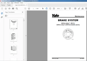
Brake System 426
Hydraulic System 426
OS/SS030BE 426
OS030EC 427
Mast 427
Torque Specifications 427
Master Drive Unit (Early Production) 427
Master Drive Unit (Late Production) 427
Traction Motor 427
Steering System 427
Hydraulic System 427
OS030EF 427
(FS/OS/SS030BF) 428
Load Wheels (OS030EF and OS030BF) 428
Stability Caster (FS030BF) 428
MAST 428
Platform 428
Wire Guidance 428
Electrical Components 429
524164055-8000YRM0923-(10-2006)-US-EN 433
toc 433
Diagrams 433
Safety Precautions Maintenance and Repair 434
524164056-8000YRM0958-(02-2007)-US-EN 449
toc 449
Diagrams 449
Safety Precautions Maintenance and Repair 450
524164057-8000YRM0924-(12-2009)-US-EN 467
toc 467
Periodic Maintenance 467
Safety Precautions Maintenance and Repair 468
General 471
How to Move a Disabled Truck 471
How to Tow the Lift Truck 471
How to Put a Lift Truck on Blocks 472
How to Raise the Drive Tire 472
How to Raise the Load Wheels 473
Maintenance Schedule 474
Maintenance Procedures Every 8 Hours or Daily 477
How to Make Checks With Key Switch in the OFF Position 477
Hydraulic System 477
Battery 478
Mast, Platform, Forks, Lift Chains, and Header Hoses 478
Tether Line and Belt 480
Pallet Clamp 480
Tire, Wheels, and Caster 480
How to Make Checks With Key Switch in the ON Position 480
Gauges, Lights, Horn, and Fuses 480
Fuses 481
Switches and Direction/Speed Control 481
Lift System Operation 482
Brake 483
Steering System 483
Maintenance Procedures Every 350 Hours or 2 Months 483
Brake 483
Electrical Cable Sheaves 483
Hydraulics 483
Hydraulic Hoses 483
Hydraulic Tank Breather 483
Electrical Inspection 484
Contactors 484
Motor Brushes 484
Safety Labels 485
Mast 485
Check for Leaks in Lift System 486
Check Lift Cylinders for Leaks 486
Master Drive Unit 486
Lift Chains 486
Maintenance Procedures Every 2000 Hours or Yearly 488
Master Drive Unit 488
Changing the Oil 488
Traction Motor and Input Pinion Splines 488
Steering Chain 488
Wheels and Bearings 488
How to Change Hydraulic Oil and Filter 488
Battery Maintenance 489
How to Charge Battery 489
How to Change the Battery 490
General 490
Battery, Remove 490
Battery, Install 491
Wheels and Tires 492
How to Change Drive and Steer Tires 492
How to Replace Load Wheels 493
tables 467
Table 1 Maintenance Schedule 474
Table 2 Fuses 481
Table 3 Motor Brush Minimum Dimensions 484
Table 4 Battery Specifications 492
524166249-0630YRM1021-(03-2021)-US-EN 497
HFK400 Master Drive Unit 501
General 501
Description 501
Drive Unit Maintenance and Repair 501
Remove 501
Install 503
Disassemble 503
Assemble 508
Troubleshooting 516
GK Master Drive Unit 517
General 517
Description 517
Maintenance 518
Changing the Oil 518
Traction Motor and Drive Unit Splines 518
Remove 518
Assemble 519
Mounting Electric Motor 519
Pivoted Connection – Geared Steering 520
Disassemble 520
Install 520
Troubleshooting 521
S.V 05/24