Yale Forklift E216 (ERP20ALF, ERP25ALF, ERP30ALF, ERP32ALF Europe) Service Manual PDF
$34.95
Yale Forklift E216 (ERP20ALF, ERP25ALF, ERP30ALF, ERP32ALF Europe) Service Manual – PDF DOWNLOAD
Description
Yale Forklift E216 (ERP20ALF, ERP25ALF, ERP30ALF, ERP32ALF Europe) Service Manual – PDF DOWNLOAD
FILE DETAILS:
Yale Forklift E216 (ERP20ALF, ERP25ALF, ERP30ALF, ERP32ALF Europe) Service Manual – PDF DOWNLOAD
Language : English
Pages : 992
Downloadable : Yes
File Type : PDF
IMAGES PREVIEW OF THE MANUAL:
TABLE OF CONTENTS:
Yale Forklift E216 (ERP20ALF, ERP25ALF, ERP30ALF, ERP32ALF Europe) Service Manual – PDF DOWNLOAD
AC MOTOR CONTROLLERS – DISPLAY PANEL 1
toc 1
AC Motor Controllers/Display Panel 1
Safety Precautions Maintenance and Repair 2
Description 5
General 5
AC Motors 5
Motor Controllers 5
Master Controller 5
Dash Display 5
Controller Area Network Bus (CANbus) 5
Master Controller Checks and Adjustments 6
Function Settings 7
General 7
Function Numbers 7
Function Descriptions 10
General 10
Function Number 1 BATTERY VOLTAGE 10
Function Number 2 EXTENDED SHIFT 10
Function Number 3 ACCELERATION 1 10
Function Number 4 ACCELERATION 2 10
Function Number 5 TOP SPEED LIMIT 10
Function Number 6 REGEN BRAKING 10
Function Number 7 AUTO DECELERATION 11
Function Number 8 BDI ADJUSTMENT 11
Function Number 9 LIFT INTERRUPT 11
Function Number 10 POWER STEERING TIME DELAY 11
Function Number 11 SERVICE REMINDER 11
Function Number 12 CUSTOM 11
Function Number 13 PUMP SPEED 1 11
Function Number 14 PUMP SPEED 2 12
Function Number 15 PUMP SPEED 3 12
Function Number 16 PUMP ACCELERATION 12
Troubleshooting 12
General 12
Controller Status Light Emitting Diodes (LEDs) 13
Master Controller 13
AC Motor Controllers 13
Status Codes 19
AC Motor Controllers Status Code Charts 21
Troubleshooting When Dash and/or Lift Truck is not Operational 42
Typical Symptoms 42
Truck Runs but Dash Display is not Operational, or Only Displays 42
Truck Does Not Run and Dash is Not Operational or Only Displays 43
Hydraulics Operate Normally, Traction Does Not Operate Correctly 44
Traction Operates Normally, Hydraulics do Not Operate Correctly, 44
AC Transistor Motor Controller Replacement 44
General 44
General Maintenance Instructions 50
Special Precautions 50
Fuses 51
Fan Test 51
Contactors 51
Repair 51
Thermal Sensors 55
Motor Controller, Replace 55
Display Panel 56
General 56
Premium Display Panel 56
Standard Display Panel 56
Display Functions and Features 57
Key-On Initialization 57
Standard Display 58
Premium Display 58
Lift Truck Inspection Function 59
Access to Service Functions 59
Service Functions 59
Service Functions 60
Performance Modes 62
Battery Discharge Indicator (BDI) 62
Hourmeter 63
Dash Display Service Menu Navigation 69
General 69
Moving Through Menu Selections 69
Editing and Adding Information 69
tables 1
Table 1 Factory Parameters for ERP20-30ALF (ERP040-060DH) (D216 7
Table 2 Factory Setting for ERC020-032AGF (ERC40-65GH) (A908) 8
Table 3 Factory Setting for ERC/P16-20AAF (ERC030-040AH) (B814/ 8
Table 4 Factory Parameters for ERC35-55HG (ERC70-120HH) (B839/C 9
Table 5 List of Status Codes 19
Table 6 42-Pin Connections/Descriptions for Master Controller 52
Table 7 Pin Connections/Descriptions for 72/80 (Gen IV) Volt Mo 54
Table 8 Pin Connections/Descriptions for 36/48 and 72v/80v (Gen 54
AC MOTOR MAINTENANCE 73
toc 73
AC Motor Repair 73
Safety Precautions Maintenance and Repair 74
General 77
AC Motor Repair 78
Disassemble 78
Assemble 80
Drive End Bearing, Replace 81
Disassemble, ERP20-32ALF (ERP040-065DH) (E216) Traction Motor 81
Assemble, ERP20-32ALF (ERP040-065DH) (E216) Traction Motor 83
Troubleshooting 84
BRAKE PEDAL AND LINKAGE 87
toc 87
Brake Pedal and Linkage 87
Safety Precautions Maintenance and Repair 88
General 91
Brake Pedal Replacement 91
Remove 91
Clean 91
Inspect 91
Install 91
Master Cylinder Repair 93
Remove 93
Disassemble 93
Clean 93
Inspect 93
Assemble 93
Install and Adjust 93
Parking Brake Replacement 96
Remove 96
Clean 97
Inspect 97
Install 97
Adjust 98
Brake Pedal Adjustment 98
Master Cylinder Adjustment 100
Brake System Air Removal 100
Using Power Pressure Bleed System 100
Using Brake Pedal Bleed System 101
CAPACITIES AND SPECIFICATIONS 107
toc 107
Capacities and Specifications 107
Safety Precautions Maintenance and Repair 108
Counterweight 111
Hydraulic System 111
Steering System 112
Wheels and Tires 112
Battery Specifications 113
Capacities 113
Movement Rates (Maximum) for Tilt Cylinders 114
Mast Speeds 114
Mast Speeds – ERP20-32ALF (72 or 80 Volt) Europe 114
Mast Speeds – ERP040-065DH (72 or 80 Volt) Americas 115
Torque Specifications 117
Frame 117
Drive Axle, Speed Reducer, and Differential 117
Masts 117
E-Hydraulic Control Valve 117
Adhesives and Sealants 118
tables 107
Table 1 Manual Control Valve 111
Table 2 E-Hydraulic Control Valve 111
CYLINDER REPAIR 121
DC MOTOR MAINTENANCE 169
General 173
Brush and Commutator Inspection 174
Hydraulic Pump Motor and Traction Motor 174
Steering Pump Motor 177
Normal Commutator Surface 177
Commutator Problems 177
Brush Replacement 182
Stoning the Commutator 185
Motors Repair 186
Disassemble 187
Traction Motor and Hydraulic Pump Motor 187
Steering Pump Motor 188
Assemble 192
Traction Motor and Hydraulic Pump Motor 192
Steering Pump Motor 194
Brush Alignment, Traction and Hydraulic Motors 196
Tests for Damaged Field and Armature 197
Test for an Open Circuit in One Armature Winding 197
Test for Short Circuit in One Armature Winding 197
Test for Short Circuit to Armature Shaft 198
Test for Open Circuit in Field Coil 198
Test for Short Circuit in Field Coil 199
Test for Short Circuit Between Field and Motor Case 199
Brush Holder Test 199
Troubleshooting 200
DIAGRAM 205
toc 205
Electrical Diagrams 205
Safety Precautions Maintenance and Repair 206
DRIVE AXLE WET BRAKE 239
toc 239
Drive Unit Assembly 239
Safety Precautions Maintenance and Repair 240
General 243
Description 243
Wet Disc Brake Repair 247
Wet Disc Brakes 247
Remove 247
Inspect 251
Install 251
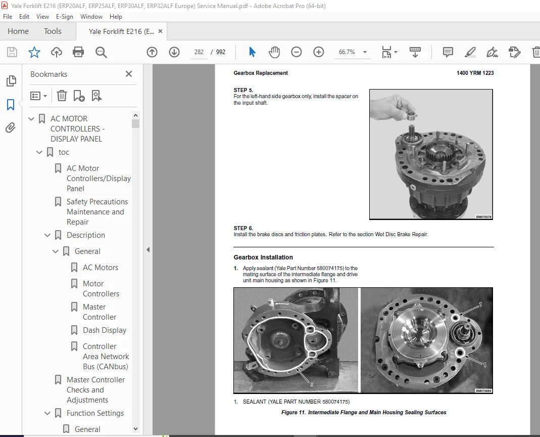
Gearbox Replacement 256
Remove 256
Gearbox Removal 256
Intermediate Flange Removal 257
Disassemble 259
Intermediate Flange 259
Assemble 267
Intermediate Flange 267
Install 280
Intermediate Flange Installation 280
Gearbox Installation 282
Drive Unit Removal 284
Main Housing Repair 288
Main Housing, Right-Hand Side 288
Remove 288
Disassemble 289
Clean and Inspect 290
Assemble 291
Install 291
Main Housing, Left-Hand Side 292
Remove 292
Disassemble 293
Clean and Inspect 294
Assemble 294
Install 294
Differential Assembly Replacement 295
Remove 295
Install 295
Traction Motor Repair 296
Remove 296
Disassemble 296
Assemble 299
Install 299
Drive Unit Installation 300
Torque Specifications 301
Troubleshooting 302
ELECTRICAL SYSTEM (TRUCKS WITH AC CONTROLLERS) 305
toc 305
Electrical System (Trucks With AC Controllers) 305
Safety Precautions Maintenance and Repair 306
General 309
Description 310
Features of the Display Panels 310
Other Control Components 311
Display Panel and Key Switch Replacement 312
Display Panel, Replace 312
Key Switch, Replace 314
Controller Replacement 314
Traction and Pump Motor Controller Replacement 314
Master Controller, Replace 320
Master Controller, Remove ERP20-30ALF (ERP040-060DH) (D216), ERP 320
Master Controller, Install ERP20-30ALF (ERP040-060DH) (D216), ER 320
Master Controller, Remove ERC/P16-20AAF (ERC030-040AH) (B814/C81 322
Master Controller, Install ERC/P16-20AAF (ERC030-040AH) (B814/C8 322
Master Controller, Remove ERC35-55HG (ERC070-120HH) (B839/C839) 324
Master Controller, Install ERC35-55HG (ERC070-120HH) (B839/C839) 324
Control Components Replacement 325
General 325
Start Switch, Replace 325
Brake Light Switch, Replace 326
Seat Switch, Replace 326
Parking Brake Switch, Replace 327
Foot Directional Control Pedal Direction Switches, Replace 329
Steering Column Direction Control Switches, Replace 332
Remove 332
Install 332
Brake Fluid Switch, Replace 334
Brush Wear and Over Temperature Sensors (DC Pump Motor Only) 334
Rocker Switches for Lights, Replace 334
Accelerator Position Sensor, Replace 335
On-Demand Steering Sensor, Replace 336
Lights, Converter, Relay, and Reverse Alarm 336
Brake, Tail, and Reverse Light Assembly, Replace 337
Incandescent Assembly 337
LED Assembly – Remove 339
LED Assembly – Install 339
Strobe Light Assembly, Replace 342
Wire Harness Repair 343
Del-City Crimp-Solder-Shrink Splice 343
Front, Rear Driving Light or Spot Light Assemblies, Replace 344
Converter, Replace 344
Remove, Lift Truck Models ERP20-30ALF (ERP040-060DH) (D216), ERP 344
Install, Lift Truck Models ERP20-30ALF (ERP040-060DH) (D216), ER 346
Remove, Lift Truck Models ERC20-32AGF (ERC040-065GH) (A908) and 346
Install, Lift Truck Models ERC20-32AGF (ERC040-065GH) (A908) and 346
Remove, Lift Truck Models ERC35-55HG (ERC70-120HH) (B839/C839) 348
Install, Lift Truck Models ERC35-55HG (ERC70-120HH) (B839/C839) 348
Reverse Relay, Replace 349
Lift Truck Models ERC20-32AGF (ERC040-065GH) (A908), ERC/P16-20A 349
Lift Truck Models ERC35-55HG (ERC70-120HH) (B839/C839) 349
Backup Alarm, Replace 351
Horn and Horn Button, Replace 351
Horn Replacement for Lift Trucks ERP20-30ALF (ERP040-060DH) (D21 351
Horn Replacement for Lift Trucks ERC35-55HG (ERC70-120HH) (B839/ 353
Horn Switch and Cover, Replace 354
Hydraulic Pump Switches 355
Fan Power Supply, Replace 355
Remove, Lift Truck Models ERC35-55HG (ERC70-120HH) (B839/C839) 355
Install, Lift Truck Models ERC35-55HG (ERC70-120HH) (B839/C839) 355
Remove, Lift Truck Models ERP20-30ALF (ERP040-060DH) (D216) and 356
Install, Lift Truck Models ERP20-30ALF (ERP040-060DH) (D216) and 357
Remove, Lift Truck Models ERC20-32AGF (ERC040-065GH) (A908) 357
Install, Lift Truck Models ERC20-32AGF (ERC040-065GH) (A908) 357
Control and Power Fuse Check 358
Fuse Locations 358
Brake Light Switch Adjustment 364
Seat Switch Check 365
Seat Brake Adjustment 365
Parking Brake Switch Adjustment 366
Direction Switches Check 366
Foot Directional Control Pedal 366
Steering Column 367
Foot Directional Control Pedal or Accelerator Pedal Adjustment 367
Accelerator Position Sensor Adjustment and Start Switch Adjustme 368
Acceleration Position Sensor, Adjust 368
Start Switch, Adjust 370
tables 305
Table 1 Wire Splice Size 343
ELECTRO-HYDRAULIC CONTROL VALVE 373
toc 373
Electro-hydraulic Control Valve 373
Safety Precautions Maintenance and Repair 374
General 377
Description 377
Electro-Hydraulic Control System 377
Electro-Hydraulic Control Valve 380
Electro-Hydraulic Valve Driver Module 396
Mini-Lever Module (MLM) 396
Joystick 397
Electro-Hydraulic Control Valve Repair 398
Remove 398
Disassemble 407
Solenoid Coil Replacement 409
Cartridge Replacement 411
Electro-Hydraulic Pressure Reducing Valve (EHPR) Replacement 412
Lift Circuit Check Valve Replacement 413
Compensator Cartridge Replacement 413
Primary and Secondary Relief Valves Replacement 413
Tilt Counterbalance Valve Replacement 414
Flow Regulator Valve Replacement 414
Assemble 414
Install 414
E-Hydraulics Calibration 423
Mini-Lever Module 425
Mini-Lever Module (MLM) 425
Remove 425
Install 425
Mini-Lever Replacement 425
Remove 425
Clean and Inspect 426
Install 426
Push Button Switch Replacement 427
Remove 427
Install 428
Test 429
Mini-levers 429
Full Stroke Test 429
Function Returns to Neutral Test 429
Push Button Switch 430
Joystick 430
Remove and Disassemble 430
Inspect 430
Assemble and Install 430
Troubleshooting 431
tables 373
Table 1 Primary and Secondary Relief Valve Values 383
Table 2 Solenoid Resistance Values 409
Table 3 Cartridge and Solenoid Coil Nut Torque for Lift truck M 412
Table 4 Cartridge and Solenoid Coil Nut Torque for Lift truck M 412
FRAME 443
toc 443
Frame 443
Safety Precautions Maintenance and Repair 444
General 447
Description 447
Main Frame 447
Other Frame Weldments 447
Overhead Guard 447
Battery Restraint, Hood, and Seat Assembly 451
Hood With Manual Hydraulic Levers 452
Hood With E-Hydraulics 453
Operator Restraint System and Seat Assembly 454
Operator Restraint System 454
Emergency Locking Retractor (ELR) 454
Hood and Seat Latches 455
Overhead Guard Replacement 455
Remove 455
Install 455
Hood, Seat Assembly, and Operator Restraint Replacement 457
Hood and Seat Assembly 457
Remove 457
Install 459
Counterweight Replacement 463
Remove 463
Install 463
Hydraulic Tank Replacement 464
Remove 464
Inspect 464
Clean 465
Steam Method 465
Chemical Solution Method 465
Additional Preparations for Tank Repair 466
Small Leaks, Repair 466
Large Leaks, Repair 466
Preparations for Usage After Repair 466
Install 466
Painting Instructions 467
Safety Label Replacement 469
Battery Specifications 471
ERP20-32ALF (ERP040-065DH) (E216) Model Trucks 471
tables 443
Table 1 Counterweights 463
HYDRAULIC SYSTEM 475
toc 475
Hydraulic System 475
Safety Precautions Maintenance and Repair 476
General 479
Description 479
Hydraulic System 479
Operation 487
Hydraulic System 487
Hydraulic Gear Pump 493
Steering Pump 493
Hydraulic Tank Repair 501
Tank, Remove [ERC/P16-20AAF (ERC030-040AF, AG/BG) (A814); ERC/P1 501
Tank, Remove [ERP20-30ALF (B216) and ERP20-30ALF (ERP040-060DH) 503
Tank, Remove [ERP20-32ALF (ERP040-065DH) (E216)] 504
Hydraulic Tank [ERC35-55HG (ERC70-120HH) (B839/C839)] 504
Inspect 505
Small Leaks, Repair 506
Large Leaks, Repair 506
Clean 506
Steam Method 506
Chemical Solution Method 507
Additional Methods for Tank Repair 507
Tank, Install [ERC/P16-20AAF (ERC030-040AF, AG/BG) (A814); ERC/P 507
Tank, Install [ERP20-30ALF (B216) and ERP20-30ALF (ERP040-060DH) 508
Tank, Install [ERP20-32ALF (ERP040-065DH) (E216)] 508
Filter Replacement 509
All Lift Trucks Except [ERC35-55HG (ERC70-120HH) (B839/C839); ER 509
Remove 509
Install 510
Lift Truck Models [ERC35-55HG (ERC70-120HH) (B839/C839)] 510
Remove 510
Install 510
Lift truck Models [ERC20-32AGF (ERC040-065GH) (A908) and ERC/P16 511
Remove 511
Install 511
Lift Truck Models [ERP20-32ALF (ERP040-065DH) (E216)] 513
Remove 513
Install 513
Hydraulic Pump Repair 516
Hydraulic Pump, Remove [ERC/P16-20AAF (ERC030-040AF, AG/BG) (A81 516
Hydraulic Pump, Disassemble ERC/P16-20AAF (ERC030-040AF, AG/BG) 516
Inspect 518
Clean 518
Pump Seal Replace and Pump Assemble 518
Assemble Pump on Motor 518
Hydraulic Pump and Motor, Install [ERC/P16-20AAF (ERC030-040AF, 520
Hydraulic Pump, Remove [ERP20-30ALF (B216); ERP20-30ALF (ERP040- 521
Hydraulic Pump, Disassemble [ERC35-55HG (ERC70-120HH) (B839/C839 522
Hydraulic Pump, Inspect [ERC35-55HG (ERC70-120HH) (B839/C839) an 524
Hydraulic Pump, Clean [ERC35-55HG (ERC70-120HH) (B839/C839) and 524
Hydraulic Pump, Assemble [ERC35-55HG (ERC70-120HH) (B839/C839) a 524
Hydraulic Pump and Motor, Install [ERP20-30ALF (B216); ERP20-30A 524
Main Control Valve Repair 526
Steering Pump Repair 526
Pump, Remove and Disassemble [ERC/P16-20AAF (ERC030-040AF, ERC03 526
Pump, Remove and Disassemble [ERP20-30ALF (B216); ERP20-30ALF (E 528
Pump, Assemble and Install 530
Steering Control Unit Replacement 531
Remove 531
Install 531
Steering Cylinder Repair 537
Main Control Valve Check and Adjust 537
Steering Relief Valve Check and Adjust 538
Specifications 538
Relief Valve Pressures* 538
Hydraulic Tank Capacity (dipstick full mark) 539
Hydraulic Pump Capacities – All Models Except ERC35-55HG (ERC70- 539
Hydraulic Pump Capacities – Models ERC35-55HG (ERC70-120HH) (B83 539
Troubleshooting 539
Steering 539
Steering Housing and Steering Control Unit 540
Hydraulic System 541
INDUSTRIAL BATTERY 547
General 551
Battery Type 551
Lead-Acid Batteries 551
Lithium-Ion Batteries 552
Specific Gravity 552
Chemical Reaction in a Cell 552
Electrical Terms 554
Battery Selection 555
Battery Voltage 556
Battery as a Counterweight 556
Battery Ratings 556
Kilowatt-Hours 557
Battery Maintenance 557
Safety Procedures 557
Maintenance Records 558
New Battery 558
Cleaning Battery 558
Adding Water to Battery 560
Hydrometer 561
Battery Temperature 561
Charging Battery 562
Types of Battery Charges 563
Methods of Charging 564
Troubleshooting Charger 565
Knowing When Battery Is Fully Charged 565
Where to Charge Batteries 565
Equipment Needed 565
Battery Connectors 566
Battery Care 566
Troubleshooting 568
MAIN CONTROL VALVE 573
toc 573
Manual hydraulic Control Valve 573
Safety Precautions Maintenance and Repair 574
General 577
Description 577
Operation 580
ERC/P16-20AAF (ERC030-040AF, AG/BG) (A814); ERC/P16-20AAF (ERC03 580
ERP20-30ALF (B216), ERP20-30ALF (ERP040-060DH) (D216) and ERP20- 580
Lift Section 582
Tilt Section 582
Tilt Backward 582
Tilt Forward 582
Relief Valve 584
Main Control Valve Repair 585
Main Control Valve Without OPS Solenoid 585
Remove 585
Disassemble 585
Clean and Inspect 589
Assemble 589
Install [ERC/P16-20AAF (ERC030-040AF, AG/BG) (A814); ERC/P16-20A 590
Install [ERP20-30ALF (B216), ERP20-30ALF (ERP040-060DH) (D216) a 590
Main Control Valve With OPS Solenoid 591
Remove 591
Disassemble 591
Clean and Inspect 593
Relief Valve Repair 595
Assemble 596
Install 597
Control Lever Linkage Repair 597
Remove [ERC/P16-20AAF (ERC030-040AF, AG/BG) (A814),ERC/P16-20AAF 597
Disassemble [ERC/P16-20AAF (ERC030-040AF, AG/BG) (A814),ERC/P16- 597
Assemble and Install [ERC/P16-20AAF (ERC030-040AF, AG/BG) (A814) 599
Control Valve Linkage Repair 599
Remove and Disassemble [ERC/P16-20AAF (ERC030-040AF, AG/BG) (A81 599
Assemble and Install [ERC/P16-20AAF (ERC030-040AF, AG/BG) (A814) 600
Control Lever Linkage Repair 600
Remove [ERP20-30ALF (B216), ERP20-30ALF (ERP040-060DH) (D216) an 600
Disassemble [ERP20-30ALF (B216), ERP20-30ALF (ERP040-060DH) (D21 602
Assemble and Install [ERP20-30ALF (B216), ERP20-30ALF (ERP040-06 602
Pressure Relief Valve Check and Adjustment 603
Primary Relief Valve 603
Secondary Relief Valve 604
Troubleshooting 605
MAST REPAIRS 609
General 613
Safety Procedures When Working Near Mast 614
Fork Replacement 616
Remove, Lift Trucks Not Equipped With Fork Positioner Or Equipped With Fork Positioner Before August, 2012 616
Remove, Lift Trucks Manufactured After August, 2012 And Equipped With Fork Positioner 618
Install, Lift Trucks Not Equipped With Fork Positioner Or Equipped With Fork Positioner Before August, 2012 619
Install, Lift Trucks Manufactured After August, 2012 And Equipped With Fork Positioner 619
Checks, Lift Trucks Not Equipped With Fork Positioner Or Equipped With Fork Positioner Before August, 2012 620
Checks, Lift Trucks Manufactured After August, 2012 And Equipped With Fork Positioner 621
Carriages Repair 622
Standard Carriage 622
Remove 622
Repair 623
Install 623
Standard Carriage, Remove 624
Hang-On Sideshift Carriage, Remove 625
Standard Carriage and Hang-On Sideshift Carriage, Repair 626
Standard Carriage, Install 627
Hang-On Sideshift Carriage, Install 627
Integral Sideshift Carriage 628
Remove 628
Clean and Inspect 631
Repair 632
Install 632
Fork Positioner 633
Remove 633
Clean and Inspect 638
Disassemble and Assemble 638
Install 638
Fork Positioner Hydraulic Hose Adjustment 639
Disconnecting Attachment Hydraulic Quick Disconnect Hoses 641
Connecting Attachment Hydraulic Quick Disconnect Hoses 641
Mast Repair 642
Mast, Remove 642
Two-Stage LFL and Two-Stage FFL Masts 645
Disassemble 645
Clean and Inspect 655
Three-Stage FFL Mast 656
Disassemble 656
Clean and Inspect 664
Two-Stage LFL and Two-Stage FFL Mast 666
Assemble 666
Three-Stage FFL Mast 669
Assemble 669
Four-Stage FFL Mast – Manufactured Before July, 2009 671
Disassemble 671
Clean and Inspect 676
Assemble 678
Four-Stage FFL Mast – Manufactured After July, 2009 679
Disassemble 679
Clean and Inspect 686
Assemble 689
Mast, Install 690
Header Hose Arrangement 693
Two-Stage LFL 693
Two-Stage FFL 701
Three-Stage FFL 716
Standard 716
Optional Equipment Lift Truck GLP/GDP20-35VX (GP/GLP/GDP040-070VX) (B875) 733
Four-Stage FFL Mast – Manufactured Before July, 2009 741
Four-Stage FFL Mast – Manufactured After July, 2009 750
Adjustment 757
Lift Chains Adjustment 757
Carriage Adjustments 760
Mast Adjustments 760
Load Roller Adjustment 760
Mast Side Kicking Adjustment 763
MAST-DESCRIPTION 767
toc 767
Mast 767
Safety Precautions Maintenance and Repair 768
General 771
Description and Operation 771
Carriages 771
Mast Mounts 773
Two-Stage Mast, Limited Free-Lift (LFL) 774
Description and Operation 774
Two-Stage Mast, Full Free-Lift (FFL) 776
Description and Operation 776
Three-Stage Mast, Full Free-Lift (FFL) 778
Description and Operation 778
Four-Stage Mast 780
Description and Operation 780
Cylinder Cushion During Lifting Sequence 784
Cylinder Cushion During Lowering Sequence 785
METRIC AND INCH (SAE) FASTENERS 789
General 793
Threaded Fasteners 793
Nomenclature, Threads 793
Strength Identification 794
Cotter (Split) Pins 795
Fastener Torque Tables 800
Conversion Table 802
PERIODIC MAINTENANCE 811
toc 811
Periodic Maintenance 811
Safety Precautions Maintenance and Repair 812
General 817
Serial Number Data 817
How to Move A Disabled Lift Truck 817
How to Tow a Lift Truck 817
How to Put Lift Truck on Blocks 818
How to Raise Drive Tires 818
How to Raise Steering Tires 819
Maintenance Schedule 819
Maintenance Procedures Every Shift 823
How to Make Checks With Key Switch OFF 823
Tires and Wheels 823
Forks 824
Inspect 824
Mast, Carriage, Header Hoses, and Lift Chains, Inspect 825
Safety Labels 826
Steering Column Latch 826
Operator Restraint System 826
Emergency Locking Retractor (ELR) 826
Seat Rails 827
Battery Restraint System 827
Battery 828
Hydraulic System 829
How to Make Checks With Key Switch ON 829
Emergency Stop Knob 829
Horn, Lights, and Alarm 830
Steering System 830
Service Brakes 830
Parking Brake 830
Hydraulic Control Levers 831
Direction and Speed Control Pedals 831
Lift System Operation 831
Oil Leaks 831
Seat Switch 831
First Service After First 100 Hours of Operation 832
Steer Wheel Nut Torque 832
Change Filter for Hydraulic Oil 832
Remove 832
Install 832
Electrical Inspection 834
AC Hydraulic Pump Motor 834
Contactors 836
Mast 836
Forks 837
Lift Chains 838
Wear Check 838
Lift Chain Lubrication 839
Maintenance Procedures Every 1000 Hours or 6 Months 839
Wheel Nut Torque 839
Header Hose Checks 839
Mast 839
Lift Chains 841
Wear Check 841
Lift Chain Lubrication 842
Forks 842
Check Upper and Lower Bearings, Integral Sideshift Carriage 842
Steering Tie Rods 842
Steering Axle Spindles 842
King Pins 842
Gearbox and Brake Chamber 843
Brake Oil 844
Parking Brake Adjustment 844
Electrical Inspection 845
AC Hydraulic Pump Motor 845
Contactors 847
Other Lubrication 847
Maintenance Procedures Every 2000 Hours or Yearly 847
Change Filter for Hydraulic Oil 847
Remove 847
Install 847
Change Hydraulic Oil 849
Hydraulic Tank Breather 849
Remove 849
Install 849
Gearbox and Brake Oil Replacement 850
Remove 850
Install 850
Brake Oil Replacement 851
Wheel Bearings 851
Steer Wheels, Lubrication 851
Lift Chains 851
Forks 851
Replace Upper and Lower Bearings, Integral Sideshift Carriage 852
Other Lubrication 852
Battery Maintenance 852
How to Charge Battery 852
How to Change Battery 853
General 853
Lift and System Leak Check 855
Lift Cylinders Leak Check 855
Tilt Cylinders Leak Check 856
Safety Procedures When Working Near Mast 856
WHEN WORKING NEAR THE MAST ALWAYS: 856
Lift Chain Adjustment 858
Welding Repairs 859
Overhead Guard Changes 860
Wheels and Tire Maintenance 860
Pneumatic Tires and Wheels 860
Remove Wheels From Lift Truck 860
Remove Wheel From Pneumatic Tire 861
Install Three- or Four-Piece Wheel in Pneumatic Tire 862
Add Air to Tires 863
Wheels, Install 863
Solid Rubber Tires on Pneumatic Wheels 864
Remove Wheels From Lift Truck 864
Remove Solid Rubber Tire From Pneumatic Wheel 864
Install Solid Rubber Tire on Pneumatic Wheel 866
Wheels, Install 867
Snap-On Tire, Change 867
Remove Snap-On Solid Tire From Wheel 868
Install Snap-On Solid Tire on Wheel 869
Adhesives and Sealants 870
tables 811
Table 1 Maintenance Schedule 819
STEERING HOUSING AND CONTROL UNIT (LATER MODELS) 873
toc 873
Steering Housing and Control Unit 873
Safety Precautions Maintenance and Repair 874
General 877
Description 877
Operation 878
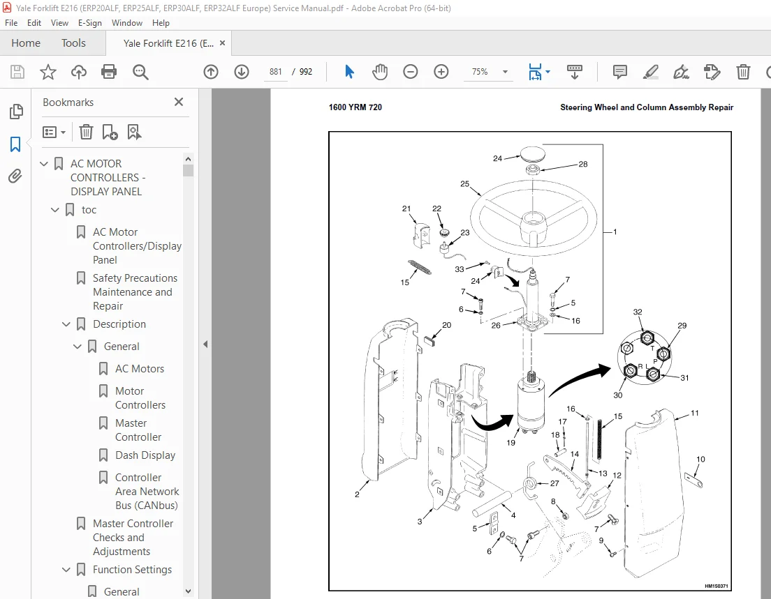
Steering Wheel and Column Assembly Repair 879
Assembly Components, Remove 879
Steering Control Unit, Disassemble 884
Steering Control Unit, Clean 884
Steering Control Unit, Assemble 884
Assembly Components, Install 886
System Air Removal 888
Troubleshooting 888
STEERING SYSTEM 893
toc 893
Steering System for AC Electric Lift Trucks 893
Safety Precautions Maintenance and Repair 894
General 897
Description 898
Steering Wheel and Column Assembly Repair 899
General 899
Assembly Components, Remove 901
Assembly Components, Install 902
Power Steering Motor and Pump 903
Description 903
Remove 903
Disassemble 906
Install 906
Power Steering Pump, Repair 906
Seal, Replace 907
Steering System Air Removal 908
Steering Pressure Check 908
Steering Motor Circuits Check 909
Troubleshooting 910
TROUBLESHOOTING AND ADJUSTMENTS WITH A COMPUTER W AC CONTROLLER 915
toc 915
Troubleshooting and Adjustments Using the AC Controls Program (E 915
Safety Precautions Maintenance and Repair 916
General 919
Computer Requirements 919
Software, Install 919
Language Selection 919
Demo Mode 920
Connect PC to Lift Truck 924
Starting AC Controls Program 926
Lift Truck Control Setup 931
Change Lift Truck Serial Number or Hourmeter 931
Setting Factory Default Values or Changing Lift Truck Parameters 932
Create New Custom Lift Truck Configuration 938
Lift Truck Configuration Properties 941
Import New Lift Truck Configuration From Disk 944
Delete Custom Lift Truck Configuration or Password File 946
Dash Display 949
Custom Display Languages 949
Download Display Language 951
Clear Operator Log 951
Password Functions 954
Enable/Disable Password and Lift Truck Inspection Functions 954
Truck Inspection Checklist 954
Password 954
Password Properties 954
Create New Password File 959
Download Passwords 960
Upload Passwords 962
Reports Menu 964
Devices Report 964
Custom Report 964
Password Report 964
Operator Report 971
Current Settings Report 974
Status Code Report 978
Status Codes Log 981
Troubleshooting 983
Diagnostics 983
Help Menu 986
General 986
Contents 986
Technical Support 986
About Electric Truck AC Controls Program 986
S.V 07/24