Yale ERC 35-55 HG (B839) Forklift Service Repair Manual Download
$32.95
Yale Forklift ERC 35-55 HG (B839) Service Manual – PDF DOWNLOAD
Description
Yale Forklift ERC 35-55 HG (B839) Service Manual – PDF DOWNLOAD
FILE DETAILS:
Yale Forklift ERC 35-55 HG (B839) Service Manual – PDF DOWNLOAD
Language : English
Pages :724
Downloadable : Yes
File Type : PDF
IMAGES PREVIEW OF THE MANUAL:
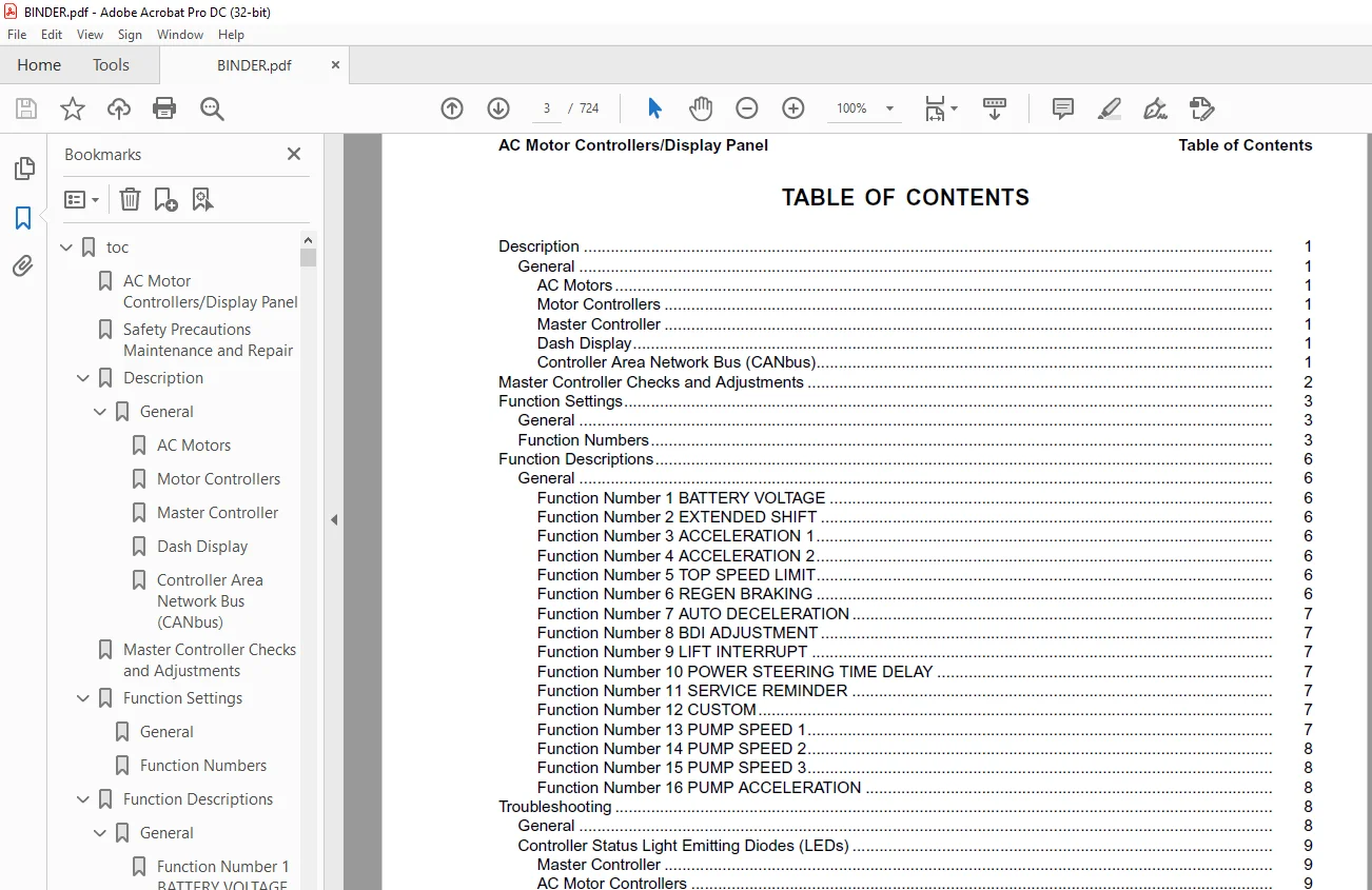
TABLE OF CONTENTS:
Yale Forklift ERC 35-55 HG (B839) Service Manual – PDF DOWNLOAD
htoc 1
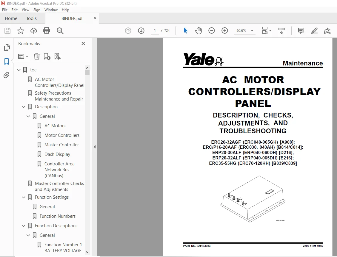
AC Motor Controllers/Display Panel 1
Safety Precautions Maintenance and Repair 2
Description 5
General 5
AC Motors 5
Motor Controllers 5
Master Controller 5
Dash Display 5
Controller Area Network Bus (CANbus) 5
Master Controller Checks and Adjustments 6
Function Settings 7
General 7
Function Numbers 7
Function Descriptions 10
General 10
Function Number 1 BATTERY VOLTAGE 10
Function Number 2 EXTENDED SHIFT 10
Function Number 3 ACCELERATION 1 10
Function Number 4 ACCELERATION 2 10
Function Number 5 TOP SPEED LIMIT 10
Function Number 6 REGEN BRAKING 10
Function Number 7 AUTO DECELERATION 11
Function Number 8 BDI ADJUSTMENT 11
Function Number 9 LIFT INTERRUPT 11
Function Number 10 POWER STEERING TIME DELAY 11
Function Number 11 SERVICE REMINDER 11
Function Number 12 CUSTOM 11
Function Number 13 PUMP SPEED 1 11
Function Number 14 PUMP SPEED 2 12
Function Number 15 PUMP SPEED 3 12
Function Number 16 PUMP ACCELERATION 12
Troubleshooting 12
General 12
Controller Status Light Emitting Diodes (LEDs) 13
Master Controller 13
AC Motor Controllers 13
Status Codes 19
AC Motor Controllers Status Code Charts 21
Troubleshooting When Dash and/or Lift Truck is not Operational 42
Typical Symptoms 42
Truck Runs but Dash Display is not Operational, or Only Displays 42
Truck Does Not Run and Dash is Not Operational or Only Displays 43
Hydraulics Operate Normally, Traction Does Not Operate Correctly 44
Traction Operates Normally, Hydraulics do Not Operate Correctly, 44
AC Transistor Motor Controller Replacement 44
General 44
General Maintenance Instructions 50
Special Precautions 50
Fuses 51
Fan Test 51
Contactors 51
Repair 51
Thermal Sensors 55
Motor Controller, Replace 55
Display Panel 56
General 56
Premium Display Panel 56
Standard Display Panel 56
Display Functions and Features 57
Key-On Initialization 57
Standard Display 58
Premium Display 58
Lift Truck Inspection Function 59
Access to Service Functions 59
Service Functions 59
Service Functions 60
Performance Modes 62
Battery Discharge Indicator (BDI) 62
Hourmeter 63
Dash Display Service Menu Navigation 69
General 69
Moving Through Menu Selections 69
Editing and Adding Information 69
tables 1
Table 1 Factory Parameters for ERP20-30ALF (ERP040-060DH) (D216 7
Table 2 Factory Setting for ERC020-032AGF (ERC40-65GH) (A908) 8
Table 3 Factory Setting for ERC/P16-20AAF (ERC030-040AH) (B814/ 8
Table 4 Factory Parameters for ERC35-55HG (ERC70-120HH) (B839/C 9
Table 5 List of Status Codes 19
Table 6 42-Pin Connections/Descriptions for Master Controller 52
Table 7 Pin Connections/Descriptions for 72/80 (Gen IV) Volt Mo 54
Table 8 Pin Connections/Descriptions for 36/48 and 72v/80v (Gen 54
toc 73
AC Motor Repair 73
Safety Precautions Maintenance and Repair 74
General 77
AC Motor Repair 77
Disassemble 77
Assemble 81
Troubleshooting 83
toc 87
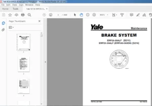
Brake System 87
Safety Precautions Maintenance and Repair 88
General 91
Description and Operation 91
Brake Booster and Master Cylinder 91
Master Cylinder 91
Service Brake Assembly 91
Parking Brake 95
Seat Brake 96
Brake Shoe Assemblies Repair 97
Remove and Disassemble 97
Clean and Inspect 97
Assemble and Install 99
Master Cylinder Repair103
Master Cylinder For Lift Truck Models GC/GLC70-120LG/MG (B818) a103
Remove103
Disassemble103
Assemble104
Install104
Master Cylinder For Lift Truck Models ERC70-120HD, ERC70-120HG (105
Remove and Disassemble105
Clean and Inspect106
Assemble and Install106
Brake Booster Repair106
Remove106
Disassemble106
Clean and Inspect107
Assemble108
Install108
Brake System Air Removal108
Brake Pedal Adjustment108
Brake Pedal GP/GLP/GDP70-120LG/MG (B813) With Manual Transmissio108
Brake Shoes Adjustment110
Parking Brake Adjustment110
Parking Brake Adjustment, Lift Truck Models GC/GLC70-120LG/MG (B110
Parking Brake Lever and Switch Adjustment ERC70-120HD and ERC70-111
Seat Brake Assembly112
Remove112
Clean and Inspect112
Install112
Adjustments114
Solenoid Adjustment114
Traction cutoff Switch Adjustment114
Cable Adjustment114
Brake Booster Relief Valve Check117
Troubleshooting117
toc123
Capacities and Specifications123
Safety Precautions Maintenance and Repair124
Lift Truck Lifting Capacity127
Counterweight Weights127
Tire Sizes127
Capacities128
Hydraulic System128
Steering System129
Specifications129
Turning Radius129
Mast Speeds130
Maximum Carriage and Tilt Creep Rates131
Battery Specifications131
Traction Motor Speed132
Battery Current at Hoist Relief132
Torque Specifications132
Brake System132
Differential133
Drive Axle133
Frame133
Mast133
Main Control Valve133
Steering System133
Tilt Cylinders134
Hydraulic System134
Electrical System134
tables123
Table 1 Manual Control Valve128
Table 2 E-Hydraulic Control Valve128
toc137
Diagrams137
Safety Precautions Maintenance and Repair138
toc177
Drive Axle, Speed Reducer, and Differential177
Safety Precautions Maintenance and Repair178
General181
Description181
Drive Axle, Speed Reducer, and Differential Repair182
Remove182
General182
Traction Motor, Speed Reducer, and Differential183
Motor, Speed Reducer, and Differential, Remove183
Disassemble186
Speed Reducer186
Differential187
Clean188
Inspect188
Assemble188
Speed Reducer188
Input Gear, Install188
New Pinion, Install188
Differential191
Drive Axle Housing194
Remove194
Clean195
Inspect195
Assemble195
Troubleshooting198
tables177
Table 1 Pinion Assembly Shims Adjustment190
Table 2 Ring and Pinion Tooth Contact Adjustment192
toc201
Electrical System (Trucks With AC Controllers)201
Safety Precautions Maintenance and Repair202
General205
Description206
Features of the Display Panels206
Other Control Components207
Display Panel and Key Switch Replacement208
Display Panel, Replace208
Key Switch, Replace210
Controller Replacement210
Traction and Pump Motor Controller Replacement210
Master Controller, Replace216
Master Controller, Remove ERP20-30ALF (ERP040-060DH) (D216), ERP216
Master Controller, Install ERP20-30ALF (ERP040-060DH) (D216), ER216
Master Controller, Remove ERC/P16-20AAF (ERC030-040AH) (B814/C81218
Master Controller, Install ERC/P16-20AAF (ERC030-040AH) (B814/C8218
Master Controller, Remove ERC35-55HG (ERC070-120HH) (B839/C839)220
Master Controller, Install ERC35-55HG (ERC070-120HH) (B839/C839)220
Control Components Replacement221
General221
Start Switch, Replace221
Brake Light Switch, Replace222
Seat Switch, Replace222
Parking Brake Switch, Replace223
Foot Directional Control Pedal Direction Switches, Replace225
Steering Column Direction Control Switches, Replace228
Remove228
Install228
Brake Fluid Switch, Replace230
Brush Wear and Over Temperature Sensors (DC Pump Motor Only)230
Rocker Switches for Lights, Replace230
Accelerator Position Sensor, Replace231
On-Demand Steering Sensor, Replace232
Lights, Converter, Relay, and Reverse Alarm232
Brake, Tail, and Reverse Light Assembly, Replace233
Incandescent Assembly233
LED Assembly – Remove235
LED Assembly – Install235
Strobe Light Assembly, Replace238
Wire Harness Repair239
Del-City Crimp-Solder-Shrink Splice239
Front, Rear Driving Light or Spot Light Assemblies, Replace240
Converter, Replace240
Remove, Lift Truck Models ERP20-30ALF (ERP040-060DH) (D216), ERP240
Install, Lift Truck Models ERP20-30ALF (ERP040-060DH) (D216), ER242
Remove, Lift Truck Models ERC20-32AGF (ERC040-065GH) (A908) and 242
Install, Lift Truck Models ERC20-32AGF (ERC040-065GH) (A908) and242
Remove, Lift Truck Models ERC35-55HG (ERC70-120HH) (B839/C839)244
Install, Lift Truck Models ERC35-55HG (ERC70-120HH) (B839/C839)244
Reverse Relay, Replace245
Lift Truck Models ERC20-32AGF (ERC040-065GH) (A908), ERC/P16-20A245
Lift Truck Models ERC35-55HG (ERC70-120HH) (B839/C839)245
Backup Alarm, Replace247
Horn and Horn Button, Replace247
Horn Replacement for Lift Trucks ERP20-30ALF (ERP040-060DH) (D21247
Horn Replacement for Lift Trucks ERC35-55HG (ERC70-120HH) (B839/249
Horn Switch and Cover, Replace250
Hydraulic Pump Switches251
Fan Power Supply, Replace251
Remove, Lift Truck Models ERC35-55HG (ERC70-120HH) (B839/C839)251
Install, Lift Truck Models ERC35-55HG (ERC70-120HH) (B839/C839)251
Remove, Lift Truck Models ERP20-30ALF (ERP040-060DH) (D216) and 252
Install, Lift Truck Models ERP20-30ALF (ERP040-060DH) (D216) and253
Remove, Lift Truck Models ERC20-32AGF (ERC040-065GH) (A908)253
Install, Lift Truck Models ERC20-32AGF (ERC040-065GH) (A908)253
Control and Power Fuse Check254
Fuse Locations254
Brake Light Switch Adjustment260
Seat Switch Check261
Seat Brake Adjustment261
Parking Brake Switch Adjustment262
Direction Switches Check262
Foot Directional Control Pedal262
Steering Column263
Foot Directional Control Pedal or Accelerator Pedal Adjustment263
Accelerator Position Sensor Adjustment and Start Switch Adjustme264
Acceleration Position Sensor, Adjust264
Start Switch, Adjust266
tables201
Table 1 Wire Splice Size239
toc269
Frame269
Safety Precautions Maintenance and Repair270
General273
Description273
Overhead Guard Replacement275
Remove275
Install276
Battery and Operator Restraint, Hood and Seat Brake Repair277
Battery Restraint and Hood Repair277
Operator Restraint System and Seat Assembly280
Automatic Locking Retractor (ALR)280
Emergency Locking Retractor (ELR)280
Seat Brake Repair281
Counterweight Replacement281
Remove281
Install282
Traction Motor Repair282
Remove282
Install283
Hydraulic Tank Repair284
Inspect284
Small Leaks, Repair284
Large Leaks, Repair284
Clean284
Steam Method285
Chemical Solution Method285
Additional Preparations For Repair285
Safety Label Replacement286
Battery Specifications288
tables269
Table 1 Torque Values276
Table 2 Weight of Counterweights281
Table 3 Battery Specifications*288
toc291
Hydraulic System291
Safety Precautions Maintenance and Repair292
General295
Description295
Hydraulic System295
Operation303
Hydraulic System303
Hydraulic Gear Pump309
Steering Pump309
Hydraulic Tank Repair317
Tank, Remove [ERC/P16-20AAF (ERC030-040AF, AG/BG) (A814); ERC/P1317
Tank, Remove [ERP20-30ALF (B216) and ERP20-30ALF (ERP040-060DH) 319
Tank, Remove [ERP20-32ALF (ERP040-065DH) (E216)]320
Hydraulic Tank [ERC35-55HG (ERC70-120HH) (B839/C839)]320
Inspect321
Small Leaks, Repair322
Large Leaks, Repair322
Clean322
Steam Method322
Chemical Solution Method323
Additional Methods for Tank Repair323
Tank, Install [ERC/P16-20AAF (ERC030-040AF, AG/BG) (A814); ERC/P323
Tank, Install [ERP20-30ALF (B216) and ERP20-30ALF (ERP040-060DH)324
Tank, Install [ERP20-32ALF (ERP040-065DH) (E216)]324
Filter Replacement325
All Lift Trucks Except [ERC35-55HG (ERC70-120HH) (B839/C839); ER325
Remove325
Install326
Lift Truck Models [ERC35-55HG (ERC70-120HH) (B839/C839)]326
Remove326
Install326
Lift truck Models [ERC20-32AGF (ERC040-065GH) (A908) and ERC/P16327
Remove327
Install327
Lift Truck Models [ERP20-32ALF (ERP040-065DH) (E216)]329
Remove329
Install329
Hydraulic Pump Repair332
Hydraulic Pump, Remove [ERC/P16-20AAF (ERC030-040AF, AG/BG) (A81332
Hydraulic Pump, Disassemble ERC/P16-20AAF (ERC030-040AF, AG/BG) 332
Inspect334
Clean334
Pump Seal Replace and Pump Assemble334
Assemble Pump on Motor334
Hydraulic Pump and Motor, Install [ERC/P16-20AAF (ERC030-040AF, 336
Hydraulic Pump, Remove [ERP20-30ALF (B216); ERP20-30ALF (ERP040-337
Hydraulic Pump, Disassemble [ERC35-55HG (ERC70-120HH) (B839/C839338
Hydraulic Pump, Inspect [ERC35-55HG (ERC70-120HH) (B839/C839) an340
Hydraulic Pump, Clean [ERC35-55HG (ERC70-120HH) (B839/C839) and 340
Hydraulic Pump, Assemble [ERC35-55HG (ERC70-120HH) (B839/C839) a340
Hydraulic Pump and Motor, Install [ERP20-30ALF (B216); ERP20-30A340
Main Control Valve Repair342
Steering Pump Repair342
Pump, Remove and Disassemble [ERC/P16-20AAF (ERC030-040AF, ERC03342
Pump, Remove and Disassemble [ERP20-30ALF (B216); ERP20-30ALF (E344
Pump, Assemble and Install346
Steering Control Unit Replacement347
Remove347
Install347
Steering Cylinder Repair353
Main Control Valve Check and Adjust353
Steering Relief Valve Check and Adjust354
Specifications354
Relief Valve Pressures*354
Hydraulic Tank Capacity (dipstick full mark)355
Hydraulic Pump Capacities – All Models Except ERC35-55HG (ERC70-355
Hydraulic Pump Capacities – Models ERC35-55HG (ERC70-120HH) (B83355
Troubleshooting355
Steering355
Steering Housing and Steering Control Unit356
Hydraulic System357
toc363
Industrial Battery363
Safety Precautions Maintenance and Repair364
General367
Lead-Acid Batteries367
Specific Gravity368
Chemical Reaction in a Cell368
Electrical Terms369
Battery Selection370
Battery Voltage371
Battery as a Counterweight371
Battery Ratings372
Kilowatt-Hours372
Battery Maintenance372
Safety Procedures372
Maintenance Records373
New Battery373
Cleaning Battery373
Adding Water to Battery375
Hydrometer376
Battery Temperature376
Charging Battery377
Types of Battery Charges378
Methods of Charging379
Troubleshooting Charger380
Knowing When Battery Is Fully Charged380
Where to Charge Batteries380
Equipment Needed380
Battery Connectors381
Battery Care381
tables363
Table 1 Battery Capacity Terms372
toc385
Lift Cylinders385
Safety Precautions Maintenance and Repair386
Safety Procedures When Working Near Mast389
General391
Description391
Lowering Control Valve (Velocity Fuse)391
Lift Cylinder Repair394
Remove394
Disassemble395
Assemble395
Install395
Lift System Leak Check396
Troubleshooting397
toc401
Manual hydraulic Control Valve401
Safety Precautions Maintenance and Repair402
General405
Description405
Operation407
Lift Section409
Tilt Section410
Tilt Backward410
Tilt Forward410
Relief Valve412
Solenoid Valve for Auxiliary Function413
Main Control Valve Repair414
Remove and Disassemble – Control Valve Without OPS Solenoid414
Remove and Disassemble – Control Valve With OPS Solenoid414
Clean and Inspect416
Assemble – Control Valve Without OPS416
Assemble – Control Valve With OPS416
Install417
Solenoid Valve for Auxiliary Function Repair417
Remove and Disassemble417
Assemble and Install419
Troubleshooting419
Pressure Relief Valve Check and Adjustment420
Primary Relief Valve420
Secondary Relief Valve420
Control Lever Arrangement and Adjustment421
Specifications423
Troubleshooting423
toc429
Masts429
Safety Precautions Maintenance and Repair430
General433
Description and Operation433
Carriages433
Two-Stage Mast With Limited Free-Lift433
Two-Stage Mast With Full Free-Lift434
Three-Stage Mast With Full Free-Lift435
Safety Procedures When Working Near Mast437
Fork Replacement439
Remove440
Install440
Carriage Repair441
Remove441
Sideshift Carriage Repair443
Remove443
Disassemble443
Assemble443
Install443
Two-Stage Mast With Limited Free-Lift Repair445
Remove, GLP/GDP35-55LJ/MJ (GP/GLP/GDP070-120LJ/MJ) Model Lift 445
Remove, GC070-120LJ/MJ, ERC070-120HG (A839), and ERC35-55HG (ERC447
Disassemble450
Clean and Inspect450
Assemble451
Install, GLP/GDP35-55LJ/MJ (GP/GLP/GDP070-120LJ/MJ) Lift Truck452
Install, GC070-120LJ/MJ, ERC070-120HG (A839), and ERC35-55HG (ER454
Two-Stage Mast With Full Free-Lift Repair456
Remove456
Disassemble456
Clean and Inspect458
Assemble458
Install458
Three-Stage Mast With Full Free-Lift Repair460
Remove460
Disassemble460
Clean and Inspect464
Assemble464
Install465
Mast Operation Check471
Lift and Tilt System Leak Check472
Lift System472
Tilt System473
Tilt Cylinder Stroke and Backward Tilt Angle Adjustment474
Lift Chain Adjustments476
Mast Adjustments478
Carriage Adjustment480
Troubleshooting481
tables429
Table 1 Tilt Cylinder Leak Check Specifications, GC070-120LJ/MJ473
Table 2 Hook-Type Carriage Chain Adjustment476
Table 3 Pin-Type Carriage Chain Adjustment477
toc487
Metric and Inch (SAE) Fasteners487
Safety Precautions Maintenance and Repair488
General491
Threaded Fasteners491
Nomenclature, Threads491
Strength Identification492
Cotter (Split) Pins492
Fastener Torque Tables497
Conversion Table499
tables487
Table 1 Bolts and Screws493
Table 2 Studs and Nuts494
Table 3 Torque Nuts495
Table 4 Torque Nuts with Nylon Insert496
Table 5 Torque Values for Metric Fasteners*497
Table 6 Torque Values for Inch Fasteners*498
Table 7 Conversion Table for Metric and English Units499
Table 8 Cotter Pin Dimensional Data500
Table 9 Cotter Pin Dimensional Data501
Table 10 Cotter Pin Dimensional Data502
Table 11 Cotter Pin Dimensional Data504
toc507
Periodic Maintenance507
Safety Precautions Maintenance and Repair508
General513
How to Move Disabled Lift Truck513
How to Tow Lift Truck513
How to Put Lift Trucks on Blocks514
How to Raise Drive Tires514
How to Raise Steering Tires514
How to Clean a Lift Truck515
Maintenance Schedule516
Maintenance Procedures Every 8 Hours or Daily520
General520
How to Make Checks With Key Switch OFF521
Tires and Wheels521
Forks521
Remove521
Inspect521
Install522
Adjust522
Inspection of Mast, Mast Pivots, Header Hoses and Lift Chains523
Safety Labels523
Steering Column Latch523
Operator Restraint System524
Automatic Locking Retractor (ALR)524
Emergency Locking Retractor (ELR)524
Battery Restraint System525
Battery526
Hydraulic System527
How to Make Checks With Key Switch ON528
Horn, Lights, and Alarm528
Steering System529
Service Brakes529
Parking Brake529
Seat Brake529
Control Levers and Pedals529
Direction and Speed Control Pedals529
Lift System Operation529
Oil Leaks530
First Service After First 100 Hours of Operation530
Change Hydraulic Oil and Filter530
Lift Truck Models ERC35-55HG (ERC70-120HH) (C839)530
Remove530
Install532
Lift Truck Models ERC35-55HG (ERC70-120HH) (B839)533
Remove533
Install534
Maintenance Procedures Every 500 Hours or 3 Months535
Wheel Nuts535
Header Hose Checks535
Mast Lubrication535
Integral Sideshift Carriage538
Brake Fluid539
Other Lubrication539
Maintenance Procedures Every 1000 Hours or 6 Months539
Differential and Speed Reducer539
Lift Chains539
Wear Check539
Lubrication540
Forks540
Parking Brake540
Brake Linkage Shafts541
Steering Spindles and Tie Rod Ends541
Seat Rails541
Seat Plate Hinges541
Electrical Inspection542
Contactors542
Maintenance Procedures Every 2000 Hours or Yearly544
Brake Fluid544
Hydraulic System545
Hydraulic Tank Breather, Lift Truck Models ERC35-55HG (ERC70-120545
Change Hydraulic Oil and Hydraulic Oil Filter, Lift Truck Models545
Remove545
Install546
Hydraulic Tank Breather, Lift Truck Models ERC35-55HG (ERC70-120547
Remove547
Install547
Change Hydraulic Oil and Hydraulic Oil Filter, Lift Truck Models547
Remove547
Install549
Differential and Speed Reducer549
Service Brakes550
Wheel Bearings550
Steer Wheels, Lubrication550
Drive Wheels, Lubrication550
Lift Chains550
Battery Maintenance551
How to Charge Battery551
How to Change Battery552
Safety Procedures When Working Near Mast555
Lift and Tilt System Leak Check558
Check Lift Cylinders for Leaks558
Check Tilt Cylinders for Leaks558
Lift Chain Adjustments559
Welding Repairs560
Overhead Guard Changes561
Wheels and Tires561
General561
Remove Wheels From Lift Truck561
Remove Tire From Wheel and Install Tire on Wheel561
Remove561
Install561
Install Wheels562
tables507
Table 1 Maintenance Schedule517
Table 2 Battery Specifications*555
Table 3 Hook-Type Carriage Chain Adjustment560
toc565
Steering Axle565
Safety Precautions Maintenance and Repair566
General569
Description569
Steering Axle Assembly Repair574
Steering Axle GP/GLP/GDP070-110LG/MG (B813), GC/GLC070-120LG/MG 574
Remove574
Install574
Steering Axle GDP60-70CA (GP/GLP/GDP135-155CA) (A878, B878), GLP575
Remove575
Install575
Wheels and Hubs Repair (All Units)576
Remove and Disassemble576
Clean576
Inspect576
Assemble and Install576
Spindles and Bearings Repair (All Units)578
Remove578
Clean578
Assemble and Install579
Tie Rods Repair (All Units)580
Remove580
Clean580
Install580
Steering Cylinder Repair583
Remove and Disassemble583
Clean and Inspect583
Assemble and Install583
Troubleshooting584
toc589
Steering Housing and Control Unit589
Safety Precautions Maintenance and Repair590
General593
Description593
Operation594
Steering Wheel and Column Assembly Repair595
Assembly Components, Remove595
Steering Control Unit, Disassemble600
Steering Control Unit, Clean600
Steering Control Unit, Assemble600
Assembly Components, Install602
System Air Removal604
Troubleshooting604
toc609
Steering System for AC Electric Lift Trucks609
Safety Precautions Maintenance and Repair610
General613
Description614
Steering Wheel and Column Assembly Repair615
General615
Assembly Components, Remove617
Assembly Components, Install618
Power Steering Motor and Pump619
Description619
Remove619
Disassemble622
Install622
Power Steering Pump, Repair622
Seal, Replace623
Steering System Air Removal624
Steering Pressure Check624
Steering Motor Circuits Check625
Troubleshooting626
toc631
Tilt Cylinders631
Safety Precautions Maintenance and Repair632
General635
Description635
Tilt Cylinder Repair635
Remove635
Disassemble635
Clean635
Assemble636
Tilt Cylinders With O-Ring or Single-Lip Seals636
Tilt Cylinders637
Install638
Tilt Cylinder Leak Check640
Tilt Cylinder Stroke and Mast Tilt Angle Adjustment641
Torque Specifications641
Piston Rod Nut641
Retainer641
Troubleshooting642
tables631
Table 1 Movement Rates (Maximum) for Tilt Cylinders640
toc647
Troubleshooting and Adjustments Using the AC Controls Program (E647
Safety Precautions Maintenance and Repair648
General651
Computer Requirements651
Software, Install651
Language Selection651
Demo Mode652
Connect PC to Lift Truck656
Starting AC Controls Program658
Lift Truck Control Setup663
Change Lift Truck Serial Number or Hourmeter663
Setting Factory Default Values or Changing Lift Truck Parameters664
Create New Custom Lift Truck Configuration670
Lift Truck Configuration Properties673
Import New Lift Truck Configuration From Disk676
Delete Custom Lift Truck Configuration or Password File678
Dash Display681
Custom Display Languages681
Download Display Language683
Clear Operator Log683
Password Functions686
Enable/Disable Password and Lift Truck Inspection Functions686
Truck Inspection Checklist686
Password686
Password Properties686
Create New Password File691
Download Passwords692
Upload Passwords694
Reports Menu696
Devices Report696
Custom Report696
Password Report696
Operator Report703
Current Settings Report706
Status Code Report710
Status Codes Log713
Troubleshooting715
Diagnostics715
Help Menu718
General718
Contents718
Technical Support718
About Electric Truck AC Controls Program718htoc 1
AC Motor Controllers/Display Panel 1
Safety Precautions Maintenance and Repair 2
Description 5
General 5
AC Motors 5
Motor Controllers 5
Master Controller 5
Dash Display 5
Controller Area Network Bus (CANbus) 5
Master Controller Checks and Adjustments 6
Function Settings 7
General 7
Function Numbers 7
Function Descriptions 10
General 10
Function Number 1 BATTERY VOLTAGE 10
Function Number 2 EXTENDED SHIFT 10
Function Number 3 ACCELERATION 1 10
Function Number 4 ACCELERATION 2 10
Function Number 5 TOP SPEED LIMIT 10
Function Number 6 REGEN BRAKING 10
Function Number 7 AUTO DECELERATION 11
Function Number 8 BDI ADJUSTMENT 11
Function Number 9 LIFT INTERRUPT 11
Function Number 10 POWER STEERING TIME DELAY 11
Function Number 11 SERVICE REMINDER 11
Function Number 12 CUSTOM 11
Function Number 13 PUMP SPEED 1 11
Function Number 14 PUMP SPEED 2 12
Function Number 15 PUMP SPEED 3 12
Function Number 16 PUMP ACCELERATION 12
Troubleshooting 12
General 12
Controller Status Light Emitting Diodes (LEDs) 13
Master Controller 13
AC Motor Controllers 13
Status Codes 19
AC Motor Controllers Status Code Charts 21
Troubleshooting When Dash and/or Lift Truck is not Operational 42
Typical Symptoms 42
Truck Runs but Dash Display is not Operational, or Only Displays 42
Truck Does Not Run and Dash is Not Operational or Only Displays 43
Hydraulics Operate Normally, Traction Does Not Operate Correctly 44
Traction Operates Normally, Hydraulics do Not Operate Correctly, 44
AC Transistor Motor Controller Replacement 44
General 44
General Maintenance Instructions 50
Special Precautions 50
Fuses 51
Fan Test 51
Contactors 51
Repair 51
Thermal Sensors 55
Motor Controller, Replace 55
Display Panel 56
General 56
Premium Display Panel 56
Standard Display Panel 56
Display Functions and Features 57
Key-On Initialization 57
Standard Display 58
Premium Display 58
Lift Truck Inspection Function 59
Access to Service Functions 59
Service Functions 59
Service Functions 60
Performance Modes 62
Battery Discharge Indicator (BDI) 62
Hourmeter 63
Dash Display Service Menu Navigation 69
General 69
Moving Through Menu Selections 69
Editing and Adding Information 69
tables 1
Table 1 Factory Parameters for ERP20-30ALF (ERP040-060DH) (D216 7
Table 2 Factory Setting for ERC020-032AGF (ERC40-65GH) (A908) 8
Table 3 Factory Setting for ERC/P16-20AAF (ERC030-040AH) (B814/ 8
Table 4 Factory Parameters for ERC35-55HG (ERC70-120HH) (B839/C 9
Table 5 List of Status Codes 19
Table 6 42-Pin Connections/Descriptions for Master Controller 52
Table 7 Pin Connections/Descriptions for 72/80 (Gen IV) Volt Mo 54
Table 8 Pin Connections/Descriptions for 36/48 and 72v/80v (Gen 54
toc 73
AC Motor Repair 73
Safety Precautions Maintenance and Repair 74
General 77
AC Motor Repair 77
Disassemble 77
Assemble 81
Troubleshooting 83
toc 87
Brake System 87
Safety Precautions Maintenance and Repair 88
General 91
Description and Operation 91
Brake Booster and Master Cylinder 91
Master Cylinder 91
Service Brake Assembly 91
Parking Brake 95
Seat Brake 96
Brake Shoe Assemblies Repair 97
Remove and Disassemble 97
Clean and Inspect 97
Assemble and Install 99
Master Cylinder Repair103
Master Cylinder For Lift Truck Models GC/GLC70-120LG/MG (B818) a103
Remove103
Disassemble103
Assemble104
Install104
Master Cylinder For Lift Truck Models ERC70-120HD, ERC70-120HG (105
Remove and Disassemble105
Clean and Inspect106
Assemble and Install106
Brake Booster Repair106
Remove106
Disassemble106
Clean and Inspect107
Assemble108
Install108
Brake System Air Removal108
Brake Pedal Adjustment108
Brake Pedal GP/GLP/GDP70-120LG/MG (B813) With Manual Transmissio108
Brake Shoes Adjustment110
Parking Brake Adjustment110
Parking Brake Adjustment, Lift Truck Models GC/GLC70-120LG/MG (B110
Parking Brake Lever and Switch Adjustment ERC70-120HD and ERC70-111
Seat Brake Assembly112
Remove112
Clean and Inspect112
Install112
Adjustments114
Solenoid Adjustment114
Traction cutoff Switch Adjustment114
Cable Adjustment114
Brake Booster Relief Valve Check117
Troubleshooting117
toc123
Capacities and Specifications123
Safety Precautions Maintenance and Repair124
Lift Truck Lifting Capacity127
Counterweight Weights127
Tire Sizes127
Capacities128
Hydraulic System128
Steering System129
Specifications129
Turning Radius129
Mast Speeds130
Maximum Carriage and Tilt Creep Rates131
Battery Specifications131
Traction Motor Speed132
Battery Current at Hoist Relief132
Torque Specifications132
Brake System132
Differential133
Drive Axle133
Frame133
Mast133
Main Control Valve133
Steering System133
Tilt Cylinders134
Hydraulic System134
Electrical System134
tables123
Table 1 Manual Control Valve128
Table 2 E-Hydraulic Control Valve128
toc137
Diagrams137
Safety Precautions Maintenance and Repair138
toc177
Drive Axle, Speed Reducer, and Differential177
Safety Precautions Maintenance and Repair178
General181
Description181
Drive Axle, Speed Reducer, and Differential Repair182
Remove182
General182
Traction Motor, Speed Reducer, and Differential183
Motor, Speed Reducer, and Differential, Remove183
Disassemble186
Speed Reducer186
Differential187
Clean188
Inspect188
Assemble188
Speed Reducer188
Input Gear, Install188
New Pinion, Install188
Differential191
Drive Axle Housing194
Remove194
Clean195
Inspect195
Assemble195
Troubleshooting198
tables177
Table 1 Pinion Assembly Shims Adjustment190
Table 2 Ring and Pinion Tooth Contact Adjustment192
toc201
Electrical System (Trucks With AC Controllers)201
Safety Precautions Maintenance and Repair202
General205
Description206
Features of the Display Panels206
Other Control Components207
Display Panel and Key Switch Replacement208
Display Panel, Replace208
Key Switch, Replace210
Controller Replacement210
Traction and Pump Motor Controller Replacement210
Master Controller, Replace216
Master Controller, Remove ERP20-30ALF (ERP040-060DH) (D216), ERP216
Master Controller, Install ERP20-30ALF (ERP040-060DH) (D216), ER216
Master Controller, Remove ERC/P16-20AAF (ERC030-040AH) (B814/C81218
Master Controller, Install ERC/P16-20AAF (ERC030-040AH) (B814/C8218
Master Controller, Remove ERC35-55HG (ERC070-120HH) (B839/C839)220
Master Controller, Install ERC35-55HG (ERC070-120HH) (B839/C839)220
Control Components Replacement221
General221
Start Switch, Replace221
Brake Light Switch, Replace222
Seat Switch, Replace222
Parking Brake Switch, Replace223
Foot Directional Control Pedal Direction Switches, Replace225
Steering Column Direction Control Switches, Replace228
Remove228
Install228
Brake Fluid Switch, Replace230
Brush Wear and Over Temperature Sensors (DC Pump Motor Only)230
Rocker Switches for Lights, Replace230
Accelerator Position Sensor, Replace231
On-Demand Steering Sensor, Replace232
Lights, Converter, Relay, and Reverse Alarm232
Brake, Tail, and Reverse Light Assembly, Replace233
Incandescent Assembly233
LED Assembly – Remove235
LED Assembly – Install235
Strobe Light Assembly, Replace238
Wire Harness Repair239
Del-City Crimp-Solder-Shrink Splice239
Front, Rear Driving Light or Spot Light Assemblies, Replace240
Converter, Replace240
Remove, Lift Truck Models ERP20-30ALF (ERP040-060DH) (D216), ERP240
Install, Lift Truck Models ERP20-30ALF (ERP040-060DH) (D216), ER242
Remove, Lift Truck Models ERC20-32AGF (ERC040-065GH) (A908) and 242
Install, Lift Truck Models ERC20-32AGF (ERC040-065GH) (A908) and242
Remove, Lift Truck Models ERC35-55HG (ERC70-120HH) (B839/C839)244
Install, Lift Truck Models ERC35-55HG (ERC70-120HH) (B839/C839)244
Reverse Relay, Replace245
Lift Truck Models ERC20-32AGF (ERC040-065GH) (A908), ERC/P16-20A245
Lift Truck Models ERC35-55HG (ERC70-120HH) (B839/C839)245
Backup Alarm, Replace247
Horn and Horn Button, Replace247
Horn Replacement for Lift Trucks ERP20-30ALF (ERP040-060DH) (D21247
Horn Replacement for Lift Trucks ERC35-55HG (ERC70-120HH) (B839/249
Horn Switch and Cover, Replace250
Hydraulic Pump Switches251
Fan Power Supply, Replace251
Remove, Lift Truck Models ERC35-55HG (ERC70-120HH) (B839/C839)251
Install, Lift Truck Models ERC35-55HG (ERC70-120HH) (B839/C839)251
Remove, Lift Truck Models ERP20-30ALF (ERP040-060DH) (D216) and 252
Install, Lift Truck Models ERP20-30ALF (ERP040-060DH) (D216) and253
Remove, Lift Truck Models ERC20-32AGF (ERC040-065GH) (A908)253
Install, Lift Truck Models ERC20-32AGF (ERC040-065GH) (A908)253
Control and Power Fuse Check254
Fuse Locations254
Brake Light Switch Adjustment260
Seat Switch Check261
Seat Brake Adjustment261
Parking Brake Switch Adjustment262
Direction Switches Check262
Foot Directional Control Pedal262
Steering Column263
Foot Directional Control Pedal or Accelerator Pedal Adjustment263
Accelerator Position Sensor Adjustment and Start Switch Adjustme264
Acceleration Position Sensor, Adjust264
Start Switch, Adjust266
tables201
Table 1 Wire Splice Size239
toc269
Frame269
Safety Precautions Maintenance and Repair270
General273
Description273
Overhead Guard Replacement275
Remove275
Install276
Battery and Operator Restraint, Hood and Seat Brake Repair277
Battery Restraint and Hood Repair277
Operator Restraint System and Seat Assembly280
Automatic Locking Retractor (ALR)280
Emergency Locking Retractor (ELR)280
Seat Brake Repair281
Counterweight Replacement281
Remove281
Install282
Traction Motor Repair282
Remove282
Install283
Hydraulic Tank Repair284
Inspect284
Small Leaks, Repair284
Large Leaks, Repair284
Clean284
Steam Method285
Chemical Solution Method285
Additional Preparations For Repair285
Safety Label Replacement286
Battery Specifications288
tables269
Table 1 Torque Values276
Table 2 Weight of Counterweights281
Table 3 Battery Specifications*288
toc291
Hydraulic System291
Safety Precautions Maintenance and Repair292
General295
Description295
Hydraulic System295
Operation303
Hydraulic System303
Hydraulic Gear Pump309
Steering Pump309
Hydraulic Tank Repair317
Tank, Remove [ERC/P16-20AAF (ERC030-040AF, AG/BG) (A814); ERC/P1317
Tank, Remove [ERP20-30ALF (B216) and ERP20-30ALF (ERP040-060DH) 319
Tank, Remove [ERP20-32ALF (ERP040-065DH) (E216)]320
Hydraulic Tank [ERC35-55HG (ERC70-120HH) (B839/C839)]320
Inspect321
Small Leaks, Repair322
Large Leaks, Repair322
Clean322
Steam Method322
Chemical Solution Method323
Additional Methods for Tank Repair323
Tank, Install [ERC/P16-20AAF (ERC030-040AF, AG/BG) (A814); ERC/P323
Tank, Install [ERP20-30ALF (B216) and ERP20-30ALF (ERP040-060DH)324
Tank, Install [ERP20-32ALF (ERP040-065DH) (E216)]324
Filter Replacement325
All Lift Trucks Except [ERC35-55HG (ERC70-120HH) (B839/C839); ER325
Remove325
Install326
Lift Truck Models [ERC35-55HG (ERC70-120HH) (B839/C839)]326
Remove326
Install326
Lift truck Models [ERC20-32AGF (ERC040-065GH) (A908) and ERC/P16327
Remove327
Install327
Lift Truck Models [ERP20-32ALF (ERP040-065DH) (E216)]329
Remove329
Install329
Hydraulic Pump Repair332
Hydraulic Pump, Remove [ERC/P16-20AAF (ERC030-040AF, AG/BG) (A81332
Hydraulic Pump, Disassemble ERC/P16-20AAF (ERC030-040AF, AG/BG) 332
Inspect334
Clean334
Pump Seal Replace and Pump Assemble334
Assemble Pump on Motor334
Hydraulic Pump and Motor, Install [ERC/P16-20AAF (ERC030-040AF, 336
Hydraulic Pump, Remove [ERP20-30ALF (B216); ERP20-30ALF (ERP040-337
Hydraulic Pump, Disassemble [ERC35-55HG (ERC70-120HH) (B839/C839338
Hydraulic Pump, Inspect [ERC35-55HG (ERC70-120HH) (B839/C839) an340
Hydraulic Pump, Clean [ERC35-55HG (ERC70-120HH) (B839/C839) and 340
Hydraulic Pump, Assemble [ERC35-55HG (ERC70-120HH) (B839/C839) a340
Hydraulic Pump and Motor, Install [ERP20-30ALF (B216); ERP20-30A340
Main Control Valve Repair342
Steering Pump Repair342
Pump, Remove and Disassemble [ERC/P16-20AAF (ERC030-040AF, ERC03342
Pump, Remove and Disassemble [ERP20-30ALF (B216); ERP20-30ALF (E344
Pump, Assemble and Install346
Steering Control Unit Replacement347
Remove347
Install347
Steering Cylinder Repair353
Main Control Valve Check and Adjust353
Steering Relief Valve Check and Adjust354
Specifications354
Relief Valve Pressures*354
Hydraulic Tank Capacity (dipstick full mark)355
Hydraulic Pump Capacities – All Models Except ERC35-55HG (ERC70-355
Hydraulic Pump Capacities – Models ERC35-55HG (ERC70-120HH) (B83355
Troubleshooting355
Steering355
Steering Housing and Steering Control Unit356
Hydraulic System357
toc363
Industrial Battery363
Safety Precautions Maintenance and Repair364
General367
Lead-Acid Batteries367
Specific Gravity368
Chemical Reaction in a Cell368
Electrical Terms369
Battery Selection370
Battery Voltage371
Battery as a Counterweight371
Battery Ratings372
Kilowatt-Hours372
Battery Maintenance372
Safety Procedures372
Maintenance Records373
New Battery373
Cleaning Battery373
Adding Water to Battery375
Hydrometer376
Battery Temperature376
Charging Battery377
Types of Battery Charges378
Methods of Charging379
Troubleshooting Charger380
Knowing When Battery Is Fully Charged380
Where to Charge Batteries380
Equipment Needed380
Battery Connectors381
Battery Care381
tables363
Table 1 Battery Capacity Terms372
toc385
Lift Cylinders385
Safety Precautions Maintenance and Repair386
Safety Procedures When Working Near Mast389
General391
Description391
Lowering Control Valve (Velocity Fuse)391
Lift Cylinder Repair394
Remove394
Disassemble395
Assemble395
Install395
Lift System Leak Check396
Troubleshooting397
toc401
Manual hydraulic Control Valve401
Safety Precautions Maintenance and Repair402
General405
Description405
Operation407
Lift Section409
Tilt Section410
Tilt Backward410
Tilt Forward410
Relief Valve412
Solenoid Valve for Auxiliary Function413
Main Control Valve Repair414
Remove and Disassemble – Control Valve Without OPS Solenoid414
Remove and Disassemble – Control Valve With OPS Solenoid414
Clean and Inspect416
Assemble – Control Valve Without OPS416
Assemble – Control Valve With OPS416
Install417
Solenoid Valve for Auxiliary Function Repair417
Remove and Disassemble417
Assemble and Install419
Troubleshooting419
Pressure Relief Valve Check and Adjustment420
Primary Relief Valve420
Secondary Relief Valve420
Control Lever Arrangement and Adjustment421
Specifications423
Troubleshooting423
toc429
Masts429
Safety Precautions Maintenance and Repair430
General433
Description and Operation433
Carriages433
Two-Stage Mast With Limited Free-Lift433
Two-Stage Mast With Full Free-Lift434
Three-Stage Mast With Full Free-Lift435
Safety Procedures When Working Near Mast437
Fork Replacement439
Remove440
Install440
Carriage Repair441
Remove441
Sideshift Carriage Repair443
Remove443
Disassemble443
Assemble443
Install443
Two-Stage Mast With Limited Free-Lift Repair445
Remove, GLP/GDP35-55LJ/MJ (GP/GLP/GDP070-120LJ/MJ) Model Lift 445
Remove, GC070-120LJ/MJ, ERC070-120HG (A839), and ERC35-55HG (ERC447
Disassemble450
Clean and Inspect450
Assemble451
Install, GLP/GDP35-55LJ/MJ (GP/GLP/GDP070-120LJ/MJ) Lift Truck452
Install, GC070-120LJ/MJ, ERC070-120HG (A839), and ERC35-55HG (ER454
Two-Stage Mast With Full Free-Lift Repair456
Remove456
Disassemble456
Clean and Inspect458
Assemble458
Install458
Three-Stage Mast With Full Free-Lift Repair460
Remove460
Disassemble460
Clean and Inspect464
Assemble464
Install465
Mast Operation Check471
Lift and Tilt System Leak Check472
Lift System472
Tilt System473
Tilt Cylinder Stroke and Backward Tilt Angle Adjustment474
Lift Chain Adjustments476
Mast Adjustments478
Carriage Adjustment480
Troubleshooting481
tables429
Table 1 Tilt Cylinder Leak Check Specifications, GC070-120LJ/MJ473
Table 2 Hook-Type Carriage Chain Adjustment476
Table 3 Pin-Type Carriage Chain Adjustment477
toc487
Metric and Inch (SAE) Fasteners487
Safety Precautions Maintenance and Repair488
General491
Threaded Fasteners491
Nomenclature, Threads491
Strength Identification492
Cotter (Split) Pins492
Fastener Torque Tables497
Conversion Table499
tables487
Table 1 Bolts and Screws493
Table 2 Studs and Nuts494
Table 3 Torque Nuts495
Table 4 Torque Nuts with Nylon Insert496
Table 5 Torque Values for Metric Fasteners*497
Table 6 Torque Values for Inch Fasteners*498
Table 7 Conversion Table for Metric and English Units499
Table 8 Cotter Pin Dimensional Data500
Table 9 Cotter Pin Dimensional Data501
Table 10 Cotter Pin Dimensional Data502
Table 11 Cotter Pin Dimensional Data504
toc507
Periodic Maintenance507
Safety Precautions Maintenance and Repair508
General513
How to Move Disabled Lift Truck513
How to Tow Lift Truck513
How to Put Lift Trucks on Blocks514
How to Raise Drive Tires514
How to Raise Steering Tires514
How to Clean a Lift Truck515
Maintenance Schedule516
Maintenance Procedures Every 8 Hours or Daily520
General520
How to Make Checks With Key Switch OFF521
Tires and Wheels521
Forks521
Remove521
Inspect521
Install522
Adjust522
Inspection of Mast, Mast Pivots, Header Hoses and Lift Chains523
Safety Labels523
Steering Column Latch523
Operator Restraint System524
Automatic Locking Retractor (ALR)524
Emergency Locking Retractor (ELR)524
Battery Restraint System525
Battery526
Hydraulic System527
How to Make Checks With Key Switch ON528
Horn, Lights, and Alarm528
Steering System529
Service Brakes529
Parking Brake529
Seat Brake529
Control Levers and Pedals529
Direction and Speed Control Pedals529
Lift System Operation529
Oil Leaks530
First Service After First 100 Hours of Operation530
Change Hydraulic Oil and Filter530
Lift Truck Models ERC35-55HG (ERC70-120HH) (C839)530
Remove530
Install532
Lift Truck Models ERC35-55HG (ERC70-120HH) (B839)533
Remove533
Install534
Maintenance Procedures Every 500 Hours or 3 Months535
Wheel Nuts535
Header Hose Checks535
Mast Lubrication535
Integral Sideshift Carriage538
Brake Fluid539
Other Lubrication539
Maintenance Procedures Every 1000 Hours or 6 Months539
Differential and Speed Reducer539
Lift Chains539
Wear Check539
Lubrication540
Forks540
Parking Brake540
Brake Linkage Shafts541
Steering Spindles and Tie Rod Ends541
Seat Rails541
Seat Plate Hinges541
Electrical Inspection542
Contactors542
Maintenance Procedures Every 2000 Hours or Yearly544
Brake Fluid544
Hydraulic System545
Hydraulic Tank Breather, Lift Truck Models ERC35-55HG (ERC70-120545
Change Hydraulic Oil and Hydraulic Oil Filter, Lift Truck Models545
Remove545
Install546
Hydraulic Tank Breather, Lift Truck Models ERC35-55HG (ERC70-120547
Remove547
Install547
Change Hydraulic Oil and Hydraulic Oil Filter, Lift Truck Models547
Remove547
Install549
Differential and Speed Reducer549
Service Brakes550
Wheel Bearings550
Steer Wheels, Lubrication550
Drive Wheels, Lubrication550
Lift Chains550
Battery Maintenance551
How to Charge Battery551
How to Change Battery552
Safety Procedures When Working Near Mast555
Lift and Tilt System Leak Check558
Check Lift Cylinders for Leaks558
Check Tilt Cylinders for Leaks558
Lift Chain Adjustments559
Welding Repairs560
Overhead Guard Changes561
Wheels and Tires561
General561
Remove Wheels From Lift Truck561
Remove Tire From Wheel and Install Tire on Wheel561
Remove561
Install561
Install Wheels562
tables507
Table 1 Maintenance Schedule517
Table 2 Battery Specifications*555
Table 3 Hook-Type Carriage Chain Adjustment560
toc565
Steering Axle565
Safety Precautions Maintenance and Repair566
General569
Description569
Steering Axle Assembly Repair574
Steering Axle GP/GLP/GDP070-110LG/MG (B813), GC/GLC070-120LG/MG 574
Remove574
Install574
Steering Axle GDP60-70CA (GP/GLP/GDP135-155CA) (A878, B878), GLP575
Remove575
Install575
Wheels and Hubs Repair (All Units)576
Remove and Disassemble576
Clean576
Inspect576
Assemble and Install576
Spindles and Bearings Repair (All Units)578
Remove578
Clean578
Assemble and Install579
Tie Rods Repair (All Units)580
Remove580
Clean580
Install580
Steering Cylinder Repair583
Remove and Disassemble583
Clean and Inspect583
Assemble and Install583
Troubleshooting584
toc589
Steering Housing and Control Unit589
Safety Precautions Maintenance and Repair590
General593
Description593
Operation594
Steering Wheel and Column Assembly Repair595
Assembly Components, Remove595
Steering Control Unit, Disassemble600
Steering Control Unit, Clean600
Steering Control Unit, Assemble600
Assembly Components, Install602
System Air Removal604
Troubleshooting604
toc609
Steering System for AC Electric Lift Trucks609
Safety Precautions Maintenance and Repair610
General613
Description614
Steering Wheel and Column Assembly Repair615
General615
Assembly Components, Remove617
Assembly Components, Install618
Power Steering Motor and Pump619
Description619
Remove619
Disassemble622
Install622
Power Steering Pump, Repair622
Seal, Replace623
Steering System Air Removal624
Steering Pressure Check624
Steering Motor Circuits Check625
Troubleshooting626
toc631
Tilt Cylinders631
Safety Precautions Maintenance and Repair632
General635
Description635
Tilt Cylinder Repair635
Remove635
Disassemble635
Clean635
Assemble636
Tilt Cylinders With O-Ring or Single-Lip Seals636
Tilt Cylinders637
Install638
Tilt Cylinder Leak Check640
Tilt Cylinder Stroke and Mast Tilt Angle Adjustment641
Torque Specifications641
Piston Rod Nut641
Retainer641
Troubleshooting642
tables631
Table 1 Movement Rates (Maximum) for Tilt Cylinders640
toc647
Troubleshooting and Adjustments Using the AC Controls Program (E647
Safety Precautions Maintenance and Repair648
General651
Computer Requirements651
Software, Install651
Language Selection651
Demo Mode652
Connect PC to Lift Truck656
Starting AC Controls Program658
Lift Truck Control Setup663
Change Lift Truck Serial Number or Hourmeter663
Setting Factory Default Values or Changing Lift Truck Parameters664
Create New Custom Lift Truck Configuration670
Lift Truck Configuration Properties673
Import New Lift Truck Configuration From Disk676
Delete Custom Lift Truck Configuration or Password File678
Dash Display681
Custom Display Languages681
Download Display Language683
Clear Operator Log683
Password Functions686
Enable/Disable Password and Lift Truck Inspection Functions686
Truck Inspection Checklist686
Password686
Password Properties686
Create New Password File691
Download Passwords692
Upload Passwords694
Reports Menu696
Devices Report696
Custom Report696
Password Report696
Operator Report703
Current Settings Report706
Status Code Report710
Status Codes Log713
Troubleshooting715
Diagnostics715
Help Menu718
General718
Contents718
Technical Support718
About Electric Truck AC Controls Program718
S.M 11/24