![Yale NDR030GB, NR045GB [B861] Forklift Service Repair Manual PDF](https://heydownloads.com/wp-content/uploads/2024/07/Yale-Forklift-NDR030GB-NR045GB-B861-Service-Maintenance-Manual-2-1.webp)
![Yale NDR030GB, NR045GB [B861] Forklift Service Repair Manual PDF - Image 2](https://heydownloads.com/wp-content/uploads/2024/07/Yale-Forklift-NDR030GB-NR045GB-B861-Service-Maintenance-Manual-1-1.webp)
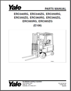
Yale NDR030GB, NR045GB [B861] Forklift Service Repair Manual PDF
$28.95
Yale Forklift NDR030GB, NR045GB [B861] Service Maintenance Manual – PDF DOWNLOAD
Description
Yale Forklift NDR030GB, NR045GB [B861] Service Maintenance Manual – PDF DOWNLOAD
FILE DETAILS:
Yale Forklift NDR030GB, NR045GB [B861] Service Maintenance Manual – PDF DOWNLOAD
Language : English
Pages : 492
Downloadable : Yes
File Type : PDF
IMAGES PREVIEW OF THE MANUAL:
TABLE OF CONTENTS:
Yale Forklift NDR030GB, NR045GB [B861] Service Maintenance Manual – PDF DOWNLOAD
toc 1
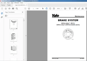
Brake System 1
Safety Precautions Maintenance and Repair 2
General 5
Brake Assembly 5
Inspect 5
Friction Pads 5
Remove 5
Install 6
Brake Assembly 7
Remove 7
Install 7
Brake Pedal Assembly 8
Remove 8
Install 9
Repair 9
Bushings and Spring 9
Remove 9
Install 9
Brake Switch Assembly 9
Remove 9
Install 9
Adjust 9
Troubleshooting 10
toc 13
Capacities and Specifications 13
Safety Precautions Maintenance and Repair 14
SEM Traction Motor Controllers Factory Values and Min/Max Ranges 17
Lift Capacities 18
Oil Capacities 19
Master Drive Unit Specifications 19
Hydraulic Tank Capacities 19
Articulation Adjustment 19
Hydraulic Systems Specifications 20
Reach Carriage Specifications 20
Battery Size Specifications 21
Tire Sizes 22
Fuses 22
Steering Pump Specifications 22
Hydraulic Control Valve/Relay Coil Resistance Values 23
toc 27
DC Motor Maintenance 27
Safety Precautions Maintenance and Repair 28
General 31
Brush and Commutator Inspection 31
Hydraulic Pump Motor and Traction Motor 31
Steering Pump Motor 34
Normal Commutator Surface 34
Commutator Problems 34
Brush Replacement 38
Stoning the Commutator 40
Motors Repair 42
Disassemble 42
Traction Motor and Hydraulic Pump Motor 42
Steering Pump Motor 46
Assemble 46
Traction Motor and Hydraulic Pump Motor 46
Steering Pump Motor 47
Brush Alignment, Traction and Hydraulic Motors 50
Tests for Damaged Field and Armature 50
Test for an Open Circuit in Armature 50
Test for Short Circuit in One Armature Winding 51
Test for Short Circuit to Armature Shaft 51
Test for Open Circuit in Field Coil 51
Test for Short Circuit in Field Coil 51
Test for Short Circuit between Field and Motor Case 52
Brush Holder Test 52
Troubleshooting 52
tables 27
Table 1 Normal Commutator Surfaces 33
Table 2 Commutator Problems 34
Table 3 Brush Wear Replacement Guide 38
toc 57
Diagrams 57
Safety Precautions Maintenance and Repair 58
toc 75
Electrical System 75
Safety Precautions Maintenance and Repair 76
General 81
Component Repair and Testing – General 82
Dash Display Assembly 82
Description and Features 82
Operation 82
Remove 83
Install 83
Voltage Selection 83
Dash Display, Adjust 84
Troubleshooting 85
Inoperative Dash Display Assembly 85
Inoperative Drive Mode Selection 85
Troubleshooting the Dash Display With a Programmer Handset 85
Troubleshooting Without a Programmer Handset 85
No Warnings or Faults Displayed 86
Lift Interrupt 86
Lost MIB Signal Displayed 86
Hourmeter Input 86
Contactor Panel Assembly 87
Description/Features 87
Remove 87
Install 88
Contactors 88
Description/Features 88
Auxiliary Switch 88
Testing 89
Remove 89
Install 90
EE Contactors 90
Fuses 91
Relays 92
Description/Features 92
Enable Relay 92
Hourmeter Relay 92
Coil Testing 92
Contact Testing 93
Remove and Install 93
Height Proximity Switch 94
Remove 94
Test 94
Install 94
Key Switch 95
Remove 95
Install 95
Battery Disconnect Switch 95
Remove 95
Install 95
Proportional Electro-Hydraulic Control Valves 96
Manual Lowering 96
Trucks built before 15 July, 2002 96
Trucks built after 15 July, 2002 97
Operation 97
Selector Valves 97
Test/Remove/Install 97
Multifunction Control Handle 98
Description/Features 98
Remove 98
Install 98
Main Interface Board (MIB) 99
Description/Features 99
Operation 99
LED Display 100
MIB, Remove 100
MIB, Install 101
Main Interface Board (MIB) Setup Procedures 102
General 102
Default Values 102
Checking Model Code and Setup Status 102
MIB Generation II Setup Procedure 102
Entering the Setup Mode 102
Editing Settings 103
Changing the Setting Values 103
Entering Text 103
System Information and Fault Log 103
Passwords 103
Defaults 103
Exit and Save 104
Parameters 104
Top Level Menu Items 104
Options 104
Handle Dead Band 104
Lift/Lower 104
Speeds 105
Auxiliary 105
Customizing MIB Functions 105
MIB Status, Warning, and Fault Codes 113
General 113
Troubleshooting Charts 114
Blank or Undefined Code Conditions 115
Status Codes 119
Warning Codes 123
Fault Codes 127
SEM Traction Motor Controller 136
Description/Features 136
Remove 136
Test 137
Install 137
Programmer Handset 139
Description/Features 139
SCROLL DISPLAY Keys 139
CHANGE VALUE Keys 139
MORE INFO Key 139
Operation 140
Connecting Handset to Traction Motor Controller 140
Disconnecting Handset from Traction Motor Controller 140
Programmer Self Test 140
Operating Modes 141
Program Menu 141
Test Menu 142
Diagnostics Menu 142
Diagnostic History 143
Special Program Menu 143
Programming the Traction Motor Controller 144
Troubleshooting 146
Status LED Diagnostics 146
Programmer Diagnostics 147
Diagnostics Menu 148
Test Menu 156
tables 75
Table 1 Dash Display Drive Mode Inputs 85
Table 2 Dash Display Drive Mode Test Voltages 86
Table 3 Dash Display Status/Warning/Fault Test Voltages 86
Table 4 Contactor Coil Voltages 89
Table 5 Fuses 92
Table 6 Hydraulic Control Valve/Relay Coil Resistance Values 93
Table 7 Truck Unit and Model Codes 102
Table 8 MIB Function Code Values for NR035AE 106
Table 9 MIB Function Code Values for NR040AE 107
Table 10 MIB Function Code Values for NDR030AE 108
Table 11 MIB Function Code Values for NS050AF 109
Table 12 MIB Function Code Values for NR045CB 110
Table 13 MIB Function Code Values for NDR030CB 110
Table 14 MIB Function Code Values for NR045GB Mast Full Height 111
Table 15 MIB Function Code Values for NR045GB Mast Full Height 112
Table 16 MIB Function Code Values for NDR030GB Mast Full Height 112
Table 17 MIB Function Code Values for NDR030GB Mast Full Height 113
Table 18 Program Menu 141
Table 19 Test Menu 142
Table 20 Dash Display Drive Mode Inputs 142
Table 21 Diagnostic and Diagnostic History Display 142
Table 22 Special Program Menu 143
Table 23 Program Menu Range and Default Values 144
Table 24 Status LED Fault Codes 147
toc 163
Frame 163
Safety Precautions Maintenance and Repair 164
General 167
Description 167
Repairs – General 167
Covers, Panels, and Plates 167
Replace Load Wheels 169
Overhead Guard Repair 172
Changes to Overhead Guard 173
Remove 173
Install 173
Painting Instructions 173
Safety Labels Replacement 174
tables 163
Table 1 Unit and Model Numbers 167
toc 179
Hydraulic System 179
Safety Precautions Maintenance and Repair 180
General 183
Description 183
Control Handle 184
Description 184
Control Valve 184
Description 184
Trucks built before 15 July, 2002 185
Trucks built after 15 July, 2002 185
Control Valve-Manual Lowering 185
Trucks built before 15 July, 2002 185
Trucks built after 15 July, 2002 185
Remove 186
Install 186
Lift Pump and Motor 187
Description 187
Remove 187
Install 189
Disassemble 189
Assemble 189
Steering Pump 190
Hydraulic Tank 190
Description 190
Remove and Disassemble 190
Assemble and Install 191
Troubleshooting 196
tables 179
Table 1 Hydraulic Tank Capacities 190
toc 201
Industrial Battery 201
Safety Precautions Maintenance and Repair 202
General 205
Lead-Acid Batteries 205
Specific Gravity 206
Chemical Reaction in a Cell 206
Electrical Terms 207
Battery Selection 208
Battery Voltage 209
Battery as a Counterweight 209
Battery Ratings 209
Kilowatt-Hours 209
Battery Maintenance 210
Safety Procedures 210
Maintenance Records 210
New Battery 210
Cleaning Battery 211
Adding Water to Battery 212
Hydrometer 212
Battery Temperature 213
Charging Battery 214
Types of Battery Charges 215
Methods of Charging 216
Troubleshooting Charger 216
Knowing When Battery Is Fully Charged 217
Where to Charge Batteries 217
Equipment Needed 217
Battery Connectors 217
Battery Care 218
tables 201
Table 1 Battery Capacity Terms 209
toc 223
Lift Cylinders 223
Safety Precautions Maintenance and Repair 224
General 227
Description 227
Lowering Control Valve 228
Main Cylinder Repair 229
Disassemble 229
Assemble 230
Free-Lift Cylinder Repair 232
Disassemble 232
Assemble 232
Troubleshooting 233
toc 237
Mast 237
Safety Precautions Maintenance and Repair 238
General 241
Mast Weldments 241
Carriages 243
Two-Stage Mast 246
Description 246
Operation 251
Three-Stage Mast 251
Description 251
Operation 254
toc 259
Mast 259
Safety Precautions Maintenance and Repair 260
General 263
Safety Procedures When Working Near Mast 263
Load Backrest Extension, Carriage, Load Rollers, Side Rollers, a 265
Load Backrest Extension, Remove and Install 265
Carriage Assembly, Remove and Install 265
Carriage Load Rollers, Remove and Install 267
Side Rollers, Disassemble and Assemble 268
Fork, Replace 268
Forks – Hook Type 268
Remove 268
Install 270
Two-Stage Mast Assembly 270
Remove 270
Clean and Inspect 273
Lift Cylinders, Remove and Install Dual-Lift Cylinders 275
Lift Cylinder, Remove and Install Single-Lift Cylinders 276
Remove 276
Install 277
Inner Mast Assembly, Remove and Install 278
Hoses, Replace 278
Hose and Cable Sheaves, Replace 278
Two-Stage Lift Chains 280
Remove and Install 280
Clean and Inspect 280
Two-Stage Chain Sheave, Remove and Install 280
Load Rollers and Wear Plugs, Remove and Install 281
Two-Stage Mast Assembly, Install 282
Three-Stage Mast Assembly 283
Three-Stage Mast Assembly, Remove 283
Clean and Inspect 286
Free-Lift Cylinder, Remove and Install 286
Main Cylinders (Standard), Remove and Install 287
Inner and Intermediate Mast Assemblies, Remove and Install 289
Hoses, Replace 289
Hose and Cable Sheaves, Replace 289
Free-Lift Hose Sheave 291
Carriage Sheaves 291
Three-Stage Lift Chains, Remove and Install 292
General 292
Free-Lift Chains 292
Main-Lift Chains 292
Three-Stage Chain Sheaves, Disassemble and Assemble 292
Free-Lift Chain Sheaves 292
Main-Lift Chain Sheaves 293
Load Rollers and Wear Plugs, Remove and Install 293
Three-Stage Mast Assemble, Install 294
Mast Operation Check 295
Hydraulic System Leaks Check 295
Lift Chains Check 296
General 296
Clean and Inspect 296
Lubrication 296
Mast Adjustments 298
General 298
Adjust Wear Plugs – Mast 298
Adjust Free-Lift Chain (Three-Stage Only) 299
Adjust Main-Lift Chains 300
Two-Stage 300
Three-Stage 301
Adjust Wear Strips 301
Carriage Adjustments 302
Adjust Wear Plug – Carriage 302
Adjust Side Rollers – Carriage 302
Adjust Thrust Rollers – Carriage 303
Troubleshooting 304
toc 307
Master Drive Unit 307
Safety Precautions Maintenance and Repair 308
HFK400 Master Drive Unit 311
General 311
Description 311
Drive Unit Maintenance and Repair 311
Remove 311
Install 313
Disassemble 313
Assemble 316
Troubleshooting 324
GK Master Drive Unit 325
General 325
Description 325
Maintenance and Repair 325
Install 327
Assemble 328
Mounting Electric Motor 328
Pivoted Connection – Geared Steering 328
Check the Backlash 328
Disassemble 329
Troubleshooting 329
tables 307
Table 1 Tooth Contact Pattern 321
toc 333
Periodic Maintenance 333
Safety Precautions Maintenance and Repair 334
General 337
How to Move Disabled Truck 337
How to Tow Lift Truck 337
How to Put Lift Truck on Blocks 338
How to Raise Load Wheels 338
How to Raise Steer Wheel 338
Safety Procedures When Working Near Mast 339
Maintenance Schedule 340
Maintenance Procedures Every 8 Hours or Daily 343
Checks With Key Switch Turned OFF 343
Battery 344
Hydraulic System 344
Tires and Wheels 346
Safety Labels 346
Overhead Guard 346
Mast, Forks, and Lift Chains 346
Reach, Tilt, and Sideshift 348
Forks 348
Remove 348
Install 348
Lift Chain Adjustments 348
Check With Key Switch Turned ON 350
Instruments and Controls 350
Lift System Operation 352
Multifunction Control Handle 352
Brake 353
Steering System 353
Maintenance Procedures Every 350 Hours or 2 Months 353
Master Drive Unit 353
Brake 354
Hydraulic System 354
Articulation Stop Adjustment 354
Adjustment Procedure 354
Lift System Operation 355
Forks 355
Mast 356
Lift Chains 356
Other Lubrication 356
Electrical Inspection 356
Fuses 356
Contactors 356
Motor Brushes 357
Maintenance Procedures Every 2000 Hours or Yearly 358
Hydraulic System 358
Change Hydraulic Oil 358
Change Hydraulic Oil Filter 358
Check Hydraulic Oil Strainer 358
Brakes 358
Lift and Tilt System Leaks Check 359
Lift System 359
Tilt System 359
Brakes Adjustment 360
Battery Maintenance 361
How to Charge Battery 361
How to Change Battery 362
Tires and Wheels 364
Drive Tire 364
How to Change Drive Tire 365
Tandem Load Wheels 366
Single Load Wheel 366
Caster Wheels 366
Preparation for Storage 367
Short-Term Storage (1 to 6 months) 367
Long-Term Storage (6 months or longer) 368
Transporting 368
Loading 368
Unloading 369
Preparation for Use 369
Preparation After Shipment 369
Preparation After Storage 369
tables 333
Table 1 Maintenance Schedule 341
Table 2 Articulation Adjustment Chart 354
Table 3 Fuses 356
Table 4 Hydraulic Tank Capacities 358
Table 5 Battery Size Specifications 363
Table 6 Tires and Wheels 365
toc 373
Reach Carriages 373
Safety Precautions Maintenance and Repair 374
General 377
Safety Procedures When Working Near Mast 377
Description 379
Reach Assemblies 379
Repair – General 381
Load Backrest Removal and Installation 381
Fork Replacement 382
Hook Forks 382
Reach Assembly Removal and Installation 383
Carriage Load Rollers Removal and Installation 384
Side Rollers Disassembly and Assembly 385
Reach Assembly Repair 385
Reach Assembly Outer Frame 386
Remove 386
Disassemble 386
Clean and Inspect 387
Assemble 387
Install 387
Remove Without Sideshifter 388
Disassemble Without Sideshifter 390
Clean and Inspect 390
Assemble Without Sideshifter 390
Install Without Sideshifter 390
Single-Reach Scissor Arms 392
Remove and Disassemble 392
Clean and Inspect 394
Assemble and Install 394
Double-Reach Scissor Arms 395
Remove and Disassemble 395
Clean and Inspect 398
Assemble and Install 398
Inner Frame Assembly 400
Remove 400
Disassemble 401
Clean and Inspect 401
Assemble 401
Install 404
Reach Cylinders 404
Remove 404
Disassemble 405
Clean and Inspect 405
Assemble 406
Install 406
Tilt Cylinder 407
Remove 407
Clean and Inspect 407
Assemble 407
Sideshift Cylinder 407
Remove 407
Clean and Inspect 407
Reach/Tilt Selector Valve 408
Remove 408
Disassemble 408
Clean and Inspect 408
Assemble 408
Install 408
Carriage or Reach Assembly Adjustments 409
Adjust Wear Plug 409
Adjust Side Rollers 410
Adjust Thrust Rollers 410
Adjust Reach Cylinders 411
Specifications 412
Troubleshooting 415
(N30XMXDR3, N45XMXR3, N30/40XMR2, N25XMDR2, N30XMDR2, and N45XMR 415
(MRW020/030-E) 415
tables 373
Table 1 General Specifications 412
Table 2 Operating Times NDR030GB, NR045GB, NR035/040/045AE, NDR 412
Table 3 Operating Times MRW020/030-E 414
toc 419
SEM Traction Motor Controller 419
Safety Precautions Maintenance and Repair 420
SEM Traction Motor Controller 423
Description/Features 423
Remove 423
Test 424
Install 425
Programmer Handset 425
Description/Features 425
SCROLL DISPLAY Keys 425
CHANGE VALUE Keys 425
MORE INFO Key 426
Operation 426
Connecting Handset to Traction Motor Controller 426
Disconnecting Handset from Traction Motor Controller 426
Programmer Self Test 427
Operating Modes 427
Program Menu 427
Test Menu 428
Diagnostics Menu 428
Diagnostic History 428
Special Program Menu 429
Programming the Traction Motor Controller 430
Troubleshooting 432
Status LED Diagnostics 432
Programmer Diagnostics 433
Diagnostics Menu 434
Test Menu 444
tables 419
Table 1 Program Menu 427
Table 2 Test Menu 428
Table 3 Dash Display Drive Mode Inputs 428
Table 4 Diagnostics and Diagnostic History Display 429
Table 5 Special Program Menu 429
Table 6 SEM Traction Motor Controller Factory Values and Minimu 430
Table 7 Status LED Fault Codes 433
toc 451
Steering System 451
Safety Precautions Maintenance and Repair 452
General 455
Description 455
Steering Control Unit Assembly 455
Description 455
Remove 456
Steering Control Unit 456
Description 456
Operation 456
Remove 456
Repair 457
Disassemble (Before May 2002) 457
Disassemble (After May 2002) 457
Clean 458
Reassemble (Before May 2002) 458
Reassemble (After May 2002) 458
Install 459
Steering Pump and Motor Assembly 460
Description 460
Pump and Motor 460
Remove and Disassemble 460
Assemble and Install 461
Pump 461
Remove 461
Install 461
Disassemble 461
Assemble 462
Axle Assembly Repair 462
General 462
Traction Motor 462
Description 462
Remove 463
Install 463
Master Drive Unit 463
Description 463
Remove Chain-Steered MDU 463
Install 464
Hydraulic Steering Motor 464
Description 464
Remove 465
Install 465
Caster Wheels 466
Description 466
Caster Replacement 466
Wheel Replacement 467
Axle Weldment 467
Remove 467
Install 467
Check and Adjust 468
Remove Air From Steering System 468
Check Steering Chain 468
Check Articulation Stop Adjustment 468
Steering Pressure 469
Troubleshooting 471
tables 451
Table 1 Articulation Adjustment Chart 469
toc 475
Brake System 475
Safety Precautions Maintenance and Repair 476
General 479
Brake Assembly 479
Remove and Disassemble 479
Assemble and Install 482
Master Cylinder and Pedal Assembly 483
Remove and Disassemble 483
Assemble and Install 483
Floor Plate Assembly 485
Remove and Disassemble 485
Assemble and Install 485
Master Cylinder 485
Disassemble 485
Assemble 485
Slave Cylinder 487
Disassemble 487
Assemble 487
Brake Switch Replacement 488
Brake Adjustment 489
Brake System Air Removal 489
Troubleshooting 489
S.V 07/24