
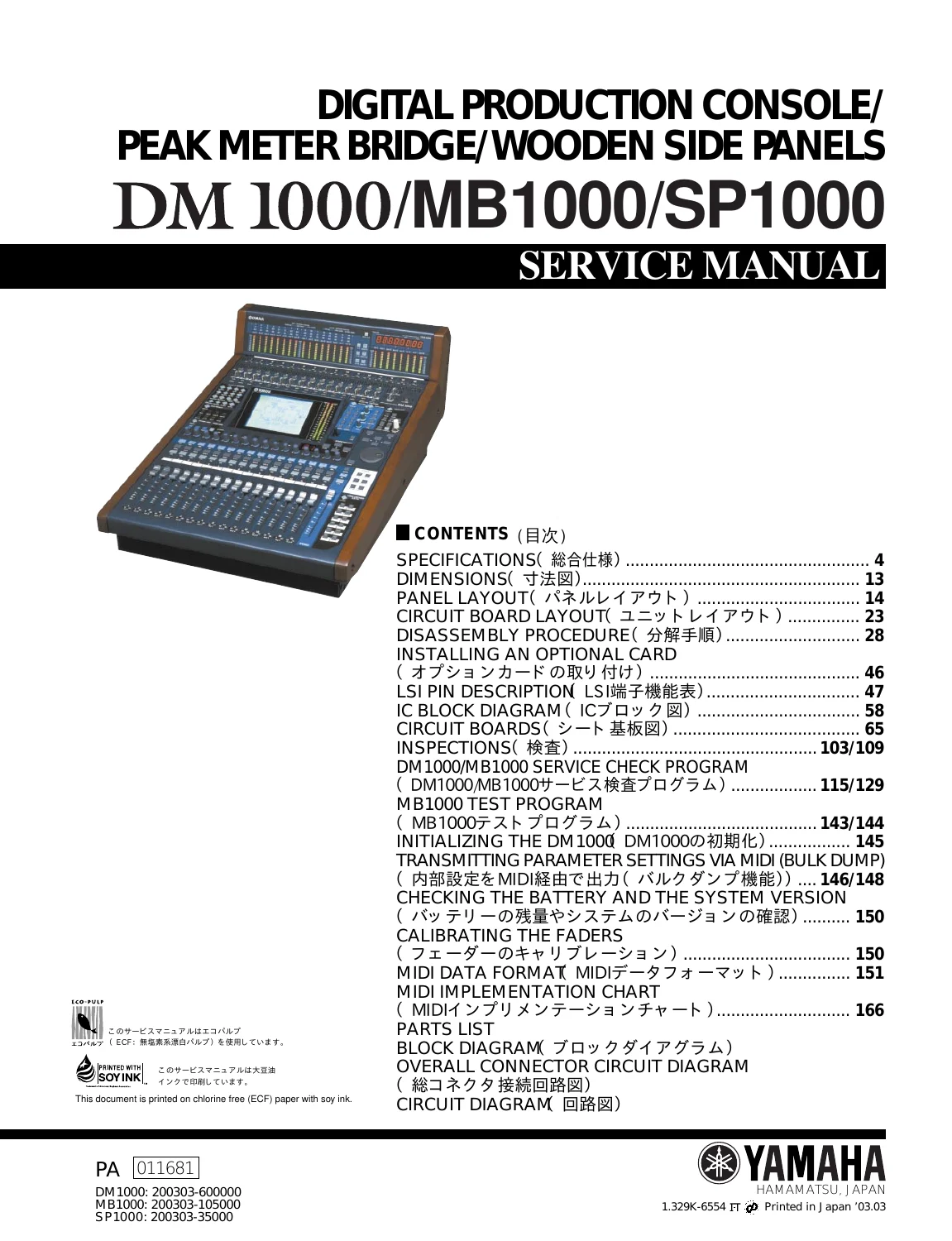
Yamaha DM1000 Digital Production Console, MB1000 Peak Meter Bridge & SP1000 Side Panels Service Manual
Original price was: $39.95.$24.95Current price is: $24.95.
Official factory service manual for the Yamaha DM1000 Digital Production Console, MB1000 Peak Meter Bridge, and SP1000 Wooden Side Panels. Features full schematic circuit diagrams, block diagrams, PCB foil layouts, disassembly guides, LSI pinouts, automated diagnostic test routines, fader calibration, and complete parts lists.
Description
Yamaha DM1000 Digital Production Console, MB1000 Peak Meter Bridge & SP1000 Side Panels Service Manual
This technical publication is the original factory service documentation for the Yamaha DM1000 Digital Production Console, the companion MB1000 Peak Meter Bridge, and SP1000 Wooden Side Panels. Designed specifically for professional audio technicians, service centers, and recording studio engineers, this manual delivers comprehensive electronic diagnostic procedures, component-level schematic circuit diagrams, printed circuit board foil traces, modular disassembly guides, automated service check software routines, and exhaustive mechanical and electrical parts listings.
Document Details & Technical Specifications
- Document Type: Factory Service Manual / Technical Reference Manual
- Applicable Equipment: Yamaha DM1000 Digital Production Console, MB1000 Peak Meter Bridge, SP1000 Wooden Side Panels
- Publication Part Number: PA 011681 / 1.329K-6554
- Publication Date & Release: March 2003 (Printed in Japan ‘03.03)
- Reference Serial Numbers: DM1000: 200303-600000, MB1000: 200303-105000, SP1000: 200303-35000
- Total Page Count: 307 pages
- Language: English (with Japanese supplementary technical labels)
- File Format: Portable Document Format (PDF)
Chapters & Technical Content Covered
Specifications
- General performance specifications (99 scene memories, internal/external sampling rates from 44.1 kHz to 96 kHz, sub-1.6 ms latency at 48 kHz and sub-0.8 ms at 96 kHz, 100 mm touch-sensitive motorized faders with 1024-step resolution, THD, dynamic range, equivalent input noise -128 dB)
- 4-band parametric EQ curves
- Gate/Ducking dynamics parameters
- Compressor/Expander/Compander parameters
- Internal effects libraries
- Preset memory tables
- Analog input/output sensitivity levels (+4 dB nominal / +24 dB clipping)
- Digital AES/EBU and IEC-60958 I/O ratings
- Mini-YGDAI slot compatibility (MY16, MY8, MY4, mLAN, Waves Y56K, Apogee AP8 series)
- Time code sync
- Control I/O specs
Dimensions
Detailed dimensional blueprints and chassis mechanical drawings for standalone DM1000 units and complete console setups configured with the MB1000 meter bridge and SP1000 side panels.
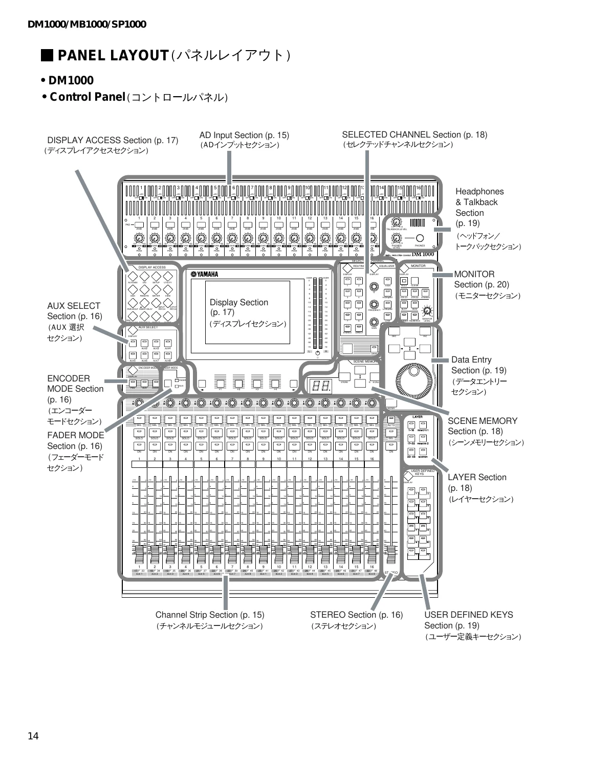
Panel Layout
- Complete control surface mapping covering the AD Input section (+48V phantom power switches, 20 dB pads, rotary gain controls, peak/signal LEDs)
- Channel Strip section (rotary encoders, SEL, SOLO, and ON keys)
- STEREO master fader strip
- AUX SELECT array
- ENCODER MODE assign buttons
- FADER MODE routing keys
- DISPLAY ACCESS matrix (Automix, DIO, Setup, Utility, MIDI, Remote, Meter, View, Pair/Group, Insert/Delay, Input/Output Patch, Pan/Surround, Dynamics, Effect, Scene)
- LCD Display module
- SELECTED CHANNEL equalizer and bus routing controls
- LAYER selectors (1-16, 17-32, 33-48, Remote 1/2, Master)
- SCENE MEMORY numeric display and recall buttons
- USER DEFINED KEYS (1-12)
- Data Entry parameter wheel
- Talkback/Headphones panel
- MONITOR control section
- MB1000 meter bridge LED bar graph arrays
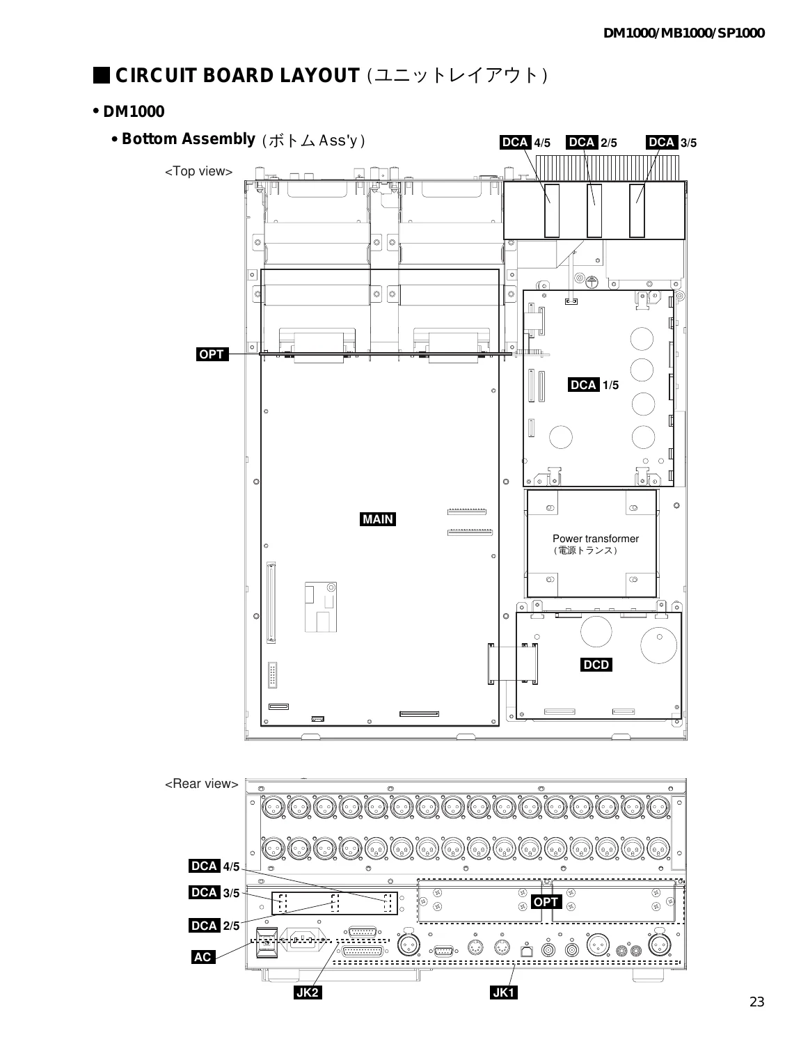
Circuit Board Layout
Spatial PCB arrangement and internal interconnection schematics for the DM1000 bottom assembly (MAIN, DCA 1/5 through 4/5, DCD, OPT, JK1, JK2, power transformer), rear assembly U (HAAD 1/2, HAAD 2/2, ADA, XLR), control panel assembly (FD fader board, PN1 1/4 through 4/4, PN2, LCD inverter board), and MB1000 front/rear panel assemblies.
Disassembly Procedure
Step-by-step mechanical disassembly instructions with torque sequences, fastener dimensions, and technician service time estimates for removing side panels, meter bridge, top control surface, rear I/O chassis, DCD board, DCA power distribution boards, OPT slot interface, MAIN digital processing board, CR2032 lithium backup battery replacement, JK1/JK2 jack boards, AC line filter and inlet, heat sinks, preamplifier boards, motorized fader carriage assembly, LCD screen, panel switch matrix PCBs, and rotary encoder modules.
Installing an Optional Card
Proper ESD handling, physical installation guidelines, guide rail insertion, and grounding precautions for mini-YGDAI digital I/O expansion cards in Slots 1 and 2.
LSI Pin Description
- M37641M8-141FP (USB CPU)
- HD6417709SF133 (SH-3 Main CPU)
- SH7042 (SUB CPU)
- MBCG46183-129PFV-G (SIO4 Gate Array)
- SGH603064F-62F (Encoder Gate Array)
- YSS910-S (DSP6 Digital Signal Processor)
- YSS919B-H (DSP7 Digital Signal Processor)
- MBCG61594-130 (ATSC2A Audio Timing / Routing Controller)
- YM3436DK (DIR2 Digital Format Interface Receiver)
- CS8405A-CS (DIT Digital Audio Transmitter)
- S1D13704F00A100 (LCD Controller)
- CS8420 (Sample Rate Converter)
- ICS2008BV-T (SMPTE Time Code Reader/Generator)
- AK4393-VF-E2 (24-bit 96 kHz DAC)
- CS5361-KS (24-bit 96 kHz ADC)
- MB1000 SH7042 CPU
IC Block Diagrams
Internal logic schematics and pin diagrams for digital gates, multi-channel multiplexers/demultiplexers, line transceivers, bus drivers, flip-flops, operational amplifiers, comparator circuits, and voltage regulators.
Circuit Boards
Component-side and solder-side PCB layout diagrams illustrating all surface-mount and through-hole test points, connector assignments, component designations, and circuit traces across all console assemblies (MAIN, DCA, DCD, FD, HAAD, ADA, JKCOM, PNCOM, XLR, and MB1000).
Inspections & Alignment
- Workshop test specifications for analog I/O frequency response, residual noise floors (-86 dBu), total harmonic distortion (under 0.01%), inter-channel crosstalk
- Phantom power output (+48V DC verification)
- Digital I/O signal integrity at 44.1/48/88.2/96 kHz
- Word clock PLL tracking limits
- Jitter measurements (under 5 ns internal, under 10 ns external)
- Listening evaluation procedures
- Firmware updating via USB/Flash Update utility
- Memory initialization
DM1000 / MB1000 Service Check Program
Built-in automated diagnostic routines detailing menu navigation, PLL lock tests, battery voltage A/D measurements (certified 2.80V to 3.50V), DSP6/DSP7 memory and SIO communications bus testing, MIDI loopback transmission, 2TR digital I/O loop tests, LCD visual test patterns, panel switch and LED matrix validation, motorized fader touch sense calibration and travel verification, rotary encoder tracking, and interactive audio routing check mode.
MB1000 Test Program
Stand-alone test routines for the peak meter bridge, including communications loopback, LED color sweeps (red, green, orange), channel level bar graph sequences, and SMPTE time code display verification.
IMAGES PREVIEW
Console Initialization & Fader Calibration
Procedures for restoring factory default presets, resetting the security lock password, running automated motorized fader calibration routines, and executing full parameter bulk dumps via MIDI.
MIDI Data Format & Implementation
Complete MIDI system exclusive parameter change specifications, bulk dump formatting for scene memories, setup data, channel libraries, EQ/compressor/gate libraries, and remote control implementation tables.
Parts List & Schematic Circuit Diagrams
Fully exploded mechanical drawings, electrical parts lists with Yamaha part numbers, master block diagram, overall connector wiring schematics, and full-resolution circuit schematics for all audio and digital PCB modules.
Professional Repair, Calibration & Troubleshooting Capabilities
Whether you are rebuilding the analog input stages, troubleshooting sample rate clocking faults, replacing worn motorized faders, updating system firmware, or tracing circuit board signals on the Yamaha DM1000 Digital Production Console, MB1000 Peak Meter Bridge & SP1000 Side Panels Service Manual, having the complete manufacturer service guide is critical. Exact component reference numbers, digital bus logic diagrams, and automated diagnostic sequences allow you to repair and maintain equipment with studio-grade reliability.
Instant Access & Digital Delivery
This comprehensive service manual is available as an instant digital PDF download immediately upon checkout. You can easily view the high-resolution circuit diagrams and assembly drawings on desktop computers, laptops, or workshop tablets, or print out specific schematic diagrams and disassembly steps for direct benchtop reference.
Reviews
There are no reviews yet.