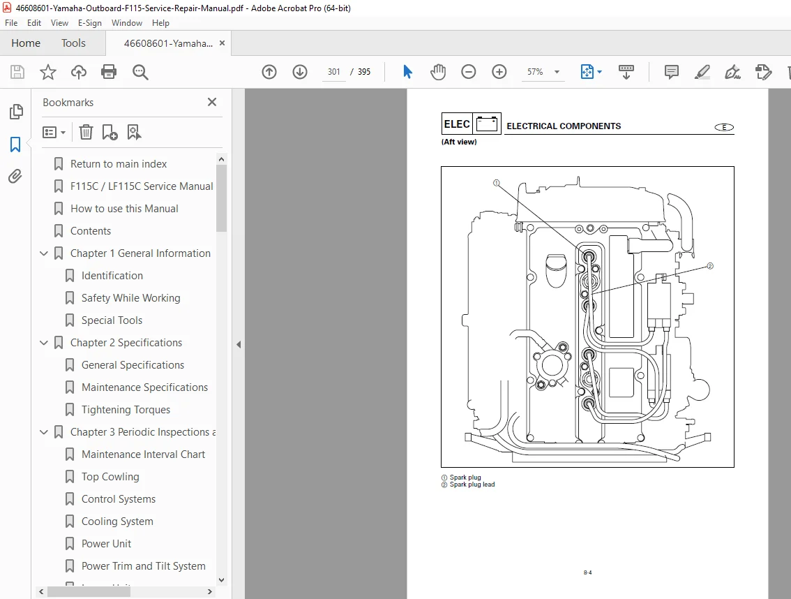
Yamaha F115C LF115C Outboard Service Manual PDF
Original price was: $85.00.$28.95Current price is: $28.95.
Complete 395-page factory service manual for Yamaha F115C/LF115C 115 horsepower 4-stroke outboard motors. Comprehensive guide covering specifications, periodic inspections, fuel system, power unit, lower unit, bracket unit, electrical systems, troubleshooting, complete disassembly/assembly procedures, exploded views, and parts lists for professional marine technicians.
Description
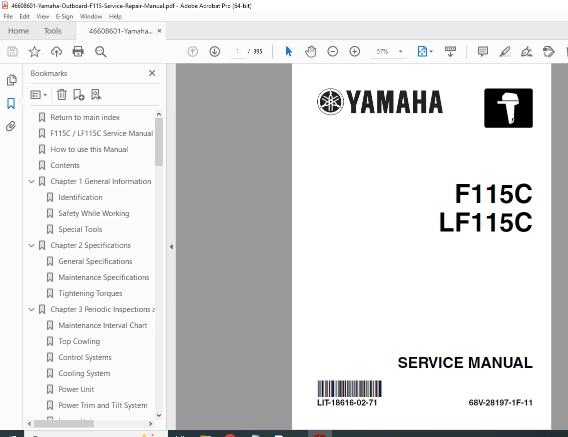
Yamaha F115C LF115C Outboard Service Manual 115HP 4-Stroke Motor Repair – PDF DOWNLOAD
DESCRIPTION:
This comprehensive Yamaha F115C/LF115C Service Manual provides complete factory technical documentation for servicing and repairing Yamaha 115 horsepower 4-stroke outboard motors. This massive 395-page professional manual is essential for marine mechanics, boat repair shops, Yamaha dealers, and professional technicians working on these popular mid-range outboard engines.
Models Covered
This factory service manual covers all variants of the Yamaha 115 HP 4-stroke outboard series:
Standard Shaft Models:
- F115C – Standard 20-inch shaft model (International)
- F115AET / F115TR – USA and Canada designation
Long Shaft Models:
- LF115C – Long 25-inch shaft model (International)
- FL115AET / LF115TR – USA and Canada designation
All models feature the same 4-stroke, 4-cylinder in-line engine with identical service procedures and specifications.
Engine Specifications
General Specifications:
- Engine type: 4-stroke, 4-cylinder in-line
- Power output: 115 horsepower
- Displacement: Inline 4-cylinder configuration
- Fuel system: Electronic fuel injection (EFI)
- Cooling system: Water-cooled with thermostat
- Ignition system: Electronic ignition
- Starting system: Electric start
- Alternator: Charging system for battery maintenance
- Transom height: Standard (20″) or Long (25″)
- Tilt system: Power trim and tilt
- Gear ratio: Forward, Neutral, Reverse
Key Features:
- 4-stroke technology for quiet operation and fuel efficiency
- Electronic fuel injection for smooth performance
- Power trim and tilt for optimal boat handling
- Freshwater flushing system for saltwater use
- Anti-cavitation plate design
- Multiple mounting options
Complete Manual Contents
Chapter 1: GENERAL INFORMATION
- Identification:
- Serial number location and reading
- Model name identification
- Approved model code
- Transom height designation
- Starting serial numbers for production runs
- Safety While Working:
- Fire prevention protocols
- Proper ventilation requirements
- Self-protection equipment and procedures
- Oils, greases, and sealing fluids specifications
- Good working practices
- Disassembly and assembly guidelines
- Special Tools:
- Measuring tools and specifications
- Specialized removal and installation tools
- Tool part numbers and descriptions
- Improvised tool alternatives
- Features and Advantages:
- 4-stroke technology benefits
- Fuel efficiency features
- Environmental advantages
- Performance characteristics
- Location of Main Components:
- External component identification
- Internal component locations
- Service access points
- Model Identification and Serial Numbers:
- Serial number plate location
- Model code interpretation
- Production date coding
- Engine Mounting:
- Mounting height specifications
- Transom requirements
- Test running procedures
- Transom elevators usage
- Anti-cavitation plate positioning
- Operating Instructions:
- Shifting procedures and precautions
- Remote control operation
- Steering system usage
- Shallow water operation guidelines
- Intake blockage prevention
- Mooring procedures
- Throttle use best practices
- Tilt and trim operation
- Maintenance, Lubrication, and Storage:
- General maintenance schedule
- Bearing lubrication procedures
- Impeller clearance setting
- Linkage adjustment procedures
- Salt water operation special requirements
- Proper storage procedures
Chapter 2: SPECIFICATIONS
- General Specifications:
- Engine type and configuration
- Number of cylinders (4)
- Displacement specifications
- Bore and stroke measurements
- Compression ratio
- Maximum horsepower output
- Operating RPM range
- Fuel type requirements
- Oil capacity and specifications
- Electrical system specifications
- Weight specifications
- Dimension specifications
- Maintenance Specifications:
- Cylinder Heads:
- Valve specifications
- Valve spring specifications
- Valve guide specifications
- Valve seat specifications
- Camshaft specifications
- Cylinders:
- Cylinder bore specifications
- Piston-to-cylinder clearance
- Piston ring specifications
- Ring end gap specifications
- Valve Train:
- Valve lifter-to-cylinder-head clearance
- Rocker arm specifications
- Valve timing specifications
- Cylinder Head Assembly:
- Cylinder head cover torque specifications
- Head bolt tightening sequence and torque
- Gasket specifications
- Lubrication System:
- Oil pump specifications
- Oil pressure specifications
- Oil filter specifications
- Fuel System:
- Fuel pump pressure specifications
- Injector specifications
- Throttle body specifications
- Cooling System:
- Water pump specifications
- Thermostat opening temperature
- Impeller specifications
- Ignition System:
- Spark plug type and gap
- Ignition timing specifications
- CDI unit specifications
- Electrical System:
- Battery specifications
- Charging voltage specifications
- Starter motor specifications
- Lower Unit:
- Gear oil capacity
- Propeller shaft specifications
- Gear ratio specifications
- Tightening Torque Specifications:
- Standard bolt/nut torque chart by thread pitch
- Special component torque specifications
- Sequential tightening procedures
- Cylinder Heads:
Chapter 3: PERIODIC INSPECTIONS AND ADJUSTMENTS
- Pre-Operation Inspections:
- Visual inspection checklist
- Fluid level checks
- Control linkage verification
- Safety equipment check
- Periodic Maintenance Schedule:
- Initial break-in service
- 20-hour service
- 100-hour service
- Annual service
- Extended storage service
- Inspection Procedures:
- Fuel system inspection
- Cooling system inspection
- Electrical system inspection
- Lower unit inspection
- Propeller inspection
- Anodes inspection and replacement
- Adjustment Procedures:
- Shift Cam Assembly with Neutral Adjustment:
- Procedure for all models
- Linkage synchronization
- Verification testing
- Neutral Adjustment:
- Shift linkage adjustment
- Control cable adjustment
- Remote control synchronization
- Trim Adjustment:
- Trim angle settings
- Trim limit adjustments
- Idle Speed Adjustment:
- Warm-up procedures
- Idle RPM setting
- Idle quality verification
- Performance Tips:
- Propeller selection
- Trim optimization
- Fuel system maintenance
- Shift Cam Assembly with Neutral Adjustment:
- Lubrication Points:
- Grease points location and schedule
- Lubrication specifications
- Special lubrication procedures
Chapter 4: FUEL SYSTEM
- Fuel System Overview:
- System description and operation
- Component location diagrams
- Fuel flow schematics
- Component Service:
- Fuel Tank and Lines:
- Tank inspection
- Fuel line replacement
- Fuel filter service
- Fuel Pump:
- Removal and installation
- Testing procedures
- Pressure specifications
- Troubleshooting
- Fuel Injectors:
- Removal and installation
- Cleaning procedures
- Testing specifications
- Flow rate verification
- Throttle Body:
- Disassembly and assembly
- Cleaning procedures
- Position sensor testing
- Idle speed control
- High-Pressure Fuel Line:
- Inspection procedures
- Pressure testing
- Replacement procedures
- Fuel Rail:
- Service procedures
- Pressure regulator testing
- Fuel Tank and Lines:
- Troubleshooting:
- Hard starting diagnosis
- Poor acceleration diagnosis
- Rough idle diagnosis
- Fuel system pressure testing
Chapter 5: POWER UNIT
- Engine Removal and Installation:
- Powerhead removal procedures
- Mounting alignment
- Installation torque specifications
- Cylinder Head Service:
- Cylinder Head Cover Removal:
- Bolt sequence
- Gasket inspection
- Cylinder Head Removal:
- Bolt loosening sequence
- Warpage inspection
- Resurfacing specifications
- Valve Service:
- Valve removal and installation
- Valve guide replacement
- Valve seat machining
- Valve lapping procedures
- Valve spring testing
- Camshaft Service:
- Removal and installation
- Bearing inspection
- Lobe wear measurement
- Timing chain service
- Cylinder Head Installation:
- Gasket installation
- Bolt tightening sequence
- Torque specifications
- Valve clearance adjustment
- Cylinder Head Cover Removal:
- Cylinder and Piston Service:
- Piston Removal:
- Connecting rod removal
- Piston pin removal
- Cylinder Inspection:
- Bore measurement
- Out-of-round measurement
- Taper measurement
- Honing procedures
- Piston Inspection:
- Piston-to-cylinder clearance
- Ring groove wear
- Piston ring installation
- Ring end gap measurement
- Piston Installation:
- Ring orientation
- Installation procedures
- Connecting rod installation
- Piston Removal:
- Crankshaft and Crankcase:
- Crankcase Disassembly:
- Case separation procedures
- Bearing removal
- Crankshaft Inspection:
- Runout measurement
- Journal measurement
- Oil clearance specifications
- Bearing Service:
- Bearing inspection criteria
- Installation procedures
- Clearance verification
- Crankcase Assembly:
- Sealant application
- Case mating procedures
- Bolt tightening sequence
- Crankcase Disassembly:
- Oil Pump Service:
- Removal and installation
- Disassembly and inspection
- Pressure testing
- Clearance specifications
- Timing Chain Service:
- Chain inspection
- Tensioner service
- Timing mark alignment
- Exploded Views:
- Complete powerhead assembly
- Cylinder head assembly
- Piston and connecting rod assembly
- Crankshaft assembly
- Oil pump assembly
Chapter 6: LOWER UNIT
- Lower Unit Overview:
- Design and operation
- Component identification
- Oil capacity and type
- Lower Unit Removal and Installation:
- Water pump inspection access
- Complete lower unit removal
- Installation procedures
- Alignment verification
- Propeller Service:
- Propeller removal and installation
- Propeller inspection criteria
- Propeller shaft seal replacement
- Spline inspection
- Water Pump Service:
- Impeller replacement
- Housing inspection
- Clearance adjustment
- Plate and seal replacement
- Gear Case Service:
- Disassembly:
- Sequential disassembly procedures
- Component identification
- Inspection:
- Gear tooth pattern
- Bearing inspection
- Shaft runout measurement
- Gear backlash measurement
- Assembly:
- Bearing installation
- Shim selection
- Backlash adjustment
- Preload adjustment
- Sealant application
- Disassembly:
- Shift System Service:
- Shift shaft removal
- Dog clutch inspection
- Shift cam service
- Detent ball and spring
- Drive Shaft:
- Removal and installation
- Spline inspection
- Bearing service
- Exploded Views:
- Complete lower unit assembly
- Gear case assembly
- Water pump assembly
- Propeller assembly
Chapter 7: BRACKET UNIT
- Clamp Bracket:
- Removal and installation
- Transom pad inspection
- Clamp screw service
- Swivel Bracket:
- Pivot point service
- Bushing replacement
- Grease points
- Tilt/Trim System:
- Power Trim and Tilt:
- Hydraulic system operation
- Fluid specifications
- Bleeding procedures
- Tilt/Trim Unit Service:
- Removal and installation
- Disassembly procedures
- Seal replacement
- Cylinder inspection
- Pump motor testing
- Manual Tilt System:
- Tilt lock mechanism
- Adjustment procedures
- Power Trim and Tilt:
- Steering System:
- Steering tube service
- Friction adjustment
- Cable connection
- Anodes:
- Anode locations
- Inspection criteria
- Replacement procedures
- Exploded Views:
- Bracket assembly
- Tilt/trim unit
- Steering components
Chapter 8: ELECTRICAL SYSTEMS
- Electrical System Overview:
- System description
- Wiring color codes
- Circuit protection
- Battery and Charging:
- Battery specifications
- Charging system operation
- Alternator testing
- Voltage regulator testing
- Starting System:
- Starter motor service
- Solenoid testing
- Starting circuit diagnosis
- Ignition System:
- CDI unit operation
- Spark plug service and specifications
- Ignition coil testing
- Pickup coil testing
- Timing verification
- Fuel Injection System Electronics:
- ECU operation
- Sensor testing procedures
- Throttle position sensor
- Manifold absolute pressure sensor
- Engine temperature sensors
- Oxygen sensor (if equipped)
- Instrumentation:
- Gauge testing
- Sender unit service
- Warning systems
- Wiring Diagrams:
- Complete system wiring diagram
- Starting circuit
- Charging circuit
- Ignition circuit
- Fuel injection circuit
- Instrumentation circuit
- Connector identification and pinouts
- Electrical Troubleshooting:
- Systematic diagnosis procedures
- Voltage and resistance testing
- Component testing specifications
Chapter 9: TROUBLE ANALYSIS
- Troubleshooting Guide:
- Engine Will Not Start:
- Fuel system checks
- Ignition system checks
- Compression testing
- Starter system checks
- Engine Runs Rough:
- Idle quality issues
- Fuel delivery problems
- Ignition problems
- Compression loss
- Poor Performance:
- Acceleration problems
- Maximum speed issues
- Fuel economy problems
- Overheating:
- Cooling system diagnosis
- Water pump inspection
- Thermostat testing
- Blockage identification
- Abnormal Noise:
- Mechanical noise diagnosis
- Exhaust noise problems
- Gear noise diagnosis
- Electrical Problems:
- Charging system diagnosis
- Starting problems
- Gauge malfunctions
- Lower Unit Problems:
- Shifting difficulties
- Propeller cavitation
- Gear noise
- Oil leaks
- Engine Will Not Start:
- Diagnostic Procedures:
- Compression testing
- Vacuum pressure testing (all cylinders)
- Fuel pressure testing
- Electrical system testing
- Lower unit pressure testing
- Special Service Procedures:
- Break-in procedures for new/rebuilt engines
- Valve clearance checking and adjustment
- Carburetor synchronization (if applicable)
- Remote control cable adjustment
Parts Lists and Exploded Views:
- Complete illustrated parts breakdown
- Assembly instructions with numbered sequences
- Symbols indicating:
- Apply grease
- Apply oil
- Apply sealant
- Replace part
- Torque specifications
- Special tools required
- Job instruction charts with:
- Part names and quantities
- O-ring sizes (inside diameter × ring diameter)
- Bolt/screw sizes (diameter × length)
- Dimensional specifications
- Important points for each procedure
Key Features of This Service Manual
✓ Massive 395-page manual – Most comprehensive coverage available ✓ Official Yamaha factory documentation – Authorized service information ✓ Complete coverage of F115C/LF115C 115 HP 4-stroke outboards ✓ Detailed exploded views – Numbered sequences for all procedures ✓ Job instruction charts – Step-by-step with specifications ✓ Torque specifications – Complete charts for all fasteners ✓ Electrical wiring diagrams – Full system schematics with color codes ✓ Troubleshooting guide – Systematic diagnostic procedures ✓ Special tools identified – With part numbers and alternatives ✓ Both USA and international models – Complete model coverage ✓ Periodic maintenance schedules – Hour-based service intervals ✓ Sequential procedures – Step-by-step for all repairs
Who Should Use This Manual
This Yamaha F115C/LF115C service manual is designed for:
- Professional marine mechanics
- Yamaha authorized dealers and service centers
- Boat repair facilities
- Marina service departments
- Marine technical schools
- Experienced boat owners with mechanical knowledge
- Fleet maintenance operations
Important Service Information
Manual Usage:
- Written for trained mechanics with basic mechanical and electrical knowledge
- Sequential step-by-step format throughout
- Illustrations represent all designated models
- Cross-references kept to minimum for easy navigation
Safety Information:
WARNING – Severe injury or death possible:
- Follow all WARNING instructions
- Machine operator, bystander, and service personnel safety
CAUTION – Equipment damage possible:
- Special precautions to avoid motor damage
- Proper procedures must be followed
NOTE – Key information:
- Makes procedures easier or clearer
- Important reference points
Service Strategy:
- Test and verify before replacing parts
- Reinstall original if replacement doesn’t solve problem
- Replace only defective components
- Note BIOS/ECU configurations before service
- Single failures may not indicate hard failure
Model Designations:
- F115AET (International) = F115TR (USA/Canada)
- FL115AET (International) = LF115TR (USA/Canada)
- LF prefix indicates Long shaft version
Serial Number Location:
- Stamped on label on port clamp bracket
- Contains: Model name, Approved model code, Transom height, Serial number
Continuous Improvement:
- Yamaha policy of continuous product improvement
- Models may differ from illustrations
- Use latest edition of manual
- Check for updates and technical bulletins
Maintenance Highlights
- Oil and filter changes per schedule
- Spark plug inspection and replacement
- Fuel system cleaning and inspection
- Water pump impeller replacement intervals
- Lower unit gear oil changes
- Anode inspection and replacement
- Valve clearance checking (if applicable)
- Propeller inspection and service
- Cooling system flushing (especially saltwater use)
- Electrical connections cleaning and protection
Manual Quality and Format
- Format: Professional PDF document optimized for viewing
- Pages: 395 pages of comprehensive technical content
- Graphics: High-quality exploded views, photographs, diagrams
- Organization: Logical chapter structure with detailed contents
- File size: 13.0 MB – Extensive illustrations and schematics
- Publisher: Yamaha Motor Corporation, USA – Official factory documentation
- Print-friendly: A4 page size suitable for workshop use
This Yamaha F115C/LF115C Service Manual PDF provides complete factory technical documentation essential for professional service, repair, and maintenance of these popular 115 horsepower 4-stroke outboard motors used worldwide on a wide variety of boats.
FILE DETAILS:
| Manual Type | Factory Service Manual |
|---|---|
| Models Covered | F115C (Standard shaft)<br>LF115C (Long shaft)<br>F115AET / F115TR (USA/Canada)<br>FL115AET / LF115TR (USA/Canada) |
| Engine Type | 4-Stroke, 4-Cylinder |
| Horsepower | 115 HP |
| Year | 2003 Edition (October 2003, Updated 2004) |
| Pages | 395 pages |
| PDF Quality | Excellent – Original manufacturer document |
| File Size | 13.0 MB |
| Language | English |
| Publisher | Yamaha Motor Corporation, USA / YMC, Ltd. |
| Manual Number | LIT-18616-02-71 / 68V-28197-1F-11 |