
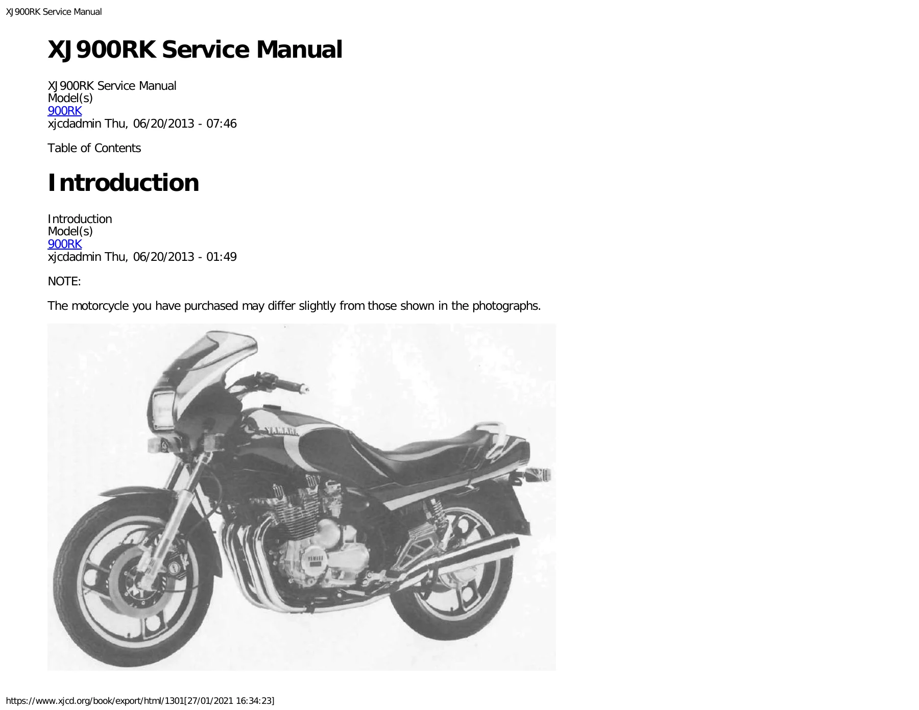
Yamaha XJ900RK Service Manual – Complete 900RK Workshop Repair Guide PDF
Original price was: $34.95.$20.95Current price is: $20.95.
The full 312-page Yamaha XJ900RK Service Manual for the 900RK model. Covers engine overhaul, DOHC cylinder head and valve service, carburetor synchronization, shaft drive and middle gear, front forks and anti-dive, brakes, electrical and T.C.I. ignition, specifications, and exploded diagrams. Instant PDF download.
Description
Yamaha XJ900RK Service Manual – Complete 900RK Workshop Repair Guide PDF
This is the complete Yamaha XJ900RK Service Manual, the workshop repair guide written specifically for the 900RK model. It covers the entire motorcycle in one document – engine, transmission, shaft drive, chassis, brakes, suspension, carburetion, and electrical system – and provides the specifications, tightening torques, service limits, and step-by-step procedures needed to service, overhaul, or restore an XJ900RK. Whether you are adjusting valve clearance on a running bike or tearing the engine down to the crankcase, this Yamaha 900RK service manual gives you the numbers and sequences to do it correctly.
File Details
- Manual type: Service / Workshop Manual
- Brand: Yamaha
- Model: XJ900RK (900RK)
- Model code number: 33F
- Language: English
- Page count: 312 pages
- File format: PDF
- Frame starting serial number: 33F-000101
- Engine starting serial number: 33F-000101
Chapters Covered in This XJ900RK Workshop Manual
- Chapter 1 – General Information: motorcycle identification, frame serial number location, engine serial number location, special tools for tune-up, engine service, chassis service, and shaft drive service
- Chapter 2 – Periodic Inspections: maintenance intervals and lubrication schedule, front brake adjustment, rear brake pedal position, rear brake adjustment, front and rear brake pad wear check, brake fluid level and replacement, brake light switch adjustment, clutch adjustment, handlebar vertical and horizontal adjustment, battery, spark plug, headlight bulb replacement and beam adjustment, fuse replacement, generator brush replacement, fuel petcock cleaning and disassembly, cable and pivot lubrication, steering head bearings, front fork air pressure and oil, rear shock absorber preload and damping, anti-dive adjustment, cam chain, ignition timing check, air filter cleaning, carburetor synchronization, idle speed adjustment, engine oil and filter replacement, final gear oil level and replacement, compression pressure measurement, valve clearance check and pad selection
- Chapter 3 – Engine Overhauling: engine removal, engine disassembly, pick-up coil, shifter, starter motor, A.C. generator rotor removal, clutch, oil pump, middle gear and crankcase disassembly, cylinder head, cylinder and piston, cylinder head disassembly, valve inspection and repair, valve guide and oil seal replacement, valve seat grinding and lapping, valve spring and lifter inspection, camshafts and cam chain, cam sprockets, cam chain dampers and tensioner, cylinder bore measurement, piston and piston rings, crankshaft run-out and main bearing oil clearance, bearing selection, oil pump and clutch inspection, transmission inspection, starter drives, crankcases and strainer cover, middle gear damper service, engine assembly and adjustment, upper crankcase assembly, transmission, clutch and middle gear installation, shifter, generator, starter and pickup coils, pistons, cylinder and head installation, cam chain and cam sprocket timing, middle gear servicing and gear lash adjustment, reinstalling engine
- Chapter 4 – Carburetor and Air Cleaner: carburetor construction and disassembly, float chamber, main and pilot jets, vacuum piston and diaphragm, starter plunger, carburetor assembly alignment, fuel level adjustment, float height, air cleaner and crankcase ventilation system
- Chapter 5 – Chassis: front wheel removal and installation, front axle inspection, tubeless tires and aluminum wheels, front wheel inspection and wheel bearing replacement, rear wheel removal and installation, rear axle inspection, rear wheel inspection, brake caliper pad replacement, caliper disassembly, master cylinder disassembly, brake inspection and repair, brake disc installation, air bleeding, tires and tire pressure, front fork removal, disassembly, inspection and reassembly, anti-dive system removal, inspection and assembly, steering head adjustment, removal, inspection and reassembly, swing arm adjustment and removal, rear shock absorber (De Carbon system) handling notes and removal, cable and fittings, shaft drive troubleshooting, final gear removal and adjustment, gear lash check, final gear disassembly and reassembly, drive shaft and universal joint
- Chapter 6 – Electrical: electrical components, wiring diagrams for models with and without sidestand switch, electric starting system, starter motor inspection, starter relay, starting-circuit cut-off relay, neutral switch, diode, clutch switch, charging system, A.C. generator, voltage regulator, silicon rectifier, ignition system (T.C.I. – Transistor Control Ignition), ignition coil, pick-up coil, spark plug, lighting system tests, signal system tests, self-cancelling flasher system, sensors and switches, fuel sender unit, oil level switch, tachometer, digital clock, main switch, engine stop switch, lights switch, starter switch, dimmer switch, turn switch, horn switch, passing light switch, battery
- Chapter 7 – Specifications: general specifications, engine specifications, chassis specifications, electrical specifications, general torque specifications, unit definitions
- Chapter 8 – Exploded Diagrams: cylinder head, valve, cam chain, crankshaft and piston, oil cooler, clutch, transmission, middle gear and damper, final gear and drive shaft, front master cylinder, rear master cylinder, front brake caliper, rear brake caliper, front wheel, rear wheel, front fork, rear shock absorber, swing arm, lubrication diagrams, cable routing, speedometer and tachometer, electrical diagrams, wiring diagram
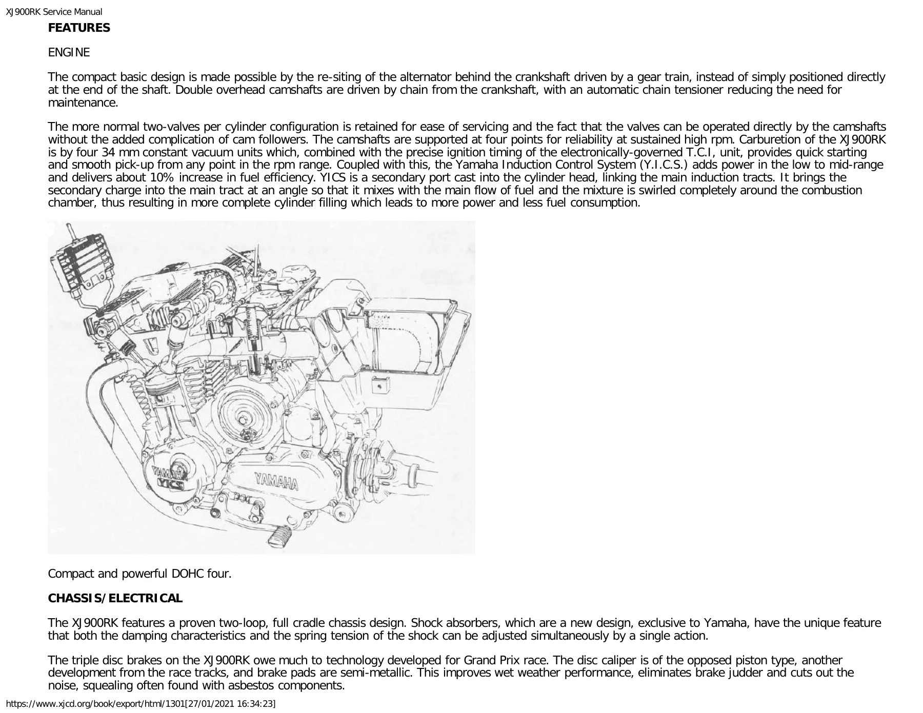
Across these eight chapters, the manual gives a technician the complete working picture of the XJ900RK: the DOHC air-cooled 853 cc inline-four with its gear-driven alternator, automatic cam chain tensioner, YICS (Yamaha Induction Control System) secondary port, four 34 mm constant-vacuum carburetors, electronically governed T.C.I. ignition, two-loop full cradle chassis, shaft final drive, air-assisted front fork with anti-dive, and the triple-disc brake system. Every procedure is supported by the service limits, torque values, clearances, and measurement points required to keep the machine within specification.
What This Yamaha XJ900RK Service Manual Enables You to Do
- Remove and completely strip the engine, including cylinder head, valves, pistons, crankshaft, and main bearings
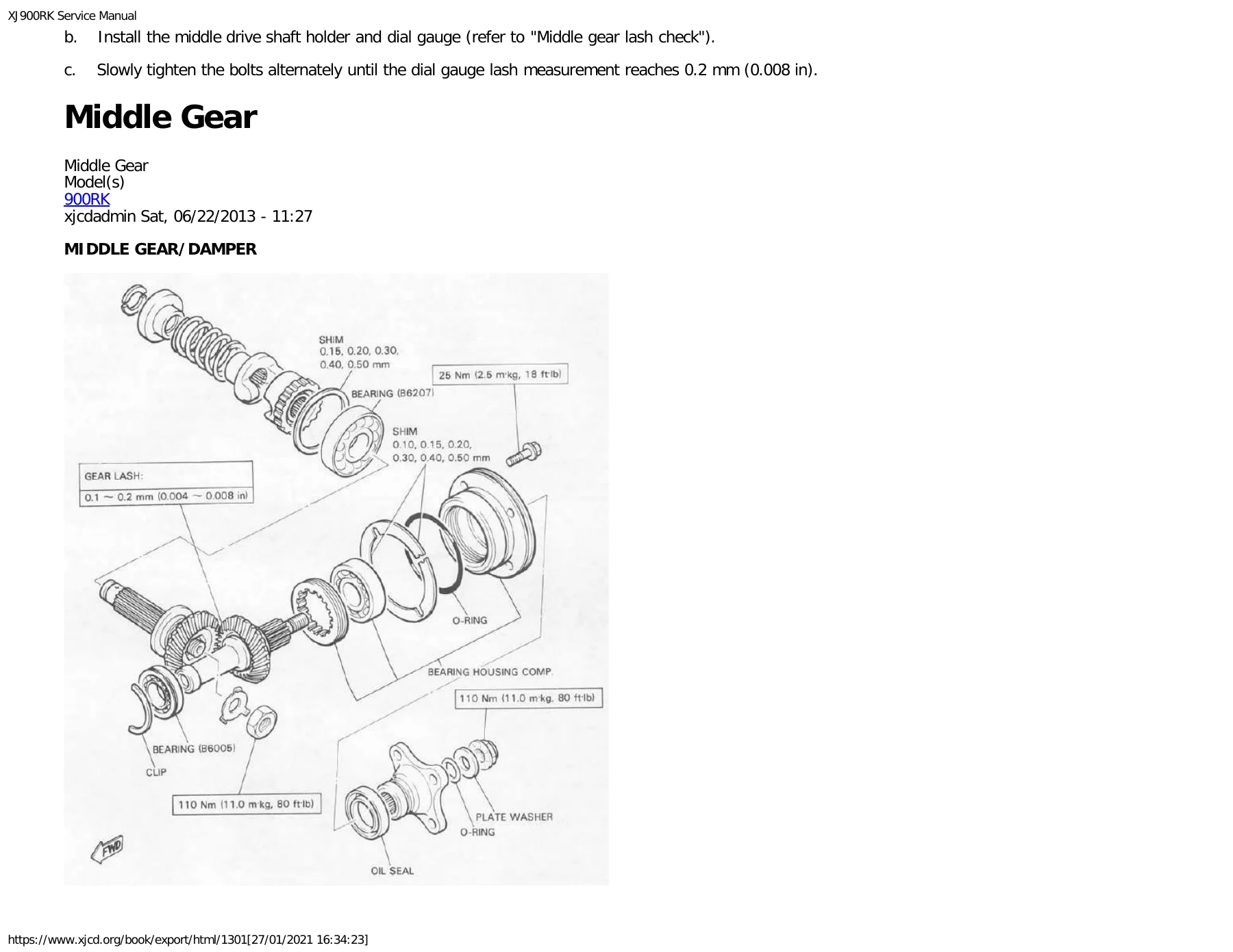
- Rebuild the clutch, transmission, and middle gear assembly with correct oil clearances and gear lash
- Set valve clearance using the adjusting pad selection charts and the alternate shim calculation method
- Synchronize all four carburetors, set fuel level, and set float height
- Service the shaft drive end to end – middle gear lash, final gear lash, drive shaft splines, and universal joint
- Overhaul the front forks, replace fork seals and bushes, set air pressure, and adjust the anti-dive units
- Rebuild front and rear brake calipers and master cylinders, replace pads, and bleed the system properly
- Diagnose the charging, starting, ignition, lighting, and signal systems using the wiring diagrams and component resistance values
- Look up tightening torques and service limits for engine, chassis, and drivetrain fasteners
- Reference exploded diagrams for correct parts orientation during assembly
- Perform the full periodic maintenance schedule with the correct intervals and procedures
The Yamaha XJ900RK Service Manual is the document to reach for when the work has to be done to specification rather than by feel. Valve clearances, camshaft-to-cap clearances, connecting rod oil clearances, main bearing oil clearances, middle gear lash, final gear lash, and every critical torque figure are spelled out – skipping them is exactly how engines, transmissions, and shaft drives get damaged. This 900RK workshop manual keeps those numbers in front of you at every step, from a simple oil change through a complete engine overhaul.
IMAGES PREVIEW
Delivered as an instant PDF download after payment. No shipping, no waiting. Read it on any device – desktop, laptop, tablet, or phone – and print the pages you need for the workshop bench. This Yamaha 900RK repair manual is the full 312-page document, not a partial excerpt or a scanned summary.


Reviews
There are no reviews yet.