
Yamaha YFM250XL Bear Tracker Service Manual 1998-2001 PDF
Original price was: $47.95.$29.95Current price is: $29.95.
Complete Yamaha YFM250XL Bear Tracker service manual covering the 1998 YFM250XLC plus the 2000 YFM250XN and 2001 YFM250XP. Full engine overhaul, carburetion, drive train, chassis, electrical and troubleshooting procedures with torque specs, service limits and exploded diagrams.
Description
Yamaha YFM250XL Bear Tracker Service Manual (1998-2001)
This is the full Yamaha service manual for the YFM250XL Bear Tracker family of 250-class ATVs, issued as the base 1998 edition and bundled together with the two factory supplementary manuals that extended coverage through the 2000 and 2001 model years. Every repair, rebuild, adjustment and diagnostic procedure that Yamaha published for these machines is inside one continuous PDF — from valve clearance shimming and cam chain timing to middle gear backlash, final drive shim selection and the complete wiring diagram.
File Details
- Manual type: Service Manual, with Supplementary Service Manuals for later model years
- Brand: Yamaha
- Models covered: YFM250XLC, YFM250XLC(C), YFM250XN, YFM250XP (Bear Tracker 250)
- Model codes: 4XE1 (USA), 4XE2 (CAL), 4XE3 (CDN), 4XEA (USA), 4XEE (USA)
- Language: English
- Page count: 398
- File format: PDF
- Document numbers: LIT-11616-12-01 (base), LIT-11616-14-17, LIT-11616-15-03
- Editions: First Edition, February 1998; Supplementary, April 2000; Supplementary, June 2001
Chapters Covered
- General Information
- Specifications
- Periodic Inspections and Adjustments
- Engine Overhaul
- Carburetion
- Drive Train
- Chassis
- Electrical
- Troubleshooting
General Information
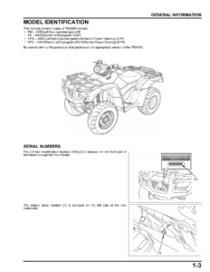
Machine identification (VIN and model label locations), preparation for removal procedures, replacement-part practice, gasket/seal/O-ring handling, lock washer and cotter pin discipline, bearing and oil seal installation, circlip orientation, connector and continuity checking, and the full special tool inventory. This is where the manual teaches its own conventions — the circled-number part references, torque boxes, wear-limit symbols and lubricant icons used on every later page — before you touch a fastener.
Specifications
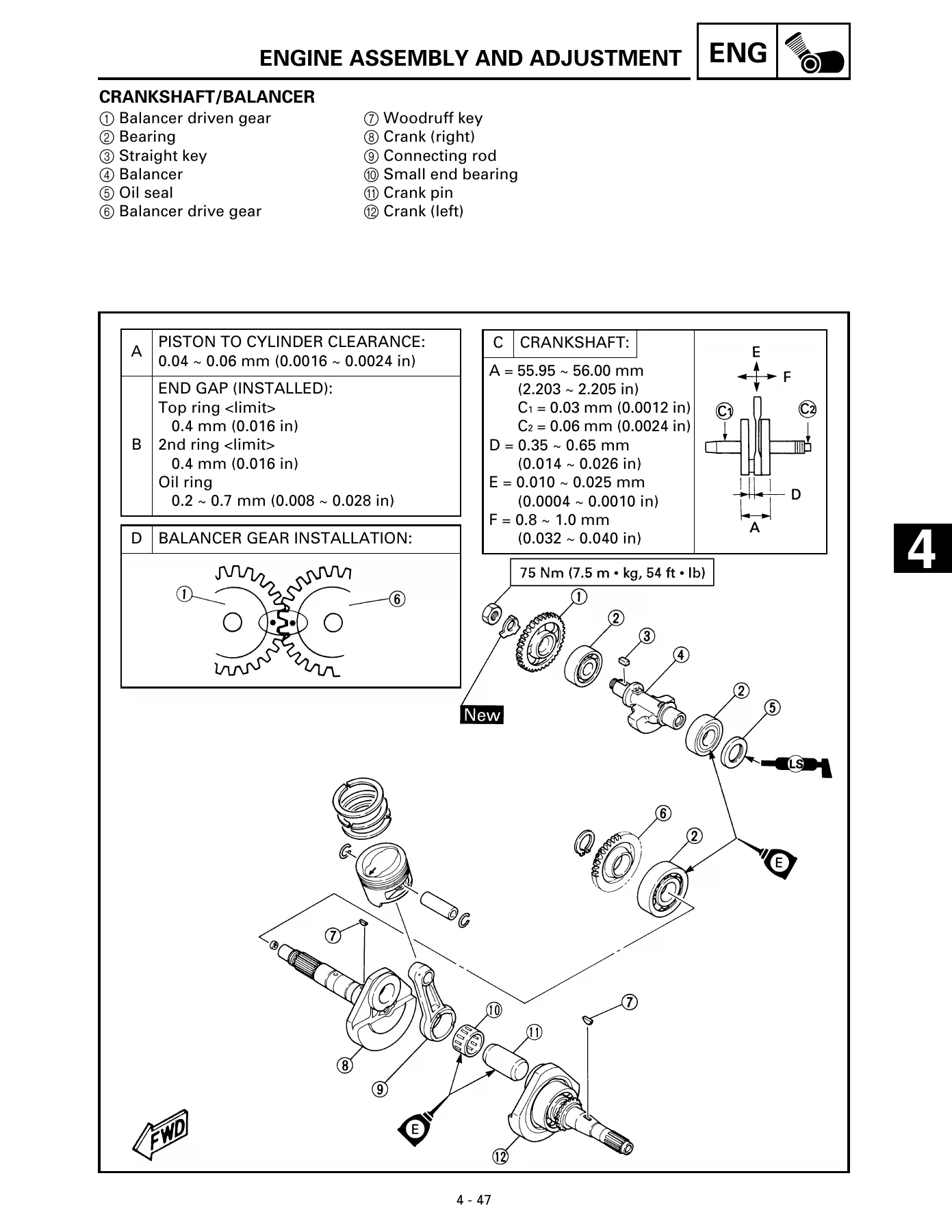
The complete factory spec set: general dimensions, basic weight, engine type and displacement, lubrication system and oil capacity, final gear oil type, fuel and carburetor data, clutch and transmission ratios, chassis geometry, tire sizes and pressures, brake and suspension values, and electrical ratings. Maintenance specifications follow with the standard/limit columns for cylinder head warp, cylinder bore, camshaft, valve clearance, valve springs, piston, rings, crankshaft, and the oil pump clearances. A conversion table, general torque specifications, lubrication point charts and the full tightening-torque tables for engine and chassis fasteners complete the chapter.
Periodic Inspections and Adjustments
Every scheduled maintenance task from the lubrication chart onward: fender and fuel tank removal, valve clearance adjustment with the Top Dead Center alignment procedure, timing chain tensioner check, idle speed and pilot screw setting, throttle cable free play, speed limiter adjustment, spark plug inspection and ignition timing check, compression pressure measurement, engine oil level and replacement, clutch release lever adjustment, air filter cleaning, front and rear brake lining inspection and adjustment, drive select lever position, final drive gear oil level and replacement, drive shaft dust boot inspection, steering system inspection, toe-in adjustment, shock absorber inspection and rear spring preload, tire and wheel inspection, plus battery, fuse and headlight beam service.
Engine Overhaul
The longest chapter: complete engine removal sequence, then disassembly into cylinder head assembly, cylinder and piston, starter pulley and CDI magneto, middle driven pinion gear, primary and secondary clutches, oil pump and shifter, balancer driven gear, crankcase separation, and balancer shaft/transmission/crankshaft extraction. Inspection and repair follows with tolerances and wear limits for the cylinder head, intake and exhaust valves, valve guides and seats (including the 30°/45°/60° cutter refacing and lapping steps), valve springs, camshaft lobes, rocker arms, timing chain and sprockets, tensioner, cylinder and piston, piston rings and pin, crankshaft, balancer gears, primary gears and starter clutch, clutches, oil pump, and transmission with shifter. Reassembly and adjustment is covered step by step, finishing with remounting the engine into the frame.
Carburetion
Full removal, disassembly, inspection, assembly and installation of the single Mikuni BST34 carburetor, with the float height measurement, fuel level adjustment using the level gauge, and idle speed setting. Individual components are broken out: vacuum chamber cover, spring, jet needle set, piston valve, pilot air jet, float chamber and O-ring, float pin, needle valve, throttle stop screw, main jet, pilot jet, pilot screw set, needle jet, coasting enricher diaphragm, and starter plunger.
Drive Train
Two deep services. The middle gear service covers removal, disassembly, inspection, and the shim-selection maths for the drive pinion gear, driven pinion gear, reverse gear, and middle driven shaft shims — each with its own formula, stamped-number references and rounding rules — plus assembly, middle gear lash adjustment, and installation. The final drive gear and drive shaft section covers troubleshooting, removal, disassembly, inspection, final drive pinion gear and ring gear shim selection, thrust washer selection using Plastigauge, assembly, final gear lash measurement and adjustment, and installation.
Chassis
Front wheels and front brake (brake drum, shoe plate, camshaft, shoes, bearings and seals), rear wheels/rear brake and rear axle (brake drum, shoe plate seal, breather hose, camshaft, axle and runout limits), steering system (handlebar, steering shaft, tie-rods and toe-in), front shock absorber and front arm, and rear shock absorber and swingarm — each with removal, inspection and installation, including pivot shaft torque sequencing and the swingarm free play check.
Electrical
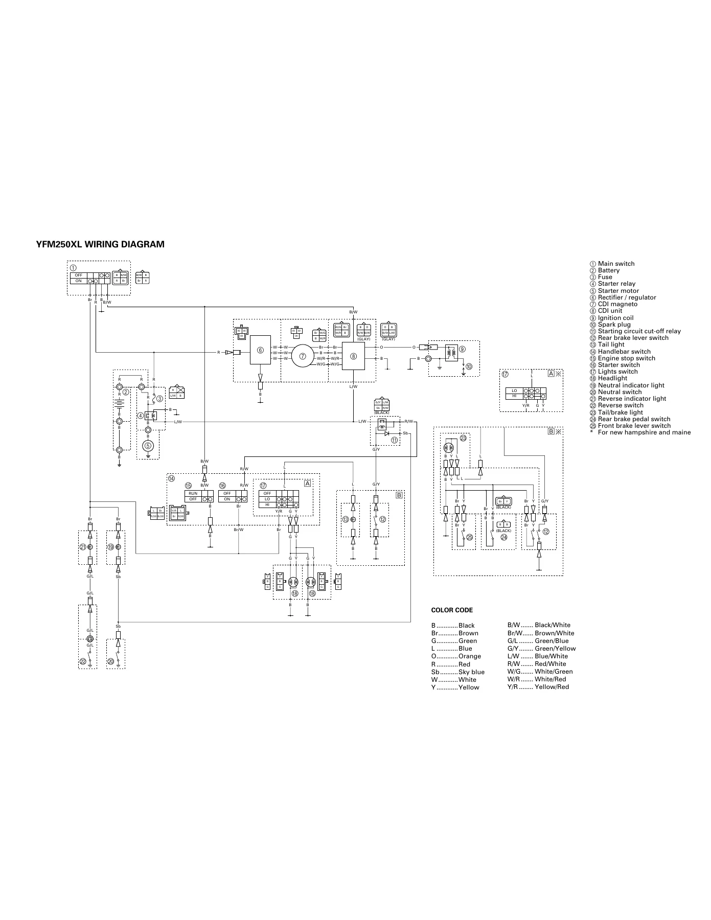
Electrical component layout, switch continuity inspection, bulb checking for the headlights, then a circuit-by-circuit breakdown of the ignition system, electric starting system (with the starting circuit cut-off logic for neutral and brake lever conditions), charging system, lighting system, and signal system. Each system gets its own circuit diagram, troubleshooting flow, and component test values for resistance and voltage. The full fold-out wiring diagram with colour code is included.
Troubleshooting
Organised by symptom: starting failure and hard starting broken into fuel, electrical and compression causes; poor idle speed performance; poor medium and high-speed performance; faulty drive train with the noise-diagnosis chart; faulty gear shifting (hard shifting, pedal will not move, jumps out of gear); clutch slipping and dragging; overheating; faulty brake; shock absorber malfunction; unstable handling; and lighting system faults including headlight dark and bulb burnt out.
Why This Yamaha Bear Tracker 250 Manual Belongs in Your Toolbox
A 250-class utility ATV works hard — plowing, hauling, trail riding — and the YFM250XL Bear Tracker is no exception. When a centrifugal clutch starts slipping, when the middle gear whines under load, when the final drive needs a shim change after a bearing replacement, or when the engine suddenly will not fire and you have to decide whether it is fuel, spark or compression, you want the book Yamaha wrote for the machine, not a forum guess. This Yamaha YFM250XL service manual gives you the exact disassembly order, the torque figures, the wear limits, the shim formulas and the circuit logic that let you diagnose and repair once, correctly.
The coverage runs the whole machine: routine valve clearance and oil changes you can do in the garage, all the way through a complete engine overhaul, middle gear and final drive shim selection, and every electrical circuit on the ATV. Because it bundles the 1998 base manual with the 2000 and 2001 supplementary manuals, owners of the YFM250XLC, YFM250XN and YFM250XP all get the data that applies to their model year — including the later DC-CDI ignition and dual disc front brake changes noted in the supplements.
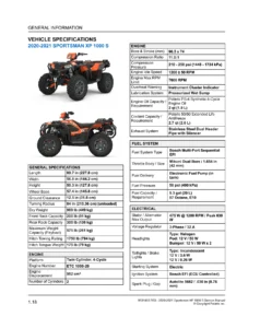
IMAGES PREVIEW
Delivery is instant. The moment your order is confirmed the PDF is available to download — no shipping, no waiting on a paper book. Read it on a laptop in the shop, on a tablet next to the machine, or print just the pages you need for the job and take them to the bench. Every illustration, exploded view, wiring diagram and specification table travels with the file. Whether you are a home mechanic keeping a Bear Tracker alive or a shop technician servicing customer machines, this is the reference that stays open on the bench from the first bolt to the last torque check.
Reviews
There are no reviews yet.