Yamaha YP250 Majesty Service Manual PDF DOWNLOAD
Original price was: $95.00.$28.95Current price is: $28.95.
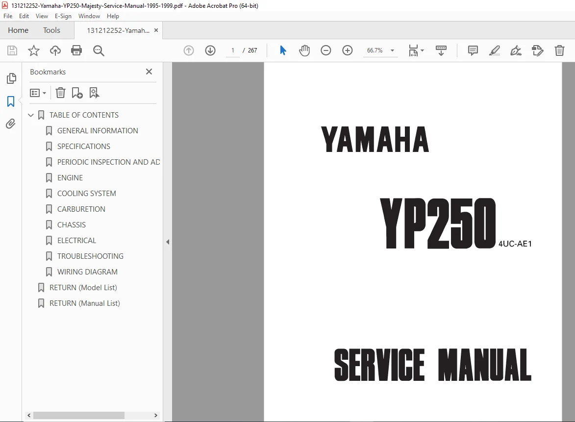
Official Yamaha factory service manual for YP250 Majesty scooter covering 1995-1999 model years. Complete professional repair documentation including engine overhaul, cooling system, carburetion, chassis service, electrical troubleshooting, and periodic maintenance schedules. Essential resource for scooter mechanics and DIY owners performing repairs, maintenance, and adjustments on Yamaha Majesty 250cc scooters. Includes detailed exploded diagrams, torque specifications, and step-by-step procedures.
Description
Yamaha YP250 Majesty Service Manual 1995-1999 Scooter Repair Guide PDF DOWNLOAD
DESCRIPTION
Official Factory Service Manual for Yamaha YP250 Majesty Scooter
This official Yamaha YP250 Majesty service manual provides complete factory repair and maintenance documentation for the popular YP250 Majesty 250cc scooter covering 1995-1999 model years. This comprehensive 250cc scooter repair guide PDF contains detailed exploded diagrams, step-by-step procedures, torque specifications, and professional troubleshooting protocols essential for complete scooter servicing.
FILE DETAILS
- Manual Name: YP250 Service Manual
- Models Covered: Yamaha YP250 Majesty (all regional variants)
- Model Years: 1995, 1996, 1997, 1998, 1999
- Document Code: EB000000
- Manufacturer: Yamaha Motor Company, Ltd.
- Format: Official Factory PDF
- Pages: 267 pages
- Quality: High-resolution factory original with detailed illustrations
- Language: English
- File Size: 5.4 MB
- Publication Date: January 1996 (1st Edition)
- Equipment Type: 250cc Liquid-Cooled CVT Scooter
COMPLETE MANUAL CONTENTS
This Yamaha Majesty maintenance procedures manual is systematically organized into nine comprehensive chapters:
CHAPTER 1: GENERAL INFORMATION
Scooter Identification
- Vehicle Identification Number (VIN) – European specification
- Frame Serial Number – Non-European specifications
- Engine Serial Number – Crankcase stamping location
- Model Label – Location and information under seat
Features
- Oil Indicator Light – Function and operation
- Auto Choke System – Automatic starting enrichment
- Ignition Circuit Cut-Off System – Safety interlock features
Important Information
- Preparation for Removal Procedures – Pre-service requirements
- Replacement Parts – Genuine parts specifications
- Gaskets, Oil Seals, and O-Rings – Always-replace components
- Lock Washers/Plates and Cotter Pins – One-time-use fasteners
- Bearings and Oil Seals – Installation procedures
- Circlips – Proper installation techniques
- Checking of Connections – Verification procedures
- How to Use the Conversion Table – Metric/Imperial conversions
Special Tools
- Complete special tools listing
- Part numbers and applications
- Tool illustrations
- Alternative tool information
CHAPTER 2: SPECIFICATIONS
Complete Technical Specifications
- Engine specifications
- Transmission and final drive
- Chassis dimensions
- Electrical system specifications
- Capacities (fuel, coolant, oil)
- Performance specifications
- Tire specifications
- Suspension specifications
- Brake specifications
- Tightening torques (comprehensive listing)
- Standard/service limits for all components
CHAPTER 3: PERIODIC INSPECTION AND ADJUSTMENT
Preventive Maintenance Procedures
This chapter contains all recommended inspections and adjustments that ensure reliable operation and longer service life.
Periodic Maintenance Schedule
- Daily checks
- Initial service intervals
- Regular maintenance intervals
- Component inspection schedules
Inspection and Adjustment Procedures
- Valve Clearance Adjustment – Inspection and adjustment procedures
- Spark Plug Inspection – Cleaning and replacement
- Engine Oil Replacement – Oil change intervals and procedures
- Air Filter Service – Cleaning and replacement
- Carburetor Synchronization – Idle adjustment
- Throttle Cable Adjustment – Free play setting
- Brake Inspection and Adjustment
- Front brake pad inspection
- Rear brake pad inspection
- Brake fluid level check
- Brake line inspection
- Tire Inspection – Pressure and wear
- Drive Belt Inspection – CVT belt condition check
- Battery Maintenance – Electrolyte level and charging
- Coolant System Inspection – Level check and replacement
- Steering Head Bearing Adjustment – Play elimination
- Front Fork Inspection – Oil level and leaks
- Rear Suspension Adjustment – Preload settings
- Light and Switch Inspection – Electrical system check
- Fastener Inspection – Tightness verification
CHAPTER 4: ENGINE OVERHAUL
Complete Engine Service Documentation
Engine Removal and Installation
- Pre-removal preparation
- Step-by-step removal procedure
- Engine reinstallation
- Post-installation checks
Cylinder Head Service
- Cylinder head removal
- Valve removal and inspection
- Valve guide inspection and replacement
- Valve seat inspection and refacing
- Valve spring inspection
- Camshaft removal and inspection
- Camshaft bearing inspection
- Rocker arm inspection
- Cylinder head installation
Cylinder and Piston
- Cylinder removal
- Piston removal
- Piston ring inspection
- Piston pin inspection
- Cylinder bore inspection and measurement
- Piston-to-cylinder clearance
- Piston installation
- Cylinder installation
Crankcase and Crankshaft
- Crankcase disassembly
- Crankshaft removal
- Crankshaft inspection and measurement
- Connecting rod inspection
- Crankshaft bearing inspection
- Oil pump inspection
- Crankcase assembly
Transmission
- Transmission removal
- Gear inspection
- Shift fork inspection
- Transmission assembly
Clutch System
- Automatic centrifugal clutch operation
- Clutch removal
- Clutch component inspection
- Clutch spring inspection
- Clutch installation
V-Belt Transmission (CVT)
- Driven pulley removal
- Drive pulley removal
- V-belt inspection and replacement
- Pulley face inspection
- Roller weight inspection
- CVT assembly procedures
Starting System
- Electric starter motor removal
- Starter motor inspection
- Starter clutch service
- Kick starter mechanism
CHAPTER 5: COOLING SYSTEM
Liquid Cooling System Service
System Overview
- Cooling system components
- Coolant circulation path
- Thermostat operation
Service Procedures
- Coolant Replacement – Draining and refilling procedures
- Radiator Removal and Installation
- Radiator Inspection – Leak testing
- Radiator Cap Testing – Pressure test procedures
- Water Pump Service
- Water pump removal
- Impeller inspection
- Seal replacement
- Pump installation
- Thermostat Testing – Opening temperature verification
- Cooling Fan Operation – Thermo-switch testing
- Hose and Connection Inspection – Leak prevention
CHAPTER 6: CARBURETION
Fuel and Carburetor System
Carburetor Specifications
- Carburetor type and model
- Jet specifications
- Needle settings
- Float height specifications
Service Procedures
- Carburetor Removal and Installation
- Carburetor Disassembly – Complete breakdown with exploded diagram
- Component Inspection
- Float inspection
- Float valve inspection
- Jet cleaning
- Needle and jet needle inspection
- Throttle valve inspection
- Auto Choke System Service
- Choke mechanism operation
- Electrical testing
- Adjustment procedures
- Carburetor Assembly – Reassembly sequence
- Float Height Adjustment – Precise measurement procedure
- Pilot Screw Adjustment – Idle mixture setting
- Throttle Cable Synchronization
- Fuel Tap Service – Vacuum petcock operation
- Fuel Tank Removal – Access procedures
- Fuel Line Inspection – Leak and flow check
CHAPTER 7: CHASSIS
Frame, Suspension, Brakes, and Wheels
Body Work
- Body panel removal sequences
- Seat removal
- Under-seat storage access
- Cowling removal procedures
- Floor panel removal
Front Wheel
- Front wheel removal
- Front axle inspection
- Wheel bearing inspection and replacement
- Tire mounting and balancing
- Wheel installation and alignment
Rear Wheel
- Rear wheel removal
- Final drive service
- Wheel bearing replacement
- Brake drum inspection (if equipped)
- Wheel installation
Front Brake System
- Brake pad inspection and replacement
- Brake caliper service
- Master cylinder overhaul
- Brake disc inspection
- Brake fluid replacement
- Brake line inspection
- Air bleeding procedure
Rear Brake System
- Brake pad/shoe inspection
- Brake caliper service (disc brake)
- Brake drum service (drum brake)
- Master cylinder service
- Brake adjustment
- Brake fluid system service
Front Fork
- Fork removal
- Fork disassembly
- Fork oil replacement
- Spring inspection
- Damper rod inspection
- Fork seal replacement
- Fork assembly and installation
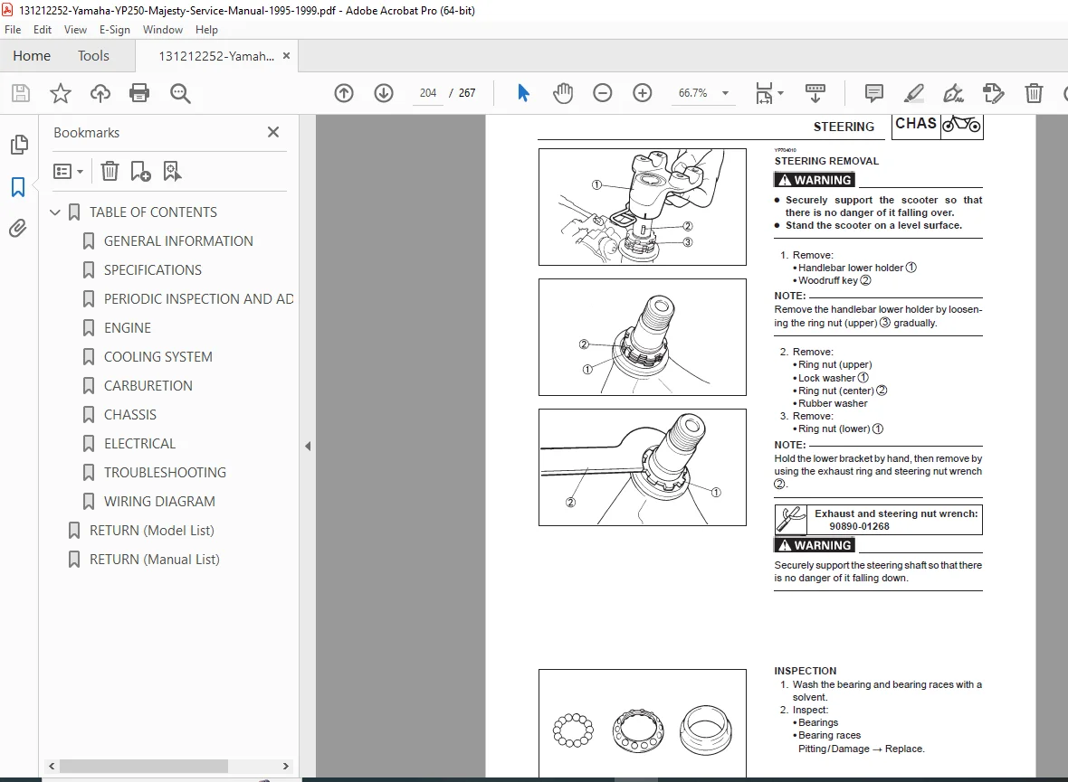
Steering System
- Handlebar removal
- Steering head bearing inspection
- Steering head adjustment
- Steering lock mechanism
- Cable routing and lubrication
Rear Suspension and Swingarm
- Rear shock absorber removal
- Shock inspection and testing
- Preload adjustment
- Swingarm removal
- Swingarm bearing inspection
- Swingarm pivot inspection
Final Drive
- Final drive oil change
- Gear inspection
- Output shaft seal replacement
CHAPTER 8: ELECTRICAL SYSTEM
Complete Electrical Service Documentation
Charging System
- Alternator/stator inspection
- Rotor inspection
- Output testing
- Voltage regulator/rectifier testing
- Charging system troubleshooting
Ignition System
- CDI (Capacitor Discharge Ignition) operation
- Ignition coil testing
- Spark plug cap inspection
- Pickup coil testing
- Ignition timing verification
- Kill switch operation
Electric Starting System
- Starter motor testing
- Starter relay operation
- Starting circuit troubleshooting
- Starter switch inspection
Lighting System
- Headlight aiming adjustment
- Bulb replacement procedures
- Tail light service
- Brake light switch adjustment
- Turn signal operation
- License plate light
Instruments and Gauges
- Speedometer cable service
- Speedometer drive inspection
- Fuel gauge operation
- Temperature gauge testing
- Indicator light circuits
Switches and Controls
- Handlebar switch inspection
- Ignition switch service
- Side stand switch testing
- Brake light switches
Battery
- Battery removal and installation
- Charging procedures
- Electrolyte level maintenance
- Battery testing
- Terminal cleaning
Wiring Diagrams
- Complete color-coded wiring schematics
- Circuit descriptions
- Connector locations
- Fuse and relay locations
- Troubleshooting flowcharts
CHAPTER 9: TROUBLESHOOTING
Systematic Fault Diagnosis
Engine Troubleshooting
- Engine won’t start
- Engine starts but won’t run
- Poor engine performance
- Engine overheating
- Engine noise diagnosis
- Unusual vibration
- Smoke from exhaust
- Poor fuel economy
Transmission/CVT Troubleshooting
- Poor acceleration
- Belt slippage
- Clutch problems
- Drive belt noise
- Transmission issues
Electrical System Troubleshooting
- No spark
- Weak spark
- Battery won’t charge
- Battery drains quickly
- Lights don’t work
- Starter won’t turn
- Fuses blow repeatedly
Chassis Troubleshooting
- Brake problems (front and rear)
- Steering wobble or shimmy
- Front fork problems
- Rear suspension issues
- Handling problems
- Tire wear patterns
Troubleshooting Charts
- Symptom-based diagnosis trees
- Systematic elimination procedures
- Test procedures with specifications
- Common problems and solutions
WHO NEEDS THIS SCOOTER ENGINE OVERHAUL MANUAL?
This YP250 electrical troubleshooting guide is essential for:
- Scooter Mechanics – Professional repair shop technicians
- Yamaha Dealership Technicians – Authorized service centers
- DIY Scooter Owners – Enthusiasts performing own maintenance
- Scooter Restoration Specialists – Rebuilding classic Majesty models
- Motorcycle Training Schools – Teaching scooter repair
- Mobile Mechanics – On-site scooter service providers
- Fleet Maintenance Operators – Delivery/rental fleet servicing
KEY FEATURES OF THIS MAJESTY TECHNICAL SPECIFICATIONS MANUAL
COMPREHENSIVE CVT COVERAGE
Detailed documentation of the automatic V-belt transmission system including pulley service, belt replacement, and roller weight inspection.
LIQUID COOLING SYSTEM
Complete cooling system service procedures for the water-cooled 250cc engine including radiator service, water pump overhaul, and thermostat testing.
FACTORY-AUTHORIZED PROCEDURES
Official Yamaha engineering documentation ensures proper repair techniques and maintains scooter reliability and safety.
DETAILED EXPLODED DIAGRAMS
Clear illustrations at the start of every service section showing component relationships and assembly sequences.
AUTO CHOKE SYSTEM
Comprehensive coverage of the automatic choke system unique to this model, including testing and adjustment procedures.
COMPLETE TORQUE SPECIFICATIONS
All critical fastener torques listed for proper assembly and prevention of damage.
STEP-BY-STEP FORMAT
Procedures presented in logical sequence with accompanying illustrations for clarity.
TECHNICAL SPECIFICATIONS COVERED
| Specification | Details |
|---|---|
| Engine Type | Single cylinder, 4-stroke, SOHC |
| Displacement | 249cc |
| Cooling System | Liquid-cooled |
| Transmission | CVT (Continuously Variable Transmission) |
| Starting System | Electric start with kick start backup |
| Ignition System | CDI (Capacitor Discharge Ignition) |
| Fuel System | Carburetor with auto choke |
| Drive System | V-belt automatic with final gear reduction |
MAINTENANCE COVERAGE
Routine Service:
- Oil changes and filter service
- Air filter maintenance
- Valve clearance inspection
- Spark plug service
- Drive belt inspection
- Coolant replacement
- Brake system maintenance
- Battery service
- Tire pressure and condition
Major Service:
- Valve adjustment
- Carburetor cleaning and synchronization
- Brake fluid replacement
- Fork oil replacement
- Final drive oil change
- Coolant system flush
- Complete electrical inspection
SPECIAL FEATURES DOCUMENTED
Oil Indicator Light System:
- Low oil level warning
- Sensor operation and testing
- Troubleshooting procedures
Ignition Circuit Cut-Off System:
- Safety interlock operation
- Side stand switch integration
- Troubleshooting and bypass (for testing only)
Auto Choke System:
- Temperature-activated enrichment
- Electrical operation
- Testing procedures
- Adjustment methods
CVT SYSTEM EXPERTISE
V-Belt Transmission Components:
- Drive pulley (engine side)
- Driven pulley (rear wheel side)
- V-belt inspection and replacement
- Roller weights and sliding sleeve
- Torque spring specifications
- Clutch operation and service
CVT Service Procedures:
- Belt wear limit inspection
- Pulley face condition check
- Roller weight replacement
- Spring testing
- Proper reassembly sequences
- CVT cover gasket replacement
ENGINE OVERHAUL CAPABILITIES
✓ Complete Teardown – Full engine disassembly with component identification
✓ Inspection Procedures – Wear limit specifications for all major components
✓ Valve Service – Grinding, lapping, guide replacement
✓ Piston/Cylinder Service – Bore measurement, piston selection, ring installation
✓ Crankshaft Inspection – Runout measurement, bearing replacement
✓ Transmission Overhaul – Gear inspection, shift mechanism service
✓ Oil Pump Service – Clearance inspection, seal replacement
COOLING SYSTEM SERVICE
Water Pump Overhaul:
- Impeller removal
- Mechanical seal replacement
- Housing inspection
- Performance testing
Radiator Service:
- Pressure testing procedures
- Cap testing specifications
- Core cleaning methods
- Leak repair guidance
Thermostat Testing:
- Opening temperature verification
- Replacement procedures
- System bleeding after service
ELECTRICAL SYSTEM DIAGNOSTICS
Wiring Diagrams Include:
- Complete color-coded schematics
- Charging system circuits
- Ignition system circuits
- Lighting circuits
- Starting system
- Switch and relay locations
- Connector identification
- Ground points
Testing Procedures:
- Voltage measurements
- Resistance testing
- Continuity checks
- Component isolation testing
- Circuit tracing methods
ILLUSTRATED SYMBOLS SYSTEM
Manual uses comprehensive symbol system:
- Maintenance with engine mounted
- Fluid filling points
- Lubrication requirements
- Special tool applications
- Tightening torques
- Wear limits and clearances
- Engine speed specifications
- Electrical values (Ω, V, A)
Lubrication Symbols:
- Engine oil application points
- Gear oil requirements
- Molybdenum disulfide oil
- Wheel bearing grease
- Lithium-soap base grease
- Molybdenum disulfide grease
- Locking agent application
- New parts installation indicators
WHAT YOU’LL RECEIVE
Upon purchase, you receive instant download access to the complete 267-page Yamaha YP250 Majesty service manual in PDF format. This is the identical factory manual used by Yamaha dealership technicians worldwide, containing every specification, procedure, diagram, and troubleshooting chart needed for professional-level scooter maintenance and repair from routine service to complete engine overhaul.
Don’t risk improper repairs or incomplete service information—get the official factory manual with complete CVT system coverage, liquid cooling procedures, and electrical diagrams trusted by professional Yamaha technicians worldwide. Download instantly and service your Majesty 250 scooter with complete factory-level confidence today!