Yanmar 3TNV-4TNV Series Diesel Engine Service Manual – PDF DOWNLOAD
Original price was: $120.00.$33.95Current price is: $33.95.
Yanmar 3TNV-4TNV Series Diesel Engine Service Manual – PDF DOWNLOAD
YANMAR
M996 l – 02E050
Description
Yanmar 3TNV-4TNV Series Diesel Engine Service Manual – PDF DOWNLOAD
DESCRIPTION:
Yanmar 3TNV-4TNV Series Diesel Engine Service Manual – PDF DOWNLOAD
PREFACE
- This manual describes the service procedures for the TNV series engines of indirect injection system that have been certified by the US EPA, California ARB and/or the 97/68/EC Directive for industrial use.
- Please use this manual for accurate, quick and safe servicing of the said engine. Since the explanation in this manual assumes the standard type engine, the specifications and components may partially be different from the engine installed on individual work equipment (power generator, pump, compressor, etc.).
- Please also refer to the service manual for each work equipment for details. The specifications and components may be subject to change for improvement of the engine quality without notice. If any modification of the contents described herein becomes necessary, it will be notified in the form of correction information each time.
SAFETY LABELS •
- Most accidents are caused by negligence of basic safety rules and precautions. For accident prevention, it is important to avoid such causes before development to accidents. Please read this manual carefully before starting repair or maintenance to fully understand safety precautions and appropriate inspection and maintenance procedures.
- Attempting at a repair or maintenance job without sufficient knowledge may cause an unexpected accident. • It is impossible to cover every possible danger in repair or maintenance in the manual. Sufficient consideration for safety is required in addition to the matters marked [ A CAUTION : Especially for safety precautions in a repair or maintenance job not described in this manual, receive instructions from a knowledgeable leader.
- Safety marks used in this manual and their meanings are as follows:
TABLE OF CONTENTS:
Yanmar 3TNV-4TNV Series Diesel Engine Service Manual – PDF DOWNLOAD
1 General 1
11 Engine Nomenclature 1
12 Specifications 1
13 Fuel Oil, Lubricating Oil and Cooling Water 14
131 Fuel oil 14
1 32 Lubricating oil 15
133 Cooling water 15
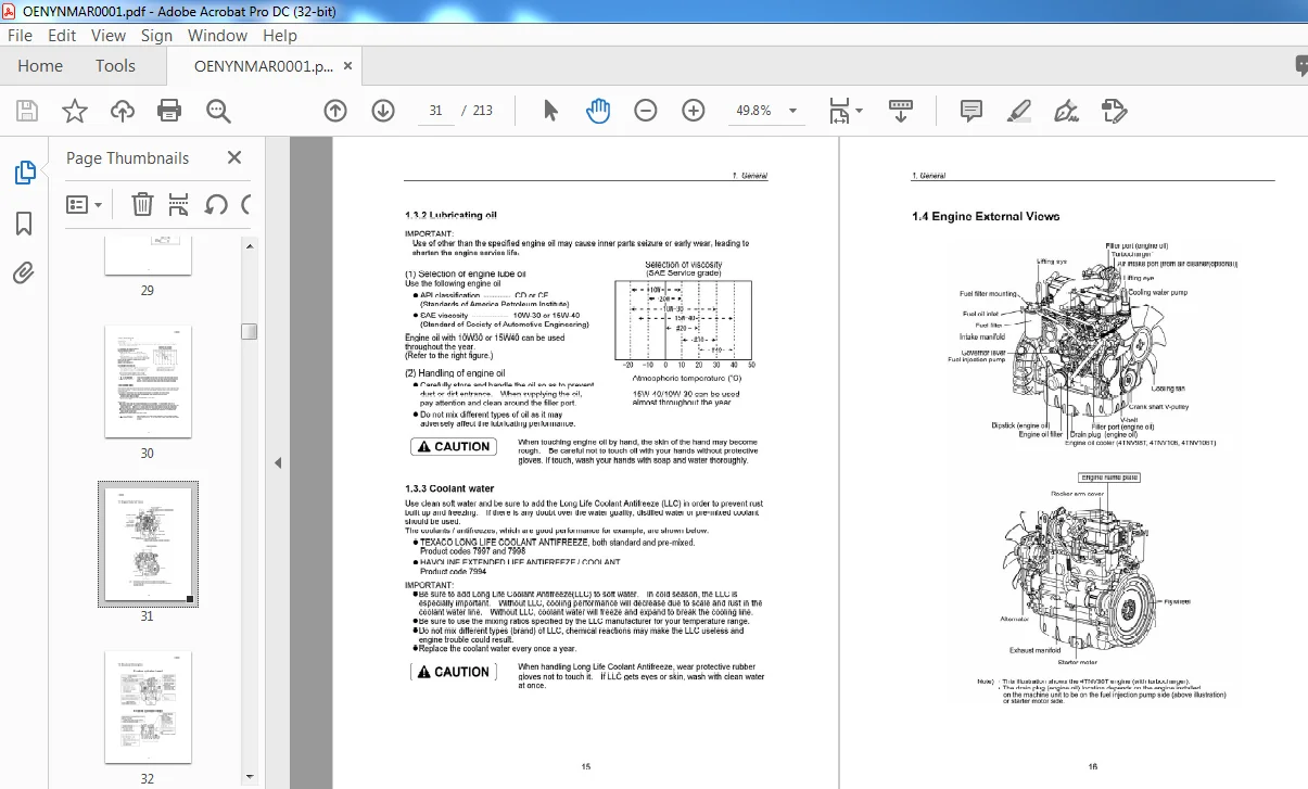
14 Engine External Views 16
15 Structural Description 17
16 Exhaust gas emission regulation 18
1 61 The Emission Standard in USA 18
162 Engine identification 19
163 Guarantee Conditions for the EPA Emission Standard 20
2 Inspection and Adjustment 22
21 Periodic Maintenance Schedule 22
22 Periodic Inspection and Maintenance Procedure 23
221 Check before Daily Operation 23
222 inspection after initial 50 hours operation 25
223 Inspection every 50 hours 28
224 Inspection every 250 hours or 3 months 32
225 Inspection every 500 hours or 6 months 35
226 Inspection every 1,000 hours or one year 37
227 Inspection every 2000 hours or 2 years 46
23 Adjusting the no-load maximum or minimum speed 49
24 sensor Inspection 50
241 Oil pressure switch 50
242 Thermo switch 50
25 Water leak check in cooling water system 50
26 Radiator cap inspection 51
27 Thermostat Inspection 51
28 Adjusting Operation 52
29 Long storage 52
3 TROUBLESHOOTING 53
31 Preparation before troubleshooting 53
32 Quick Reference Table for Troubleshooting 54
33 Troubleshooting by measuring Compression Pressure 57
4 Disassembly, Inspection and Reassembly of Engines 59
41 Complete disassembly and reassembly 59
41 1 Introduction 59
41 2 Special service tools 60
413 Complete disassembly 65
414 Precautions before and during reassembly 69
415 Adjusting operation 69
42 Cylinder Head: Disassembly, Inspection and Reassembly 70
421 Components (2-valve cylinder head) 70
422 Disassembly procedure: 70
423 Reassembly procedure: 71
4 24 Servicing points 72
425 Parts Inspection and measurement 76
426 Valve seat correction 80
427 Valve guide replacement 81
428 Valve stem seal replacement 82
43 Gear Train and Camshaft 83
431 Components 83
432 Disassembly procedure: 83
433 Reassembly procedure: 83
434 Servicing points 84
435 Parts inspection and measurement 87
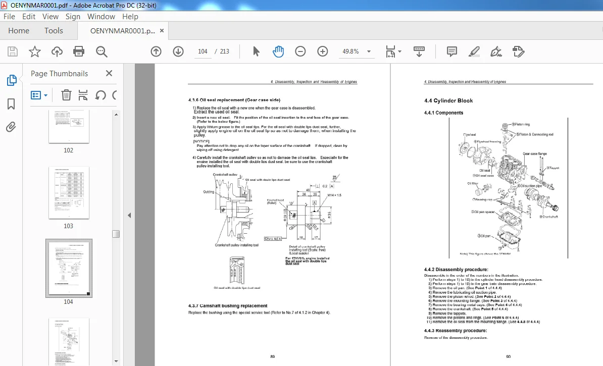
436 Oil seal replacement (Gear case side) 89
437 Camshaft bushing replacement 89
44 Cylinder Block 90
441 Components 90
442 Disassembly procedure: 90
443 Reassembly procedure: 90
444 Servicing points 91
445 Parts inspection and measurement 95
446 Cylinder bore correction 106
447 Piston pin bushing replacement 107
4 4 8 Oil seal replacement (Flywheel housing side) 107
5 LUBRICATION SYSTEM 108
51 Lubrication System Diagram 108
52 Trochoid Pump Components 109
53 Disassembly(Reverse the procedure below for assembly) 109
54 Servicing Points 109
55 Parts Inspection and Measurement 110
551 Trochoid pump inspection and measurement 110
6 COOLING SYSTEM 112
61 Cooling Water System 112
62 Cooling Water Pump Components 112
63 Disassembly (Reverse the procedure below for assembly) 113
64 Servicing Points 113
7 FUEL INJECTION PUMP/GOVERNOR 114
71 Introduction 114
72 Fuel Injection Pump 114
7 21 Fuel system diagram 114
7 22 External view and components 115
7 23 Disassembly procedure: 115
724 Assembly procedure 116
725 Servicing points 116
8 TURBOCHAGER: Disassembly, inspection and reassembly 118
81 Structure and Functions 118
811 Main specifications 118
8 1 2 Construction 118
81 3 Structural and functional outline 119
814 Components 120
82 Service Standards and Tightening Torque 121
821 Service standards 121
822 Tightening torque 122
83 Periodic Inspection Procedure 123
831 Periodic inspection intervals 123
832 Inspection procedure 124
833 Waste gate valve adjustment procedure 125
84 Disassembly Procedure 127
841 Preparation for disassembly 127
842 Inspection before disassembly 128
843 Disassembly 128
85 Washing and Inspection procedure 130
851 washing 130
852 Inspection procedure 131
86 Reassembly Procedure 134
861 Preparation for reassembly 134
862 Reassembly 134
87 Handling after Disassembly and Reassembly 137
871 Instructions for turbocharger installation 137
88 Troubleshooting 138
881 Excessively exhaust smoke 138
882 White smoke generation 138
883 Sudden oil decrease 139
884 Decrease in output 139
885 Poor (slow) response (starting) of turbocharger 139
886 Abnormal sound or vibration 139
9 STARTING MOTOR 140
91 For 4 TNV94U 98 140
911 Specifications 140
912 Components 141
9 13 Troubleshooting 142
914 Names of parts and disassembly procedure 143
915 Inspection and Maintenance 147
916 Service standards 152
91 7 Assembly 153
918 Characteristic test 155
92 For 4 TNV106(T) 156
921 Specifications 156
9 22 Congiguration drawing 156
92 3 Troubleshooting 157
924 Component names and disassembly procedure 158
925 Disassembly procedure 159
926 Inspection and maintenance 167
927 Assembly 173
9 28 Adjustment 174
929 Service standards 175
10 ALTERNATOR 176
101 The 40AAlternator for 3TNV84 and other models 176
1011 Components 176
1012 Specifications 177
1013 Wiring diagram 177
1014 Standard output characteristics 178
1015 Inspection 178
102 Troubleshooting 179
11 ELECTRIC WIRING 180
111 Electric Wiring Diagram 180
112 PRECAUTION ON ELECTRIC WIRING 181
11 21 Alternator 181
11 22 Starter 182
11 23 Current limiter 183
1124 Section area and resistance of electric wire 184
12 SERVICE STANDARDS 185
121 Engine Tuning 185
122 Engine Body 186
1221 Cylinder head 186
1222 Gear train and camshaft 189
1223 Cylinder block 190
123 Lubricating Oil System (frochoid Pump) 195
1231 Outside clearance of outer rotor 195
1232 Side clearance of outer rotor 195
1233 Inside clearance of inner rotor 195
1234 Rotor shaft clearance 195
13 TIGHTENING TORQUE for BOLTS and NUTS 196
131 Tightening Torques for Main Bolts and Nuts 196
132 Tightening Torques for standard Bolts and Nuts 197
YANMAR 3TNV-4TNV SERIES DIESEL ENGINE SERVICE MANUAL – PDF DOWNLOAD:
IMAGES PREVIEW OF THE MANUAL:
PLEASE NOTE:
- This is the SAME MANUAL used by the dealerships to diagnose your vehicle
- No waiting for couriers / posts as this is a PDF manual and you can download it within 2 minutes time once you make the payment.
- Your payment is all safe and the delivery of the manual is INSTANT – You will be taken to the DOWNLOAD PAGE.
- So have no hesitations whatsoever and write to us about any queries you may have : heydownloadss @gmail.com
S.M