Yanmar 4TNE92-NMH • 4TNE92-NMHA 4TNE98-NMH TNE SERIES INDUSTRIAL ENGINES SERVICE MANUAL 0B2991-U0001 – PDF DOWNLOAD
Original price was: $85.95.$28.95Current price is: $28.95.
Yanmar 4TNE92-NMH • 4TNE92-NMHA 4TNE98-NMH TNE SERIES INDUSTRIAL ENGINES SERVICE MANUAL 0B2991-U0001 – PDF DOWNLOAD
Description
Yanmar 4TNE92-NMH • 4TNE92-NMHA 4TNE98-NMH TNE SERIES INDUSTRIAL ENGINES SERVICE MANUAL 0B2991-U0001 – PDF DOWNLOAD
IMAGES PREVIEW OF THE MANUAL:
DESCRIPTION:
Yanmar 4TNE92-NMH • 4TNE92-NMHA 4TNE98-NMH TNE SERIES INDUSTRIAL ENGINES SERVICE MANUAL 0B2991-U0001 – PDF DOWNLOAD
INTRODUCTION:
- This manual describes the service procedures for the TNE series indirect injection engines. These engines are certified by the U.S. EPA, California ARB and/or the 97/68/EC Directive for industrial use.
- Please use this manual for accurate, quick and safe servicing of the engine. Since the directions in this manual are for a typical engine, some specifications and components may be different from your engine. Refer to the documentation supplied by the optional equipment manufacturer for specific service instructions.
- Yanmar products are continuously under going improvement. This Service Manual might not address possible field modifications to the equipment. Contact an authorized Yanmar industrial engine dealer or distributor for answers to any questions relating to field modifications.
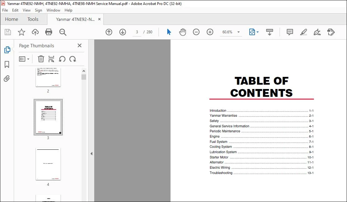
TABLE OF CONTENTS:
Yanmar 4TNE92-NMH • 4TNE92-NMHA 4TNE98-NMH TNE SERIES INDUSTRIAL ENGINES SERVICE MANUAL 0B2991-U0001 – PDF DOWNLOAD
Introduction 5
Yanmar Warranties 7
Yanmar Limited Warranty 9
What is Covered by this Warranty? 9
How Long is the Warranty Period? 9
What the Engine Owner Must Do: 9
To Locate an Authorized Yanmar Industrial Engine 9
Dealer or Distributor: 9
What Yanmar Will Do: 9
What is Not Covered by this Warranty? 10
Warranty Limitations: 10
Warranty Modifications: 10
Questions: 10
Customer Registration 10
Yanmar Co , Ltd Limited Emission Control 11
System Warranty – USA Only 11
Your Warranty Rights and Obligations: 11
California 11
Manufacturer’s Warranty Period: 11
Warranty Coverage: 12
Warranted Parts: 12
Exclusions: 13
Owner’s Warranty Responsibilities: 13
Safety 15
Safety Statements 15
Safety Precautions 16
Before You Operate 16
During Operation and Maintenance 16
General Service Information 29
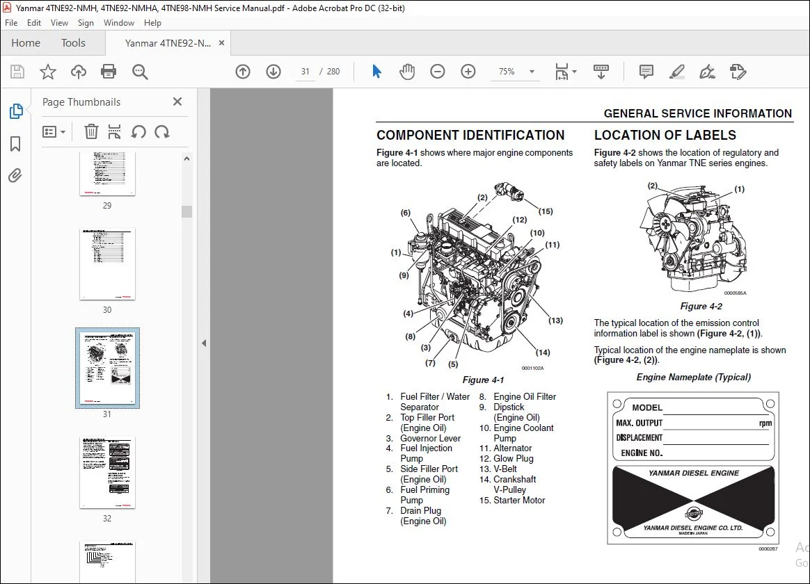
Component Identification 31
Location of Labels 31
EPA / ARB Emission Control Regulations – USA Only 32
Emission Control Labels 32
EPA / ARB Labels 32
The 97/68/EC Directive Certified Engines 32
Engine Family 33
Function of Major Engine Components 34
Function of Cooling System Components 36
Diesel Fuel 37
Diesel Fuel Specifications 37
Additional Technical Fuel Requirements 37
Bio-Diesel Fuels 37
Filling The Fuel Tank 38
Priming the Fuel System 40
Engine Oil 42
Engine Oil Specifications 42
Service Categories 42
Definitions 42
Additional Technical Engine oil Requirements: 42
Engine Oil Viscosity 42
Checking Engine Oil 43
Adding Engine Oil 43
Engine Oil Capacity (Typical) 43
Engine Coolant 44
Engine Coolant Specifications 44
Alternative Engine Coolant 44
Additional Technical Coolant Specifications: 45
Filling Radiator With Engine Coolant 45
Engine Coolant Capacity (Typical) 46
Specifications 47
Description of Model Number 47
Engine Speed Specifications 47
Engine General Specifications 47
Principal Engine Specifications 48
4TNE92-NMH 48
4TNE92-NMHA 49
4TNE98-NMH 50
Engine Service Information 51
Engine Tuning 51
Tightening Torques for Standard Bolts and Nuts 52
Standard Torque Chart 53
Abbreviations and Symbols 54
Abbreviations 54
Symbols 54
Unit Conversions 55
Unit Prefixes 55
Prefix 55
Symbol 55
Power 55
Units of Length 55
Units of Volume 55
Units of Mass 55
Units of Force 55
Units of Torque 55
Units of Pressure 55
Units of Power 55
Units of Temperature 55
Periodic Maintenance 57
Precautions 72
The Importance of Periodic Maintenance 72
Performing Periodic Maintenance 72
Yanmar Replacement Parts 72
Required EPA / ARB Maintenance – USA Only 72
EPA / ARB Installation Requirements – USA Only 72
Tightening Fasteners 72
Standard Torque Chart 73
Periodic Maintenance Schedule 73
Periodic Maintenance Procedures 75
Daily 75
Drain Fuel Filter / Water Separator 75
Check Fuel Hoses and Engine Coolant Hoses 76
Every 250 Hours of Operation 77
Check and Clean Radiator Fins 77
Check and Adjust Cooling Fan V-belt 78
Check Battery 79
Clean Air Cleaner Element 80
Every 500 Hours of Operation 82
Replace Engine Oil and Engine Oil Filter 82
Check and Adjust the Governor Lever and Engine Speed Control 84
Every 1000 Hours of Operation 85
Adjust Intake / Exhaust Valve Clearance 85
Clean Fuel Filter / Water Separator 85
Replace Fuel Filter 87
Every 2000 Hours of Operation 90
Replace Air Cleaner Element 90
Inspect Clean and Test Fuel Injectors 90
Every 4000 Hours of Operation 91
Drain, Flush, and Re-fill the Coolant System with New Coolant 91
Replace Fuel Hoses and Engine Coolant Hoses 92
Engine 93
Engine Service Information 97
Engine Body 97
Cylinder Head 97
Intake / Exhaust Valve and Guide 97
Valve Spring 98
Rocker Arm and Shaft 98
Push Rod 98
Gear Train and Camshaft 99
Camshaft 99
Idler Gear Shaft and Bushing 99
Backlash of Each Gear 100
Cylinder Block 100
Crankshaft 100
Thrust Bearing 101
Piston 101
Piston Ring 102
Connecting Rod 102
Tappet 103
Engine Special Torque Chart 104
Special Service Tools 105
Measuring Instruments 107
Before You Begin Servicing 110
Removal of Engine 111
Cylinder Head Components 112
Disassembly of Cylinder Head 113
Removal of Glow Plugs 114
Removal of Valve Cover 114
Removal of Rocker Arm Assembly 114
Disassembly of Rocker Arm Assembly 115
Removal of Cylinder Head 115
Removal of Intake / Exhaust Valves 116
Removal of Valve Guides 116
Cleaning of Cylinder Head Components 117
Inspection of Cylinder Head Components 117
Inspection of Push Rods 117
Inspection of Rocker Arm Assembly 118
Inspection of Valve Guides 118
Inspection of Cylinder Head 118
Inspection of Intake and Exhaust Valves 118
Inspection of Valve Springs 120
Assembly of Cylinder Head 120
Assembly of Valve Guides 120
Assembly of Intake and Exhaust Valves 121
Assembly of Cylinder Head 122
Assembly of Rocker Arm Assembly 122
Assembly of the Valve Cover 123
Assembly of Glow Plugs 123
Measuring and Adjusting Valve Clearance 124
Valve Clearance Measurement 124
Valve Clearance Adjustment 125
Drive Train and Camshaft Components 126
Disassembly of Drive Train and Camshaft Components 127
Removal of Oil Pan 128
Removal of Oil Sump Pump 128
Removal of Timing Gears 128
Removal of Pistons 129
Removal of Crankshaft 130
Removal of Camshaft 131
Removal of Gear Case 132
Inspection of Drive Train and Camshaft Components 132
Inspection of Cylinder Block 132
Inspection of Pistons 136
Inspection of Piston Pin 136
Inspection of Connecting Rod 137
Inspection of Tappets 137
Inspection of Crankshaft 137
Inspection of Camshaft 138
Inspection of Camshaft Bushings 139
Inspection of Idler Gear and Shaft 139
Honing and Boring 140
Assembly of Drive Train and Camshaft Components 141
Assembly of Pistons 141
Installation of Gear Case 142
Installation of Crankshaft 142
Installation of Pistons 143
Installation of Camshaft 144
Installation of Timing Gears 144
Installation of Gear Case Cover 145
Installation of Oil Sump Pump 145
Installation of Oil Pan 145
Fuel System 147
Fuel System Special Torque Chart 149
Measuring Instruments 149
Fuel System Components 152
Fuel System Diagram 153
Structure and Operation of Fuel Injection Pump 155
Overview 156
Pump 156
Governor 156
Timer 157
Feed Pump (Vane Type) 157
Regulating Valve 158
Plunger Operation 159
Process 160
Suction Process 160
Injection Process 160
End of Injection 161
Uniform Pressure Process 161
Reverse Rotation Prevention Mechanism 162
Fuel Injection Volume Adjustment Mechanism 162
Delivery Valve Assembly 163
Delivery Valve Holder with Damping Valve 163
All -Speed Governor 164
At Start of Engine 166
During Idling 167
At Full-Load Maximum Speed Control 168
At No-Load Maximum Speed Control 169
Full-Load Position Adjustment Mechanism 170
Structure and Operation of Timer 171
Standard Type Automatic Timer 171
Magnetic Valve (Stop Solenoid) 172
Before You Begin Servicing 173
Removal of Fuel Injection Pump 174
Installation of the Fuel Injection Pump 177
Checking / Adjustment of Fuel Injection Timing 179
Servicing the Fuel Injectors 181
Removal of the Fuel Injectors 181
Inspection and Testing of the Fuel Injectors 182
Test Procedure Using a Nozzle Tester 182
Judgement Criteria on Atomization Condition 184
Cleaning of Nozzle 185
Installation of Fuel Injectors 185
Cooling System 187
Measuring Instruments 190
Cooling System Diagram 192
Model 4TNE92-NMHA 192
Models 4TNE92-NMH and 4TNE98-NMH 193
Engine Coolant Pump Components 194
Model 4TNE92-NMHA 194
Models 4TNE92-NMH and 4TNE98-NMH 195
Before You Begin Servicing 196
Engine Coolant System Check 197
Disassembly of Engine Coolant Pump 198
Disassembly of the 4TNE92-NMHA Coolant Pump 199
Disassembly of the 4TNE92-NMH and 4TNE98-NMH 199
Coolant Pumps 199
Cleaning and Inspection 200
Thermostat 200
Radiator Cap 200
Assembly of Engine Coolant Pump 201
Assembly of the 4TNE92-NMHA Coolant Pump 201
Assembly of the 4TNE92-NMH and 4TNE98-NMH 201
Coolant Pumps 201
Assembly of All Coolant Pump Models 202
Lubrication System 205
Oil Pump Service Information 209
Engine Oil Pressure – All Models 209
Outer Rotor Outside Clearance – All Models 209
Outer Rotor Side Clearance – All Models 209
Outer Rotor to Inner Rotor Tip Clearance – All Models 209
Rotor Shaft Clearance – All Models 209
Lubrication System Diagram 210
Checking Engine Oil Pressure 211
Oil Pump Components 211
Before You Begin Servicing 211
Disassembly of Oil Pump 213
Cleaning and Inspection 213
Check Outer Rotor Outside Clearance 214
Outer Rotor to Inner Rotor Tip Clearance 214
Check Outer Rotor Side Clearance 214
Check Rotor Shaft Clearance 214
Assembly of Oil Pump 215
Starter Motor 217
Starter Motor Service Information 221
Starter Motor Troubleshooting 222
Starter Motor Precautions 223
Starter Motor Servicing 224
Starter Motor Components 224
Before You Begin 225
Starter Motor Removal 226
Starter Motor Disassembly 226
Inspection 228
Armature 228
Field Coil 230
Brush Holder 231
Magnetic Switch 232
Pinion Clutch Assembly 233
Starter Motor Assembly 234
Check Pinion Projection Length 235
No Load Test 236
Starter Motor Installation 236
Alternator 237
Alternator Service Information 242
Alternator Troubleshooting 243
Alternator Precautions 244
Alternator Components 245
Alternator Servicing 246
Before You Begin Servicing 246
Removal of Alternator 247
Disassembly of Alternator 248
Inspection 251
Stator Coil 251
Rotor 251
Rectifier 252
IC Regulator 253
Diode 255
Brush 255
Assembly of Brush Holder 256
Assembly of Alternator 258
Installation of Alternator 259
Bench Test 260
Test Wiring 261
Regulated Voltage Check 262
No Load Test 262
Output Test 262
Electric Wiring 263
Electric Wiring Precautions 265
Electrical Wire Resistance 266
Battery Cable Resistance 267
Electrical Wire Sizes – Voltage Drop 268
Conversion of AWG to European Standards 269
Electric Wiring Diagram 270
Troubleshooting 271
Special Service Tools 273
Troubleshooting By Measuring Compression Pressure 274
Compression Pressure Measurement Method 274
Standard Compression Pressure 275
Engine Speed and Compression Pressure (Use for Reference) 275
Measured Value and Troubleshooting 276
Quick Reference Table For Troubleshooting 276
Customer Support: [email protected]
https://vimeo.com/740224348
PLEASE NOTE:
- This is the SAME MANUAL used by the dealerships to diagnose your vehicle
- No waiting for couriers / posts as this is a PDF manual and you can download it within 2 minutes time once you make the payment.
- Your payment is all safe and the delivery of the manual is INSTANT – You will be taken to the DOWNLOAD PAGE.
- So have no hesitations whatsoever and write to us about any queries you may have : heydownloadss @gmail.com
I.G