
Yanmar B08-3 Mini Excavator Parts Catalog – US & Australia – PDF Parts Manual
Original price was: $41.95.$27.95Current price is: $27.95.
Complete Yanmar B08-3 crawler backhoe parts catalog for US and Australia models, covering labels, engine, hydraulics, undercarriage, control valve, boom, arm, bucket, blade and every major assembly with genuine part numbers.
Description
File Details
- Manual Type: Parts Catalog (Parts Manual)
- Brand: Yanmar
- Model: B08-3 (US), B08-3 (AS)
- Engine: 2TNE68-EBVA
- Language: English
- File Format: PDF
- Page Count: 135 pages
- Document Number: 000Y00S4171
- Edition: 1st Revised
- Date: June 2004
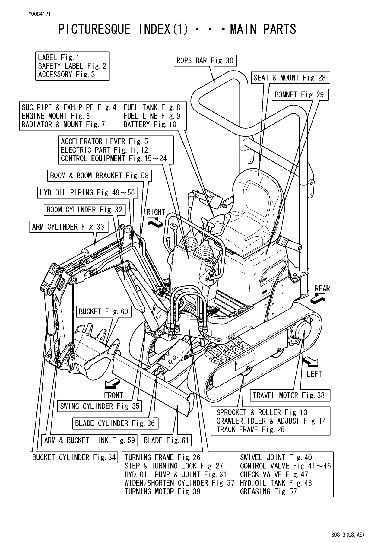
Sections Covered in the Yanmar B08-3 Parts Catalog
- Fig. 1 LABEL
- Fig. 2 SAFETY LABEL
- Fig. 3 ACCESSORY
- Fig. 4 SUC. PIPE & EXH. PIPE
- Fig. 5 ACCELERATOR LEVER
- Fig. 6 ENGINE MOUNT
- Fig. 7 RADIATOR & MOUNT
- Fig. 8 FUEL TANK
- Fig. 9 FUEL LINE
- Fig. 10 BATTERY
- Fig. 11 ELECTRIC PART (WIRING)
- Fig. 12 ELECTRIC PART (EQUIPMENT)
- Fig. 13 SPROCKET & ROLLER
- Fig. 14 CRAWLER, IDLER & ADJUST
- Fig. 15–24 CONTROL EQUIPMENT
- Fig. 25 TRACK FRAME
- Fig. 26 TURNING FRAME
- Fig. 27 STEP & TURNING LOCK
- Fig. 28 SEAT & MOUNT
- Fig. 29 BONNET
- Fig. 30 ROPS BAR
- Fig. 31 HYD. OIL PUMP & JOINT
- Fig. 32 BOOM CYLINDER
- Fig. 33 ARM CYLINDER
- Fig. 34 BUCKET CYLINDER
- Fig. 35 SWING CYLINDER
- Fig. 36 BLADE CYLINDER
- Fig. 37 WIDEN/SHORTEN CYLINDER
- Fig. 38 TRAVEL MOTOR
- Fig. 39 TURNING MOTOR
- Fig. 40 SWIVEL JOINT
- Fig. 41–46 CONTROL VALVE
- Fig. 47 CHECK VALVE
- Fig. 48 HYD. OIL TANK
- Fig. 49–56 HYD. OIL PIPING
- Fig. 57 GREASING
- Fig. 58 BOOM & BOOM BRACKET
- Fig. 59 ARM & BUCKET LINK
- Fig. 60 BUCKET
- Fig. 61 BLADE
Labels, Safety Decals & Accessories
Figures 1 through 3 break down every label, warning decal and accessory shipped with the B08-3. The label set includes pattern EP, key switch, brand, servicing assembly, grease usage, hydraulic oil usage, turning lock, slope, transport, battery, swing area, radiator, engine hood, engine room, muffler, boom, fuel, hook, fuse, grease, variable, specification, lift, oil & water, air cleaner, reserve tank, anti-freezing, pinch and folding labels. Each is listed with its genuine Yanmar part number and quantity per machine. Safety labels and ROPS/seat belt decals are clearly separated so you can order the exact replacement without guesswork.
Engine, Cooling, Fuel & Battery
Figures 4 through 10 cover the suction pipe and exhaust pipe, accelerator lever, engine mount, radiator and mount, fuel tank, fuel line and battery. You will find the gasket, silencer, spring washer, bolt, nut, hose, air cleaner body, element, cover assembly, unloader valve, clamp and mount hardware for the 2TNE68-EBVA engine installation. The fuel section lists the tank assembly, strainer, gasket, cap, vent valve, float, rubber plate, plug, O-rings, drain block and fuel clamp — everything needed for a complete fuel system refurbishment.
Electrical System & Wiring
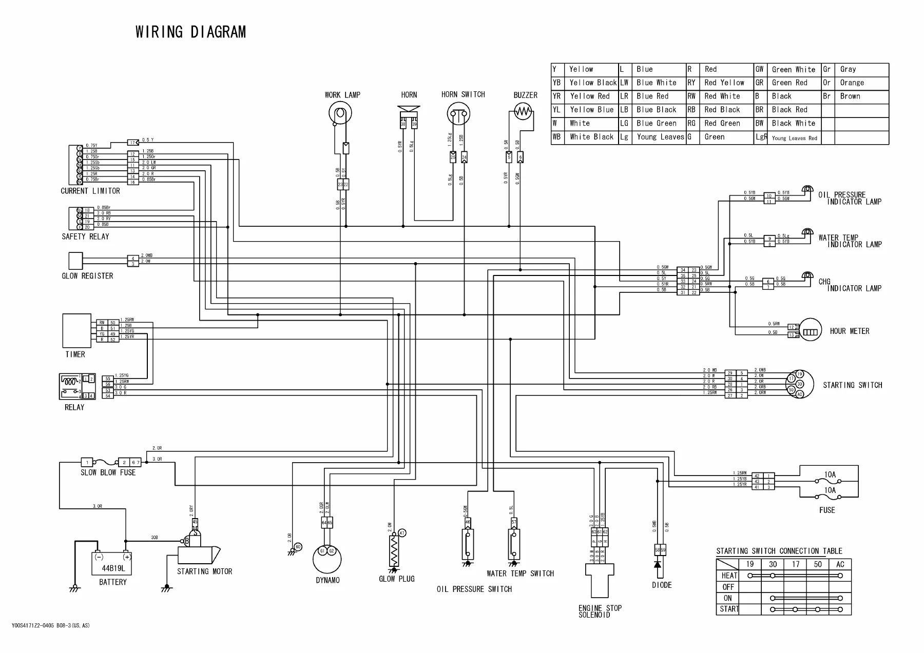
Figures 11 and 12 cover the electric parts in both wiring and equipment form, with a dedicated wiring diagram page showing the current limiter, safety relay, glow register, timer, relay, slow blow fuse, starting motor, dynamo, glow plug, oil pressure switch, water temp switch, engine stop solenoid, diode, work lamp, horn, horn switch, buzzer, oil pressure indicator lamp, water temp indicator lamp, charging indicator lamp, hour meter, starting switch and fuse. The colour code table lists yellow, black, blue, red, green, white, brown, grey and their combinations. Terminal numbers, wire gauges and connection points are printed exactly as Yanmar issued them.
Undercarriage, Track Frame & Crawler
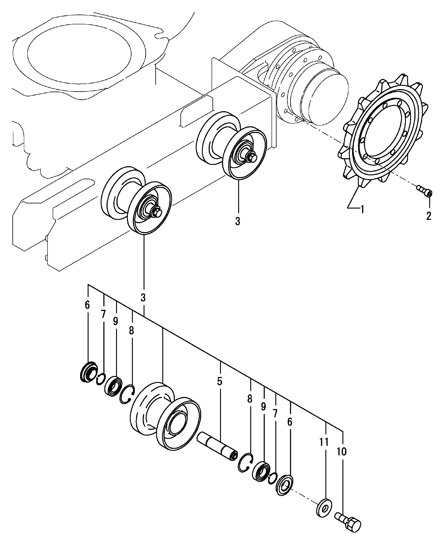
Figures 13, 14, 25, 26 and 38 address the sprocket, track roller, shaft, seal, circlip, ball bearing, side clutch washer, crawler rubber, idler, slider, adjust bolt, cover and the track frame, turning frame and travel motor. The sprocket section lists the 18-tooth sprocket, M10X25 bolts, track roller, roller shaft, seals, circlips, bearing 6005 and side clutch washer. The crawler, idler and adjust section covers the idler, shaft, seal, spring washer, circlip 30, circlip 62(H), ball bearing 6206, M12X25 plated bolts, side clutch washer, slider, adjust bolt, cover, M8X16 bolts, M20 nut and rubber crawler. The travel motor section lists the motor cmp, base plate assembly, ring, plug, springs, needle, ball bearing, O-rings, snap rings, gears, seal ring, thrust plate, seal, slant plate, ball, needle, thrust washer, pin, carrier kit, oil seal, cylinder barrel assembly, O-ring kit and shaft.
Operator Controls, Seat & Cab Structure
Figures 15 through 24, 27, 28, 29 and 30 cover the control equipment in every configuration: link stand, stopper lever, operate lever (standard pattern and JD pattern), travel and blade lever, swing pedal, PTO pedal and variable leg operate. The step and turning lock, seat and mount, bonnet and ROPS bar are also fully broken down. You will find the lever, boot, knob, joint, base, arm, spring, washer, thrust washer, ball link, rod, elbow, nut, cotter pin, bush and grease nipple for each control. The ROPS bar section lists the rollbar assembly top, bottom, bracket assembly, pivot pin, hex bolts, locking pin, vertical hinge pins, seat belt assembly, shims and the M12 washers and spring washers.
Hydraulic Pump, Cylinders & Motors
Figures 31 through 40 detail the hydraulic oil pump and joint, boom cylinder, arm cylinder, bucket cylinder, swing cylinder, blade cylinder, widen/shorten cylinder, travel motor, turning motor and swivel joint. The pump section lists the mount, parallel pin, bearing holder assembly, joint, coupling, spring pin, bolts, seal kit, steel ball, washer and O-rings. Each cylinder is exploded into head, tube, bush, rod, piston, U-nut, seal set, gasket, back-up ring, O-ring, grease nipple and cover. The swing cylinder section includes the seal set, head, gasket, rock washer, bush, nut, piston, tube, rod and rod assembly. The turning motor section lists the bearing retainer, pinion 13T, needle bearing, circlips, ball bearing, inner bearing, plug, motor cmp, roller, drive, end cap, spacer plate, housing, output shaft, thrust race, needle bearing, seal kit and flange.
Control Valve Assembly & Check Valve
Figures 41 through 47 cover the control valve in six sub-sections plus the check valve. The valve is broken down into P1 section, main relief valve, option section, swing section, boom section, bucket section, drive section, travel section, blade section, PTO section, arm section and turning section. Each section is further exploded into plugs, O-rings, back-up rings, plates, springs, seats, caps, check valves, overload valves and bolts. The check valve section lists the valve, O-ring, piston, check valve assembly and M8X80 bolts. This is the most detailed hydraulic control documentation in the catalog and is indispensable when resealing or replacing valve sections.
Hydraulic Piping, Hoses & Swivel Joint
Figures 49 through 56 and 40 cover the hydraulic oil piping from tank to pump to control valve, control valve to turning motor and swing cylinder, control valve to swivel, return piping, PTO piping at frame and boom ends, track frame piping and boom piping. The catalog lists every elbow, joint, connector, adapter, O-ring, hose, clamp, band, cover, support, collar and plate with the exact Yanmar part number. Hose codes such as P204BC078, P204BB056, G206BV080K, P202AB048, G604YY032, H604BY045 and P602YY043 are printed with quantities and positions so you can match the original routing.
Boom, Arm, Bucket Link, Bucket & Blade
Figures 57 through 61 cover greasing, the boom and boom bracket, arm and bucket link, bucket and blade. The boom section lists the boom (yellow), pin bush, cotter pin, shims, pins of various lengths, grease nipples, clips, bracket, bolts, spring washer, lock nut and shim 30 pin adjust. The arm section lists the arm 670 (yellow), bushes, pins, link, bucket link assembly, arm L and arm bucket. The bucket section lists the pin kit, cotter pins, shims, pins, grease nipples, bucket 350 (yellow), side teeth and teeth. The blade section lists the cotter pins, shims, pins, blade (green), blade L, blade R, M8X16 bolts, M10X20 bolts, lock nuts, washers, spring washers, grease nipples, plates, rubber, support, collar, cover, band and label. Every pin diameter, length and shim thickness is printed for accurate reassembly.
Why This Yanmar B08-3 Parts Catalog Matters
When you are repairing or rebuilding a Yanmar B08-3 crawler backhoe, the difference between the right part and a near-match is often a few millimetres, a different thread pitch or a revised seal design. This parts catalog gives you the genuine Yanmar part numbers for every assembly on the machine, from the smallest cotter pin and O-ring to the complete control valve, travel motor and boom cylinder. The exploded illustrations show exactly how each component fits together, and the interchangeability marks, change marks and level indicators tell you which parts supersede earlier designs. Whether you are servicing a US-spec B08-3 or an Australian-spec machine, the catalog covers both and lists the engine as the 2TNE68-EBVA with serial range 20007 and up. The label and safety decal section lets you restore the machine to its original specification, and the wiring diagram gives you the colour codes, terminal numbers and wire gauges needed to diagnose electrical faults. The hydraulic piping sections, with their full hose codes and routing, are particularly valuable when replacing damaged hoses or rebuilding a machine that has been partially disassembled.
IMAGES PREVIEW
Instant PDF Delivery — No Shipping, No Waiting
This Yanmar B08-3 parts catalog is delivered as an instant PDF download after payment. There is no physical book to ship, no courier to wait for and no import charges. You can open the file on any device — laptop, tablet or smartphone — and print the pages you need for the workshop. The PDF is formatted so you can zoom into the exploded diagrams and part tables, and the file is yours to keep. Whether you are a workshop technician, a parts counter specialist or an owner-operator maintaining your own B08-3, having the complete parts catalog at your fingertips means faster ordering, fewer returns and a machine that goes back to work sooner.
Reviews
There are no reviews yet.