Yanmar B110W Wheel Excavator Service Manual – PDF DOWNLOAD
YANMAR B110W WHEEL EXCAVATOR SERVICE MANUAL:
IMAGE PREVIEW:
Yanmar B110W Wheel Excavator Service ManualYanmar B110W Wheel Excavator Service Manual – PDF DOWNLOAD
DESCRIPTION:
Yanmar B110W Wheel Excavator Service Manual – PDF DOWNLOAD
The individual assemblies of the manufacturer machine program and the functions of and adjustments to the installed units are described in this service manual. The hydraulics and electrics diagrams and sectional representations combined with the operating instructions and spare parts list should make maintenance and repair work easier.
Descriptions of work procedures and assembly steps were consciously omitted, because big repairs are generally performed by qualified and experienced workshop personnel, who are masters at this routine work. Safety and cleanliness at the workstation is the highest priority when performing repairs.
Using tools in perfect condition and generally replacing sealing components during each repair should be a matter of course. Provided no special values are specified, screw connections are to be fastened with the usual tightening torques. This service manual has been issued by the customer service department with the aim of jointly improving the servicing of manufacturer machines.
The service messages we send out for information can serve as a supplement. We keep this manual up to date with continuous additions. This document may be copied and transmitted to third parties neither wholly nor in excerpts without our consent. The division of the main groups can be seen in the table of contents.
The accident prevention regulations of the responsible employer’s liability insurance association are to be strictly observed. Attentiveness when performing repairs is the best way of preventing accidents. We therefore recommend studying the relevant instructions concerning the intended repair in detail.
Maintenance and repair work on machines in the field may only begin once the work equipment has been placed on the ground, the engine is turned off, the machine is secured against rolling away, and the hydraulic system has been relieved of pressure. If repair work is performed by qualified personnel in the workshop, the relevant accident prevention regulations apply here too.
TABLE OF CONTENTS:
Yanmar B110W Wheel Excavator Service Manual – PDF DOWNLOAD
B110W - Cover 12/20/2018.......................................................................................... 1
List of Contents............................................................................................... 1
01 General..................................................................................................... 3
Foreword / User instructions............................................................................... 5
Safety and accident prevention............................................................................. 7
Description of safety signs................................................................................ 19
Tightening torques of pistons or piston nuts............................................................... 25
Tightening torques of guide bushings....................................................................... 26
Pictograms................................................................................................. 27
Measuring connections...................................................................................... 35
Units...................................................................................................... 37
02 Technical Data.............................................................................................. 47
Technical data............................................................................................. 49
Drift values............................................................................................... 59
03 Diesel Engine............................................................................................... 61
03.53.02 Operating manual TD / TCD 3.6 L4.................................................................. 63
Notes.................................................................................................. 64
Foreword............................................................................................... 65
Table of contents...................................................................................... 67
General................................................................................................ 68
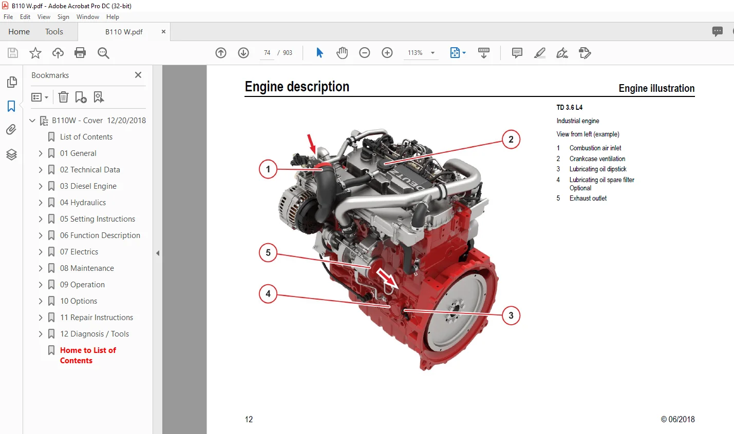
Engine description..................................................................................... 70
Model.............................................................................................. 70
Engine illustration................................................................................ 73
Lubricating oil plan............................................................................... 79
Fuel system plan................................................................................... 80
Coolant plan....................................................................................... 81
Exhaust gas recirculation.......................................................................... 82
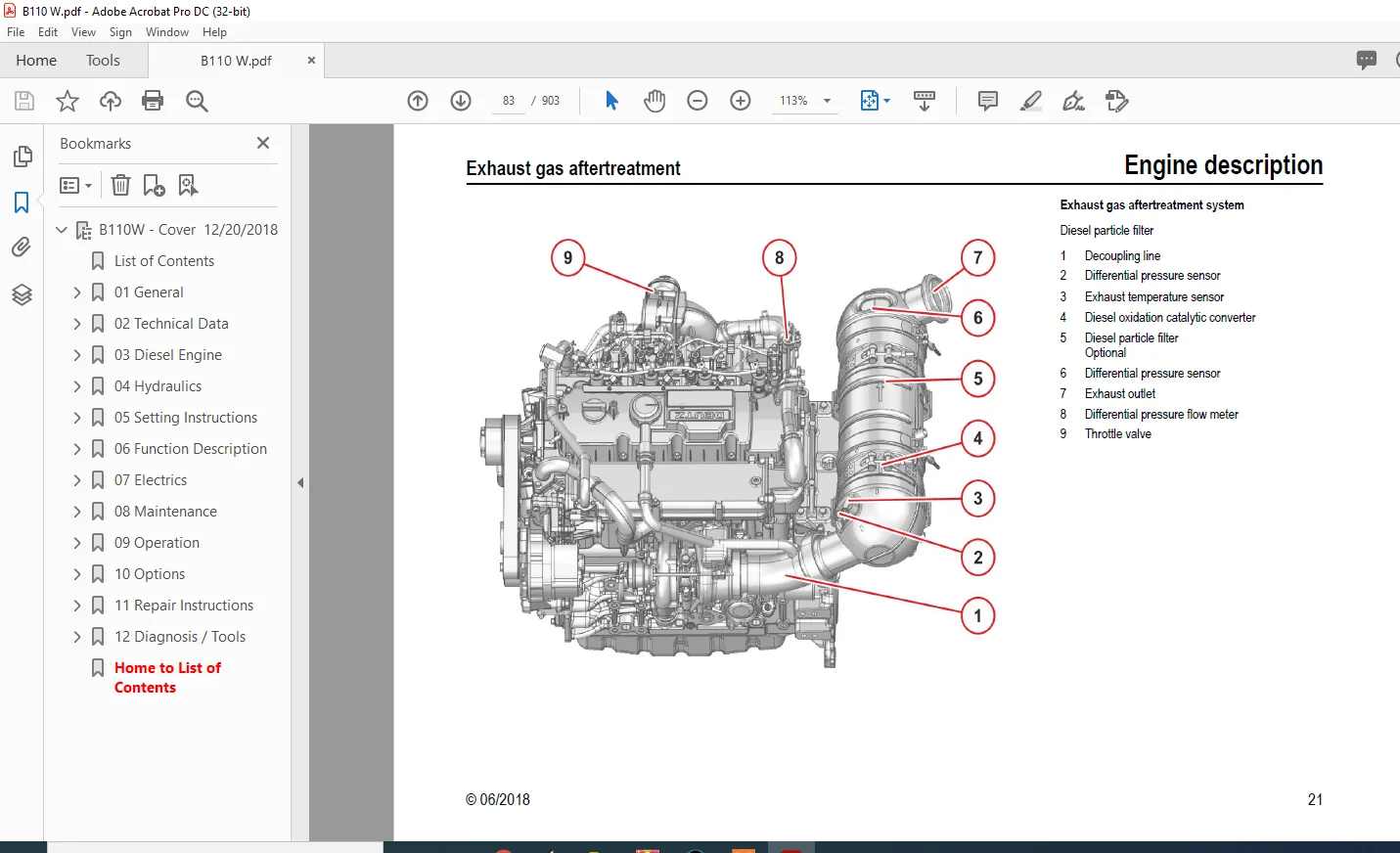
Exhaust gas aftertreatment......................................................................... 83
Electrics/Electronics.............................................................................. 85
Operation.............................................................................................. 87
Ambient conditions................................................................................. 87
Initial commissioning.............................................................................. 89
Start process...................................................................................... 92
Operation monitoring............................................................................... 93
Exhaust gas aftertreatment system.................................................................. 97
Passive regeneration...............................................................................102
Stopping process...................................................................................105
Operating media........................................................................................107
Lubricating oil....................................................................................107
Fuel...............................................................................................109
Coolant............................................................................................110
SCR reduction agent................................................................................112
Maintenance............................................................................................113
Maintenance schedule...............................................................................113
Service and maintenance work...........................................................................116
Lubricating oil system.............................................................................116
Fuel system........................................................................................118
SCR (Selective Catalytic Reduction)................................................................121
Cooling system.....................................................................................122
Suction system.....................................................................................124
Belt drives........................................................................................126
Engine cleaning....................................................................................128
Electrical system..................................................................................129
Faults.................................................................................................130
Fault table........................................................................................130
Engine management..................................................................................135
Transport and storage..................................................................................138
Transport..........................................................................................138
Engine corrosion protection........................................................................139
Technical data.........................................................................................142
Engine and setting data............................................................................142
Tools..............................................................................................144
03.53.12 Workshop Manual TD / TCD 3.6 L4...................................................................149
Table of contents......................................................................................151
1 Foreword.........................................................................................153
2 General..........................................................................................157
3 Safety information / User iformation.............................................................161
5 Job card overview................................................................................171
5.1 Sorted alphabetically..........................................................................171
5.2 Sorted numerically.............................................................................177
6 Job cards........................................................................................183
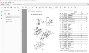
Renewing the crankshaft sealing ring {flywheel side)...................................................185
Removing and installing the gasket housing ............................................................189
Removing and installing the transfer line..............................................................193
Removing and installing the oil pressure regulating valve..............................................197
Closing parts..........................................................................................201
Oil measuring device...................................................................................203
Line...................................................................................................205
Removing and installing the lubricating oil pan........................................................207
Closing parts..........................................................................................215
Drain valve............................................................................................217
Oil filling............................................................................................219
Removing and installing the V-belt pulley / V-ribbed pulley............................................221
Removing and installing the flywheel (Fastening parts).................................................233
Removing and installing the sensor wheel...............................................................237
V-belt pulley..........................................................................................241
Checking the compression pressure (when injectors are removed).........................................243
Removing and installing the cylinder head cover........................................................251
Renewing the crankshaft sealing ring (opposite side to flywheel).......................................257
Cover..................................................................................................261
Removing and installing the control valve..............................................................263
Removing and installing the lubricating oil cooler.....................................................267
Installing the lubricating oil filter..................................................................271
Removing and installing the oil suction pipe...........................................................273
Removing and installing the lubricating oil line (exhaust turbocharger)................................277
Removing and installing the lubricating oil return line (exhaust turbocharger).........................281
Lubricating oil line...................................................................................287
Removing and installing the high-pressure pump.........................................................289
Removing and installing the injector...................................................................297
Fastening parts........................................................................................305
Fuel pre-filter........................................................................................307
Fuel filter............................................................................................309
Supply pump (Fuel).....................................................................................311
Removing and installing the rail.......................................................................313
Removing and installing the fuel line (injector, rail, high-pressure pump).............................323
Removing and install the charge air line...............................................................329
Intake nozzle (exhaust turbocharger)...................................................................333
Charge air manifold....................................................................................335
Removing and installing the coolant pump...............................................................337
Drive components.......................................................................................343
V-rib belt pulley......................................................................................345
Removing and installing the thermostat.................................................................347
Checking the thermostat (in the removed state).........................................................351
Line ..................................................................................................355
Line...................................................................................................357
Suction fan............................................................................................359
Pressure fan...........................................................................................361
Adapter................................................................................................363
Removing and installing the exhaust line...............................................................365
Removing and installing the flutter valve..............................................................369
Removing and installing the cooler.....................................................................373
Removing and installing the exhaust gas return valve...................................................377
Removing and installing the exhaust gas return pipe....................................................385
Removing and installing the Venturi tube...............................................................391
Removing and installing the temperature sensor.........................................................397
Removing and installing the pressure transmitter.......................................................401
Connection (Crankcase housing, exhaust gas circulation, coolant line)..................................407
Screw plug (Thermostat housing, exhaust gas circulation, coolant line).................................409
Holder.................................................................................................411
Holder.................................................................................................413
Holder.................................................................................................415
Compensator structure (Exhaust line)...................................................................417
Line (Crankcase housing, exhaust gas circulation, coolant line)........................................419
Line (Thermostat housing, exhaust gas circulation, coolant line).......................................421
Removing and installing the turbocharger...............................................................423
Removing and installing the belt tensioner (V-rib belt)................................................427
Removing and installing the console (V-rib belt, level 1)..............................................431
Removing and installing the Starter....................................................................435
Fastening parts........................................................................................439
Generator .............................................................................................441
Engine mounting .......................................................................................443
Engine mounting .......................................................................................445
Engine mounting .......................................................................................447
Engine mounting .......................................................................................449
Removing and installing the pressure/temperature sensor (charge air)...................................451
Fastening parts........................................................................................455
Fastening parts........................................................................................457
Fastening parts........................................................................................459
Fastening parts........................................................................................461
Relay..................................................................................................463
Removing and installing turning gear/ locking device...................................................465
Impulse transmitter (crankshaft).......................................................................469
Impulse transmitter (camshaft).........................................................................471
Installing the pressure sensor (oil pressure)..........................................................473
Removing and installing the connection housing.........................................................475
Connection housing.....................................................................................479
Removing and installing the glow plugs.................................................................481
Removing and installing the sensor (NOx)...............................................................485
Removing and installing pressure sensor (exhaust back pressure) SCR (Selective Catalytic Reduction)....489
Removing and installing the dosing device SCR {Selective Catalytic Reduction)..........................493
Removing and installing temperature transmitter (before diesel oxidation catalyst).....................497
Removing and installing the compensator (exhaust turbocharger).........................................501
Holder.................................................................................................505
Holder.................................................................................................507
Exhaust back pressure sensor (mixing pipe) SCR (Selective Catalytic Reduction).........................509
Temperature sensor (air intake temperature, ambient air temperature)...................................511
Coolant line SCR (Selective Catalytic Reduction).......................................................513
Catalytic converter DOC (Diesel Oxidation Catalist) / DPF (Diesel Particle Filter).....................515
Catalytic converter SCR (Selective Catalytic Reduction)...............................................517
Supply pump SCR (Selective Catalytic Reduction)........................................................519
Console................................................................................................521
Tank SCR (Selective Catalytic Reduction)...............................................................523
Mixing pipe (Screw connection).........................................................................525
Removing and installing the coolant compressor.........................................................527
Fastening parts........................................................................................533
Removing and installing hydraulic pump drive...........................................................535
8 Special tools........................................................................................539
Bleeding the fuel system ..................................................................................553
AdBlue – DEF Installation..................................................................................555
04 Hydraulics..................................................................................................563
0100 ► 0156 Articulated boom - standard....................................................................565
0157 ► XXXX Articulated boom - standard....................................................................566
0100 ► 0156 Articulated boom - with options................................................................567
0157 ► XXXX Articulated boom - with options................................................................568
0157 ► XXXX Articulated boom - with options; UNDERCARRIAGE ................................................569
0157 ►0451 Articulated boom - with options; UPPER CARRIAGE ................................................570
0157 ► XXXX Articulated boom - with options; CONTROL VALVE-1 SX14 .........................................571
0157 ► XXXX Articulated boom - with options; CONTROL VALVE-2 DPX100 .......................................572
0452 ► XXXX Articulated boom - with options; UPPER CARRIAGE................................................573
05 Setting Instructions........................................................................................575
General setting instructions...............................................................................577
Hydromatik tightening values...............................................................................579
Travel hydraulics..........................................................................................581
Control valve SX14.........................................................................................595
Control valve DPX100/6+1...................................................................................599
0104 ► 0156 Pilot control unit.............................................................................603
0157 ► XXXX Pilot control unit.............................................................................607
Working hydraulics.........................................................................................611
Work variable displacement pump............................................................................621
06 Function Description........................................................................................625
Pilot control device 4TH6..................................................................................627
Grip Options - Joystick....................................................................................629
07 Electrics...................................................................................................635
Cable colors...............................................................................................637
07.53.12 Vehicle electrics TW110 SCRT_0104-_V0.1.4
from SERIAL-NO.: TW11040104 to TW1104XXXX
............639
01 Cover sheet.........................................................................................639
1 | 6304040001.....................................................................................639
2 | 6304040002.....................................................................................640
3 | 6304040003.....................................................................................641
4 | 6304040004.....................................................................................642
5 | 6304040005.....................................................................................643
02 Schematic circuit diagram...........................................................................644
10 | 6304041010....................................................................................644
11 | 6304041011....................................................................................645
12 | 6304041012....................................................................................646
13 | 6304041013....................................................................................647
14 | 6304041014....................................................................................648
15 | 6304041015....................................................................................649
16 | 6304041016....................................................................................650
17 | 6304041017....................................................................................651
18 | 6304041018....................................................................................652
19 | 6304041019....................................................................................653
20 | 6304041020....................................................................................654
21 | 6304041021....................................................................................655
22 | 6304041022....................................................................................656
23 | 6304041023....................................................................................657
24 | 6304041024....................................................................................658
25 | 6304041025....................................................................................659
26 | 6304041026....................................................................................660
27 | 6304041027....................................................................................661
28 | 6304041028....................................................................................662
29 | 6304041029....................................................................................663
30 | 6304041030....................................................................................664
31 | 6304041031....................................................................................665
32 | 6304041032....................................................................................666
33 | 6304041033....................................................................................667
34 | 6304041034....................................................................................668
35 | 6304041035....................................................................................669
03 Cable harness.......................................................................................670
101 +1 | 6303542011................................................................................670
102 +1 | 6303542012................................................................................671
103 +1 | 6303542013................................................................................672
104 +2 | 6304043011................................................................................673
105 +2 | 6304043012................................................................................674
106 +2.1 | 6293106041..............................................................................675
107 +9 | 6293106042................................................................................676
108 +3 | 6293543030................................................................................677
109 +7 | 6303543020................................................................................678
110 +2.2 | 6303740011..............................................................................679
111 +2.3 | 6303740121..............................................................................680
112 +2.4 | 6293151041..............................................................................681
113 +6 | 6293043040................................................................................682
114 +8 | 6293240031................................................................................683
115 +1.1 | 6293042030..............................................................................684
116 +1.2 | 6293042040..............................................................................685
117 +1.3 | 5350555741..............................................................................686
118 +9 | 6304265010................................................................................687
120 +5 | 6303544010................................................................................688
121 +5 | 6303544020................................................................................689
122 +5 | 6293044050................................................................................690
123 +5 | 6293044060................................................................................691
124 +5 | 6303544070................................................................................692
126 +5 | 6303544030................................................................................693
04 overview............................................................................................694
201 | 6303540010...................................................................................694
202 | 6303542022...................................................................................695
203 | 6303542023...................................................................................696
204 | 6303540011...................................................................................697
205 | 6303540512...................................................................................698
206 | 6303540013...................................................................................699
207 +1 | 6303542021................................................................................700
208 +1 | 6303542024................................................................................701
Monitoring displays........................................................................................703
Heating und climate regulator..............................................................................711
Relay assignment...........................................................................................713
Fuse assignment............................................................................................717
Structural diagram, diesel engine control unit.............................................................723
Structural diagram, fan control unit.......................................................................725
Structural diagram, electrical components..................................................................727
Diagnostics and programming connection.....................................................................728
08 Maintenance.................................................................................................729
Specification for fuels, lubricants and coolants...........................................................731
Inspection plan............................................................................................735
Measurement protocol.......................................................................................739
09 Operation...................................................................................................743
Keypad operation...........................................................................................745
Instructions for using the combo-tool (display)............................................................747
10 Options.....................................................................................................781
Pressure setting, front dozer blade........................................................................783
Exhaust gas after-treatment system – Diesel particle filter (DPF) replacement.............................787
Auto-idling system ........................................................................................795
11 Repair Instructions.........................................................................................801
Fitting hydraulic screw connections........................................................................803
Adhesive kit – cab windows.................................................................................815
Tilting the cab............................................................................................817
12 Diagnosis / Tools...........................................................................................821
Special tools - purchased parts............................................................................823
ACTIA - Diagnostic Messaging Specification.................................................................831
SerDia 2010 - Diagnoses- and Error Codes SPN / FMI.........................................................853
Diagnostics and programming port - purchased parts.........................................................901
Home to List of Contents....................................................................................... 1
PLEASE NOTE:
This is the SAME exact manual used by your dealers to fix your vehicle.
The same can be yours in the next 2-3 mins as you will be directed to the download page immediately after paying for the manual.
Any queries / doubts regarding your purchase, please feel free to contact [email protected]
SK
✹
What Our Customers Say
★★★★★Live reviews from customers
Loading customer reviews...
🌟 Related Products
Discover more professional manuals for your equipment