Yanmar C12R (3WD) Excavator Service Manual – PDF Download
YANMAR C12R (3WD) EXCAVATOR SERVICE MANUAL – PDF DOWNLOAD:
IMAGE PREVIEW:
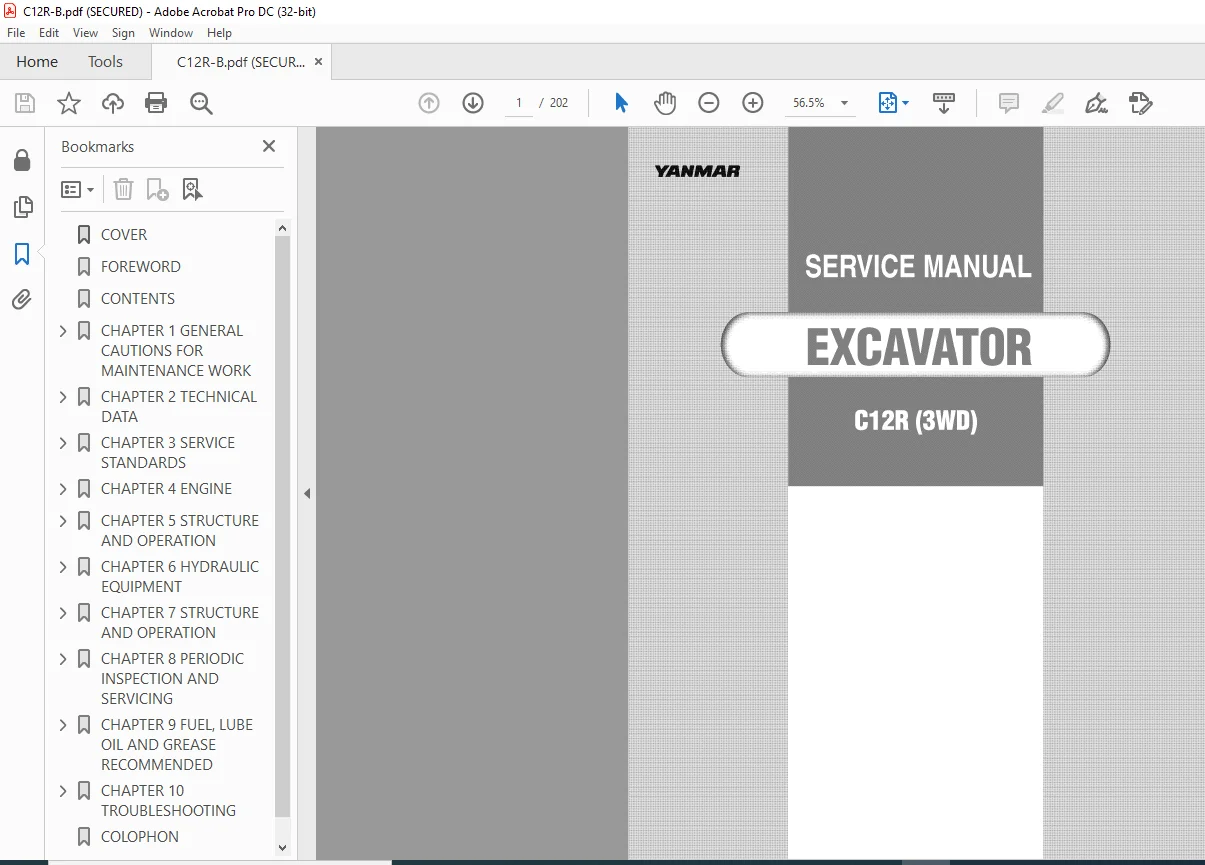
Yanmar C12R (3WD) Excavator Service ManualYanmar C12R (3WD) Excavator Service Manual
DESCRIPTION:
Yanmar C12R (3WD) Excavator Service Manual – PDF Download
Yanmar C12R (3WD) Excavator Service Manual – PDF Download
This service manual outlines procedures for servicing YANMAR construction machinery.
lt contains specifications, servicing instructions and handling cautions.
То oЬtain the maximum life and performance from YANMAR construction machinery, read this manual carefully and follow its instructions.
Please note that all dimensions and numerical values in this manual are for service reference, and are not inspection standards.
Descriptions and specifications in this manual are subject to change without notice due to design improvements, etc.Correct work means the quickest possiЫe completion of according to the correct procedures and the specified standards.
lt is important when conducting certain operations alway s to bear in mind the equipment, tools, gauges, materials, oil and grease, etc. that y ou must have ready, as well as items to Ье checked, adjusted, or disassemЫed, and cautions to watch out for. 1-2 Safety Precautions (1) Never attempt servicing while engine is running or immediately after stopping operation. (2) Wear work cloths, safety shoes and helmet. (3) Check the equipment and tools before use.
Especially, Ье sure to check the crane, lifting equipment and tools. (4) When working together with other persons, allocate everyone’s share of job, arrange the signals and act in concert with the other persons. (5) The operation of the crane and slinging work must Ье performed Ьу qualified persons. (6) Do not enter or pass under the raised load. (7) Lift and support the massive parts Ьу crane before removing the installation bolts.
(8) Disconnect саЫеs from battery before repairing the electric sy stem. (9) Remove the battery when welding the machine. 1-3 Preparations (1) Check the service record of the machine. (That is, check how many months or hours the machine has been used since the preceding overhaul, what was the trouЫe then and what parts were replaced.) (2) Have all servicing tools ready, i.e., tools, measuring devices (which have received periodic maintenance), containers, oil & grease, etc.
(3) Have the service literature (operation manual, parts catalog, etc.) ready. 1-4 Cautions for DisassemЫy and ReassemЫy (1) Clean the machine before disassemЫy.
(2) Check and record the condition of the machine before disassemЫy : • Model, machine number, operation hours • Reasons for repair, history of repair • Contamination of filters • Fuel and oil condition • Damage to parts, etc. (3) Place alignment marks оп the necessary parts to facilitate reassemЫy. (4) Clean all the removed parts and new replacement parts and put them in order. (5) Use new seals, split pins, etc. for reassemЫy.
TABLE OF CONTENTS:
Yanmar C12R (3WD) Excavator Service Manual – PDF Download
COVER................................................................................. 1
FOREWORD.............................................................................. 2
CONTENTS.............................................................................. 3
CHAPTER 1 GENERAL CAUTIONS FOR MAINTENANCE WORK....................................... 6
1. General Cautions for Maintenance Work.......................................... 7
1-1 Correct Work.............................................................. 7
1-2 Safety Precautions........................................................ 7
1-3 Preparations.............................................................. 7
1-4 Cautions for Disassembly and Reassembly................................... 7
1-5 Cautions for Removal and Installation of Hydraulic Equipment.............. 8
1-6 Cautions for Removal and Installation of Hydraulic Piping................. 8
1-7 Cautions for Handling Seals............................................... 9
1-8 Correct Installation of Hydraulic Hose.................................... 9
1-9 Specifications of Hydraulic Hose.......................................... 12
1-10 Air Release Procedure for H.S.T. System.................................. 17
CHAPTER 2 TECHNICAL DATA.............................................................. 18
2. Technical Data................................................................. 19
2-1 Specifications............................................................ 19
2-2 Machine Dimensions........................................................ 24
2-3 Hydraulic Circuit Schematic............................................... 25
2-4 Wiring Diagram............................................................ 26
2-5 Weight of Components...................................................... 27
CHAPTER 3 SERVICE STANDARDS........................................................... 28
3. Service Standards.............................................................. 29
3-1 Machine Performance....................................................... 29
3-2 Engine.................................................................... 31
3-3 Undercarriage............................................................. 35
3-4 Control Devices........................................................... 36
3-5 Hydraulic Cylinder........................................................ 38
3-6 Work Implement............................................................ 39
3-7 List of Tightening Torque................................................. 40
3-7-1 Machine............................................................. 40
CHAPTER 4 ENGINE...................................................................... 42
4. Engine......................................................................... 43
4-1 Measurement, Inspection and Adjustment.................................... 43
4-1-1 Measuring the Compression Pressure.................................. 43
4-1-2 Adjusting the Valve Clearance....................................... 44
4-1-3 Checking the V-belt Tension......................................... 45
4-1-4 Checking the Fuel Injection Valve................................... 45
4-1-5 Checking and Adjusting the Fuel Injection Timing.................... 48
4-1-6 Adjusting the Maximum (or Minimum) Idling Speed..................... 51
4-1-7 Checking the Cooling Water System and Radiator for Water Leakage.... 51
4-1-8 Checking the Sensors................................................ 52
4-2 Measurement Procedure, Service Data and Corrective Action................. 53
4-2-1 Cylinder Head....................................................... 53
4-2-2 Cylinder Block...................................................... 58
4-2-3 Valve Rocker Arm.................................................... 60
4-2-4 Piston and Piston Rings............................................. 62
4-2-5 Connecting Rod...................................................... 65
4-2-6 Cam Shaft........................................................... 68
4-2-7 Crank Shaft......................................................... 69
4-2-8 Gears............................................................... 72
4-2-9 Trochoid Pump....................................................... 73
4-3 Precautions for Reassembly................................................ 75
4-4 Fuel Injection System..................................................... 78
4-4-1 Fuel Injection Pump................................................. 78
4-4-2 Fuel Injection Valve................................................ 78
4-4-3 Governor Mechanism.................................................. 79
4-4-4 Specifications of Fuel Injection Pump............................... 82
4-5 Electrical Equipment...................................................... 83
4-5-1 Starter Motor....................................................... 83
4-5-2 Alternator.......................................................... 84
4-5-3 Glow Plug........................................................... 86
CHAPTER 5 STRUCTURE AND OPERATION..................................................... 87
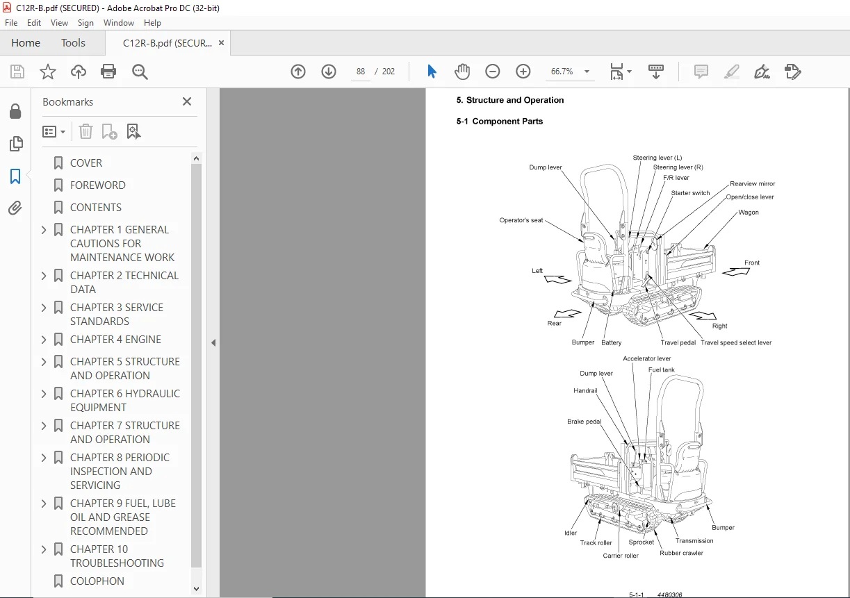
5. Structure and Operation........................................................ 88
5-1 Component Parts........................................................... 88
5-2 Mechanical Diagram of Power Transmission.................................. 89
5-3 Power Transmission........................................................ 90
5-3-1 Outline of H.S.T.................................................... 90
5-3-2 Features of H.S.T................................................... 90
5-4 Pulley and Velt........................................................... 92
5-5 Transmission Case......................................................... 93
5-5-1 Transmission Shaft and Gear......................................... 94
5-5-2 Side Clutch Hoke and Steering Brake................................. 95
5-6 Track Frame............................................................... 96
5-7 Idler and Track Roller.................................................... 97
5-7-1 Idler, Track Roller and Carrier Roller.............................. 97
5-8 Hydraulic Equipment Layout................................................ 98
CHAPTER 6 HYDRAULIC EQUIPMENT......................................................... 99
6. Hydraulic Equipment............................................................100
6-1 Outline...................................................................100
6-2 H.S.T.....................................................................101
6-3 Control Valve.............................................................128
6-4 Pressure Measurement Procedure............................................131
6-4-1 H.S.T...............................................................131
6-4-2 Control Valve.......................................................132
CHAPTER 7 STRUCTURE AND OPERATION.....................................................133
7. Structure and Operation........................................................134
7-1 Electrical Equipment of Machine...........................................134
7-1-1 Parts Layout of Electrical Equipment................................134
7-1-2 Monitor and Alarm Systems...........................................135
7-1-3 Wiring Diagram......................................................138
7-1-4 Circuit Description of Engine Start and Stop........................139
7-1-5 Circuit Description of Battery Charging.............................140
7-2 Undercarriage.............................................................141
7-2-1 Remove and Installation of Rubber Crawler...........................141
7-2-2 Inspection and Adjustment of Rubber Crawler.........................142
7-2-3 Disassembly and Reassembly of Idler.................................143
7-2-4 Disassembly and Reassembly of Track Roller (Carrier Roller).........144
7-3 Control Equipment.........................................................145
7-3-1 Structure and Comportment Parts.....................................145
7-3-2 Inspection and Adjustment of Travel Pedal...........................153
7-3-3 Checking and Adjusting the Brake Pedal..............................156
7-3-4 Inspection and Adjustment of Parking Brake..........................157
7-3-5 Inspection and Adjustment of F/R Lever..............................158
7-3-6 Inspection and Adjustment of Accelerator Lever......................159
7-3-7 Adjustment Procedure for Travel Speed Select Lever..................160
7-4 Power Transmission........................................................161
7-4-1 Removal and Reinstallation of Engine................................161
7-4-2 Transmission........................................................165
7-4-3 Replacement of Drive Belt...........................................174
7-5 Hydraulic Equipment.......................................................175
7-5-1 Hydraulic Cylinder..................................................175
7-5-2 Hydraulic Oil Tank..................................................177
7-5-3 Hydraulic Piping....................................................179
7-6 Wagon.....................................................................181
CHAPTER 8 PERIODIC INSPECTION AND SERVICING...........................................185
8. Periodic Inspection and Servicing..............................................186
8-1 List of Periodic Inspection and Servicing.................................186
CHAPTER 9 FUEL, LUBE OIL AND GREASE RECOMMENDED.......................................188
9. Fuel, Lube Oil and Grease Recommended..........................................189
CHAPTER 10 TROUBLESHOOTING............................................................190
10. Troubleshooting...............................................................191
10-1 Troubleshooting..........................................................191
10-1-1 Machine and Engine.................................................191
10-1-2 H.S.T..............................................................199
COLOPHON..............................................................................202
PLEASE NOTE:
This is the SAME exact manual used by your dealers to fix your vehicle.
The same can be yours in the next 2-3 mins as you will be directed to the download page immediately after paying for the manual.
Any queries / doubts regarding your purchase, please feel free to contact [email protected]
SK
✹
What Our Customers Say
★★★★★Live reviews from customers
Loading customer reviews...
🌟 Related Products
Discover more professional manuals for your equipment


 Excavator Service Manual")
 Excavator Service Manual")

 Excavator Service Manual")
 Excavator Service Manual")