Yanmar Lghting Tower LB446HB 1 H 1 LIGHT BOY Service Manual – PDF DOWNLOAD
YANMAR LGHTING TOWER LB446HB-1 H-1 LIGHT BOY SERVICE MANUAL:
IMAGE PREVIEW:
Yanmar Lghting Tower LB446HB 1 H 1 LIGHT BOY Service ManualYanmar Lghting Tower LB446HB 1 H 1 LIGHT BOY Service Manual
DESCRIPTION:
Yanmar Lghting Tower LB446HB 1 H 1 LIGHT BOY Service Manual – PDF DOWNLOAD
This service manual is intended for service engineers who maintain the YANMAR construction machinery, and describes the specifications, maintenance procedures of individual machine sections, and operational precautions.
Read this manual carefully and become familiar with your YANMAR machinery so that you will be able to quickly and accurately maintain and keep it in perfect working order throughout its life.
The dimensions and other values referred to in this manual are for your reference in servicing, and should not be considered as the values stipulated in the Inspection Standard.
This manual represents the most up-to-date information at the time of publication and is subject to change without notice to reflect specification changes for performance improvement or technological advancement, and/or correction of typographical errors.
If you find any discrepancies between your machine and the information in this manual, obtain the most up-to-date information from our Customer Service Group.
You will be informed of major improvements and specification changes by delivery of the revised version of this manual.
TABLE OF CONTENTS:
Yanmar Lghting Tower LB446HB 1 H 1 LIGHT BOY Service Manual – PDF DOWNLOAD
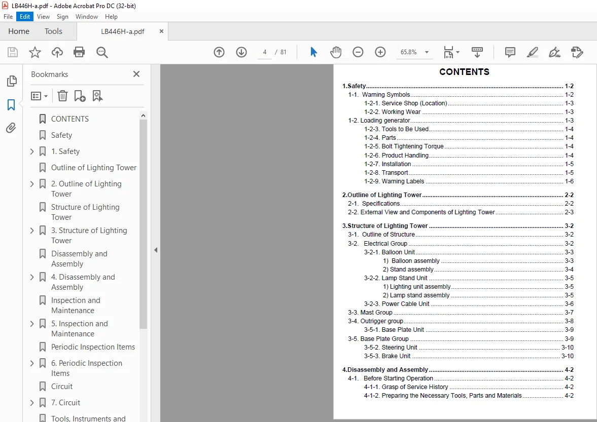
CONTENTS................................................................................................................................................................................................................................................................ 4
Safety.................................................................................................................................................................................................................................................................. 7
1. Safety............................................................................................................................................................................................................................................................... 8
1-1. Warning Symbols................................................................................................................................................................................................................................................ 8
1-2. Loading generator.............................................................................................................................................................................................................................................. 9
Outline of Lighting Tower...............................................................................................................................................................................................................................................13
2. Outline of Lighting Tower............................................................................................................................................................................................................................................14
2-1. Specifications.................................................................................................................................................................................................................................................14
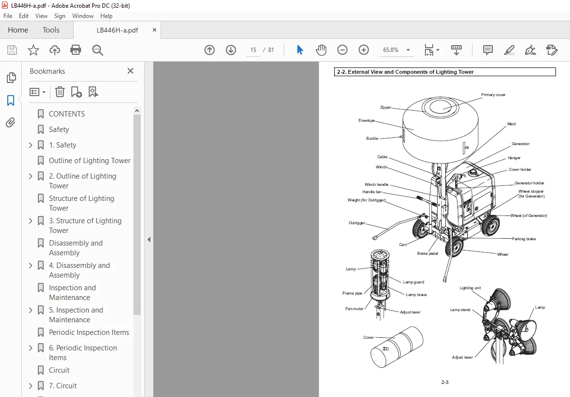
2-2. External View and Components of Lighting Tower.................................................................................................................................................................................................................15
Structure of Lighting Tower.............................................................................................................................................................................................................................................17
3. Structure of Lighting Tower..........................................................................................................................................................................................................................................18
3-1. Outline of Structure...........................................................................................................................................................................................................................................18
3-2. Electrical Group...............................................................................................................................................................................................................................................18
3-3. Mast Group.....................................................................................................................................................................................................................................................23
3-4. Outrigger group................................................................................................................................................................................................................................................24
3-5. Base Plate Group...............................................................................................................................................................................................................................................25
Disassembly and Assembly................................................................................................................................................................................................................................................27
4. Disassembly and Assembly.............................................................................................................................................................................................................................................28
4-1. Before Starting Operation......................................................................................................................................................................................................................................28
4-2. Disassembly and Assembly Procedures............................................................................................................................................................................................................................28
1. Loosen the set screw (M10X20) in the flange of the balloon assembly..........................................................................................................................................................................................32
2. Lift off the balloon assembly from the stand assembly........................................................................................................................................................................................................32
1. Remove the receptacle housing of the lighting unit assemblies from the lamp stand assembly...................................................................................................................................................................33
2. Loosen the nuts (M16) and remove each lighting unit assembly with the washer, spring and two spacers from the shaft of the lamp stand unit...................................................................................................................33
1. Insert the contact remover 1 into the receptacle (plug) housing 2 from the opposite side. Be careful of direction of the tip of the contact remover..........................................................................................................34
2. Push the contact remover to release housing lance 3 in the receptacle (plug) housing.........................................................................................................................................................................34
3. Pull the cable to remove the pin (socket) contact 4..........................................................................................................................................................................................................34
1. Loosen the button screw (M8X10) in the shaft of the stand assembly...........................................................................................................................................................................................35
2. Lift off the stand assembly from the forth mast..............................................................................................................................................................................................................35
3. Remove the washer and the spacer (stand) from the fourth mast................................................................................................................................................................................................35
1. Loosen the adjust lever......................................................................................................................................................................................................................................35
2. Lift off the lamp stand unit from the fourth mast............................................................................................................................................................................................................35
1. Loosen the bolt (M12X40) for the hanger......................................................................................................................................................................................................................36
2. Remove the eyebolt with the grommet from the shackle by loosing it...........................................................................................................................................................................................36
3. Apply the parking brake to prevent the cart from moving. Loosen the bolt & washers (M12X25), and then remove the stoppers (generator) from both sides of the front of the base plate unit....................................................................36
4. Lift up the front side of the generator (the side of the exhaust outlet.) to remove handle bar of the generator from the generator holder on the mast unit. Then pull back the generator and unload it from the base plate unit..............................36
1. Loosen six bolt & washers (M10X25)...........................................................................................................................................................................................................................37
2. Lift off the mast unit from the base plate...................................................................................................................................................................................................................37
1. Loosen three bolt & washers each (M10X25)....................................................................................................................................................................................................................37
2. Remove the right and left outriggers from the base plate unit................................................................................................................................................................................................37
1. Remove the envelope 1 from the balloon assembly by opening the zipper at the both side of the balloon assembly...............................................................................................................................................38
2. Loosen three screw & washers (M4X12) 2, and then remove the plate (air) 3 and the filter Ø200 4 from the flange 5............................................................................................................................................38
3. Loosen four button screw & washers (M8X25) 6, and then remove the primary cover 7, plate (cap) 8, seal (packing) 9, sheet (top) 10, seal (normal) 11 and the plate (top) 12..................................................................................38
4. Loosen the screw & washer (M4X8) 13, and then remove the joint blocks 2 14 from each frame pipe 15...........................................................................................................................................................38
5. Disconnect four cables of two sockets (E40) 16 from four curl codes 17 coming from the top of the frame pipes 15.............................................................................................................................................38
6. Loosen two screws (M4X35) 18, and then remove the stoppers 2 19 from each stopper 1 20 on the upper and lower plates 21,22...................................................................................................................................38
7. Pull out upper plate 21 from the frame pipes 15..............................................................................................................................................................................................................38
8. Disconnect four cables of two sockets (E40) 23 from the cable 1 (balloon) 24, and then pull out lower plate 22 from the frame pipes 15.......................................................................................................................38
9. Loosen two screw & washers (M4X16) 25, and then remove the stoppers 1 20 from the upper and lower plates 21,22...............................................................................................................................................38
10. Remove the lamps 26 from each socket (E40) 16,23 by loosening them..........................................................................................................................................................................................38
11. Loosen three screw & washers (M4X12) 27, and then remove two lamp guards 28 and lamp holders 29 each from the upper and lower plates 21,22..................................................................................................................38
12. Loosen two screw & washers (M4X20) 30, and then remove two sockets (E40) 23 each from the upper and lower plates 21,22......................................................................................................................................38
13. Loosen three screw & washers (M4X12) 31, and then remove the motor cover 1 32 from the motor cover 2 33.....................................................................................................................................................38
14. Loosen the screw & washer (M4X50) 34, and then remove the fan motor 35 from the flange 5....................................................................................................................................................................38
15. Disconnect the cable (joint) 1 36 and the cable (joint) 2 37 from the cable 1 (balloon) 24, buzzer 38 and the micro switch 39...............................................................................................................................38
16. Disconnect four curl codes 17 from the cable 1 (balloon) 24.................................................................................................................................................................................................38
17. Cut the wire bands at each top of four curl codes 17, and then pull out them from each frame pipe 15 through the joint block 1 40...........................................................................................................................38
18. Loosen the screw and washer (M4X8) 41, and then remove frame pipes 15 from each joint block 1 40............................................................................................................................................................39
19. Loosen four screw & washers (M4X8) 42, and then remove the bracket (contactor) 43 from the plate (bottom) 44................................................................................................................................................39
20. Pull out the cable 1 (balloon) 24 and remove the free bush 45 from the plate (bottom) 44....................................................................................................................................................................39
21. Loosen three button screws (M10X35) 46, and then remove the plate (bottom) 44, seal (packing) 47, sheet (bottom) 48 and the seal (normal) 49 from the flange 5..............................................................................................39
22. Pull out four joint block 1 40 from the motor cover 2 33, and then remove four washers (34DX21dX3.0t) 50, spacers (motor side) 51 and the vessel 52.........................................................................................................39
23. Loosen two screws (M3X6) 53, and then remove the buzzer 38 from the motor cover 2 33........................................................................................................................................................................39
24. Loosen two screw (M4X30) 54, and then remove the micro switch 39 and the micro switch cover 55 from the motor cover 2 33....................................................................................................................................39
1. Remove the grip shaft 1 from the stand 2 by loosening it.....................................................................................................................................................................................................40
2. Loosen two button screw & washers (M8X25) 3, and then remove covers (spring) 4 from the both side of the stand 2.............................................................................................................................................40
3. Remove the right and left spring (stand) 5,6 from the stand 2................................................................................................................................................................................................40
4. Remove the shaft (stand) 7 from the stand 2..................................................................................................................................................................................................................40
1. Disconnect two pin contacts 1 from the receptacle housing 2 by using a special tool..........................................................................................................................................................................40
2. Release three latches 3 of the mirror 4 and remove the light source tube 5 from the mirror 4.................................................................................................................................................................40
3. Turn the lamp 6 counterclockwise to remove it from the light source tube 5...................................................................................................................................................................................40
4. Disassemble other three lighting unit assemblies in the same order of this procedure 1 to 3..................................................................................................................................................................40
1. Remove the right and left springs (lamp stand) 1, 2 and spring (lever) 3 from the lamp stand 4...............................................................................................................................................................41
2. Remove the adjust lever 5 from the lamp stand 4 by loosing it................................................................................................................................................................................................41
3. Loosen the bolt (M8X20) 6....................................................................................................................................................................................................................................41
4. Remove two caps 7 from both side of the lamp stand 4.........................................................................................................................................................................................................41
1. Remove eight socket contacts 1 from the plug housing 2 with the tube 3 by using a special tool, contact remover..............................................................................................................................................41
2. Remove the tube 3 from the lamp cable 4......................................................................................................................................................................................................................41
3. Remove receptacle housing 5 from the mast unit...............................................................................................................................................................................................................41
4. Remove eight pin contacts 6 from the receptacle housing 5 by using the contact remover.......................................................................................................................................................................41
5. Remove the earth cable 7 from the receptacle housing 5 by using the contact remover..........................................................................................................................................................................41
6. Cut the wire bands at the mast group, and then remove the lamp cable 4.......................................................................................................................................................................................41
1. Loosen four screw & washers 1 and then remove the winch cover 2..............................................................................................................................................................................................42
2. Disconnect the tip of the wire 3 from the winch 4............................................................................................................................................................................................................42
3. Loosen three bolt & washers (M10X25) 5 and then remove the winch 4 from the first mast 6.....................................................................................................................................................................42
4. Loosen the bolt (M12X40) 7, and then remove the hanger 8 from the first mast 6...............................................................................................................................................................................42
5. Pull out the second mast 9 together with the third mast 10 from the first mast 6 pulling wire 11 to release the safety stopper of the pulley (second mast) 12................................................................................................42
6. Disconnecting the wire 11 from the third mast 10 by pulling it...............................................................................................................................................................................................42
7. Loosen six screws 13, and then remove the bracket (pulley) 14 from the second mast 9.........................................................................................................................................................................42
8. Pass a length of rope through the pulley 15 as shown in Fig. 4.2.17-2, and then pull out the third mast 10 from the second mast 9 pulling the rope to release safety stopper of the pulley (third mast) 15...................................................42
1. Remove the rubbers 1.........................................................................................................................................................................................................................................43
2. Loosen the bolts (M16 x 90) 2, and then remove the outrigger R 3 with spacers (out,r) 4 from the bracket (out,r)R 5..........................................................................................................................................43
3. Loosen the selflock nuts (M10) 6 and remove the weights (out,r) R 7 with the spacers 8 from the bracket (out,r) R 5..........................................................................................................................................43
4. Disassemble the left outrigger in the same order of this procedure 1 to 3....................................................................................................................................................................................43
1. Remove the snap rings 1 from the shaft of the base plate 2 and the front shaft of the steering unit 3........................................................................................................................................................44
2. Remove the front tire assembly 4 and the rear tire assembly 5 from the shaft of the base plate 2 and the front shaft of the steering unit 3..................................................................................................................44
3. Remove the snap rings 6 from the shafts......................................................................................................................................................................................................................44
4. Remove the tire assemblies on the other side in the same order of this procedure 1 to 3......................................................................................................................................................................44
5. Loosen four bolt & washers (M8x15) 7 and remove two side guards 8 from the base plate 16.....................................................................................................................................................................44
6. Loosen four bolt & washers (M10x25) 9 and remove the catchers 10 from the base plate 16......................................................................................................................................................................44
7. Loosen four bolt & washers (M12x25) 11 and remove the rail (R) 12 and the rail (L) 13 from the base plate 16.................................................................................................................................................44
8. Loosen two bolts (M6x15) 14 and remove the rails(E/G oil)CP 15 from the rail R 12............................................................................................................................................................................44
1. Loosen the bolt & washer (M12X25) 1 from the handle 2, and then remove the handle 2 from the base plate unit 3 and the link (handle) 4.......................................................................................................................45
2. Remove two sleeve bearings 5 from the base plate unit 3......................................................................................................................................................................................................45
3. Remove the snap ring 6 and the right and left handle grips 7 from the handle 2...............................................................................................................................................................................45
4. Loosen the selflock nut (M8) 8 and then remove the link (handle) 4 from the link (steering) 9................................................................................................................................................................45
5. Remove the push nut 10 and then remove the link (steering) 9 from the front shaft (L) 11.....................................................................................................................................................................45
6. Remove the push nuts 12, and then remove the link (front shaft) 13 from the front shaft(R) 14 and the front shaft(L) 11......................................................................................................................................45
7. Remove the front shaft (R) 14 and the front shaft (L) 11 from the base plate unit 3 by loosening them........................................................................................................................................................45
1. Loosen the nuts (M8) 1 and remove the bolt (M8X30) 2 from the brake pedal 3 and the brake shaft 4............................................................................................................................................................46
2. Remove the spring (brake) 5 from the base plate unit 6 and the brake shaft 3.................................................................................................................................................................................46
3. Loosen the through bolts (M12X75) 7 and 8, and then remove the right and left brakes 9 from the brake shaft 3................................................................................................................................................46
4. Remove the left and right sleeve bearings 10 from the base plate unit 6......................................................................................................................................................................................46
5. Remove the brake shaft 3 from the base plate 6...............................................................................................................................................................................................................46
Inspection and Maintenance..............................................................................................................................................................................................................................................47
5. Inspection and Maintenance...........................................................................................................................................................................................................................................48
5-1. Electrical Group...............................................................................................................................................................................................................................................48
1. Lay down the balloon flatly with the adjust lever............................................................................................................................................................................................................48
2. Open the zipper at the bottom of the balloon and roll up the envelope of the balloon.........................................................................................................................................................................48
3. Loosen each cramp of four frame pipes........................................................................................................................................................................................................................48
4. Extend the frame about 12 in. (30cm) long, and tighten cramps................................................................................................................................................................................................48
5. Expand the head of the lamp guard, then turn the lamp counterclockwise to remove the lamp....................................................................................................................................................................49
6. Screw a new lamp into the socket, then close the head of the lamp guard......................................................................................................................................................................................49
7. Loosen each cramp of four frame pipes and shorten the frame completely.......................................................................................................................................................................................49
8. Tighten the cramps...........................................................................................................................................................................................................................................49
9. Put the envelope over the frame, and zip it up...............................................................................................................................................................................................................49
1. Lay down the balloon flatly with the adjust lever............................................................................................................................................................................................................49
2. Open the zipper at the both sides of the balloon.............................................................................................................................................................................................................49
3. Remove the envelope of the balloon from the frame............................................................................................................................................................................................................49
4. Put a new envelope on the frame so that the grommet side of the envelope should come downward................................................................................................................................................................49
5. Zip up the both side of the balloon..........................................................................................................................................................................................................................49
1. Turn the lamp clockwise to install it into the light source tube.............................................................................................................................................................................................50
2. Fit the reflex mirror and the light source tube together.....................................................................................................................................................................................................50
3. Fix all three latches in order to stabilize the mirror to the light source tube..............................................................................................................................................................................50
1. Disconnect the couplers on the mast group and on the balloon assembly for the balloon type (LB446HB-1) or on the lamp stand assembly for the spotlight type (LB446H-1). Refer to section "4-2-3. Disconnection of Couplers" for removal of the couplers......53
2. Start the engine and confirm the speed is 3700 to 3750 rpm...................................................................................................................................................................................................53
3. Turn on lamp switches of the generator.......................................................................................................................................................................................................................53
4. Confirm locations of measuring points and measure each voltage. Locations of measuring points in the each plug housing and corresponding lamps and fan motor to those points are shown in Table 5.1.4........................................................53
1. Disconnect the couplers on the mast group and on the balloon assembly for the balloon type (LB446HB-1) or on the lamp stand assembly for the spotlight type (LB446H-1). Refer to Section "4- 2-3. Disconnection of Couplers" for removal of the couplers.....54
2. Cut the wire bands at the mast unit, and then remove the lamp cable..........................................................................................................................................................................................54
3. Set the mark on new lamp cable to the right hole of each mast as shown in Fig.5.1.4-5 and install the lamp cable to the first, second and third mast with two wire bands T50RSF each.........................................................................54
4. Bind the lamp cable and the first mast with the wire band SKB-2M.............................................................................................................................................................................................54
5. Cut off extra part of the wire bands.........................................................................................................................................................................................................................54
5-2. Mast Group.....................................................................................................................................................................................................................................................55
1. Remove wire from the pipe 1 at the lower part of the third mast..............................................................................................................................................................................................57
2. Pass a new wire 2 through the pipe 1 from above..............................................................................................................................................................................................................57
3. Pass the wire around pulley 3 on the bottom of the third mast from back to front.............................................................................................................................................................................57
4. Pass the wire around pulley 4 on the top of the second mast from front to back...............................................................................................................................................................................57
5. Pass the wire around pulley 5 on the bottom of the second mast from back to front............................................................................................................................................................................57
5-3. Outrigger Group................................................................................................................................................................................................................................................58
5-4. Base Plate Group...............................................................................................................................................................................................................................................58
5-5. Grounding......................................................................................................................................................................................................................................................59
Periodic Inspection Items...............................................................................................................................................................................................................................................61
6. Periodic Inspection Items............................................................................................................................................................................................................................................62
6-1. Inspection Items and Intervals.................................................................................................................................................................................................................................62
Circuit.................................................................................................................................................................................................................................................................65
7. Circuit..............................................................................................................................................................................................................................................................66
7-1. Electrical Circuit.............................................................................................................................................................................................................................................66
Tools, Instruments and Other Materials for Inspection and Maintenance...................................................................................................................................................................................................69
8. Tools, Instruments and Other Materials for Inspection and Maintenance................................................................................................................................................................................................70
8-1. Machines, Tools and Instruments................................................................................................................................................................................................................................70
Bolts and Nuts Tightening Torques.......................................................................................................................................................................................................................................73
9. Bolts and Nuts Tightening Torques....................................................................................................................................................................................................................................74
9-1. General Instructions...........................................................................................................................................................................................................................................74
9-2. Major Bolts and Nuts...........................................................................................................................................................................................................................................75
Troubleshooting.........................................................................................................................................................................................................................................................77
10. Troubleshooting.....................................................................................................................................................................................................................................................78
10-1. Troubleshooting Procedures....................................................................................................................................................................................................................................78
PLEASE NOTE:
This is the SAME MANUAL used by the dealerships to diagnose your vehicle
No waiting for couriers / posts as this is a PDF manual and you can download it within 2 minutes time once you make the payment.
Your payment is all safe and the delivery of the manual is INSTANT – You will be taken to the DOWNLOAD PAGE.
So have no hesitations whatsoever and write to us about any queries you may have : heydownloadss @gmail.com
SK
✹
What Our Customers Say
★★★★★Live reviews from customers
Loading customer reviews...
🌟 Related Products
Discover more professional manuals for your equipment